M. Boubakri | S. Chakroune* | S. Belhamdi
OPEN ACCESS
Recently, the induction motor comprises the majority of all motors utilized in machinery, and the operating efficiencies of these machines greatly impact the overall energy consumption in industry. Current motors are produced with higher efficiency ratings than standard motors, but the decision to replace an existing motor focuses on the actual cost savings that depend on several key points such as operating efficiency, percentage of time at given loads. Owing to the importance of induction motors, this work investigates vector control of a high efficiency induction motor (HEM). Most papers related to control concentrate on flux oriented for solving the problem of voltage and power limitations of two-level inverters. A simulation model is implemented to compare the performance of the first and the second motor. The comparison includes speed performance, torque and current. Through which finally we can declare that, they found results are satisfactory.
vector control, Induction motor, high efficiency (HE), standard efficiency (SE)
Presently the induction motor is the most used electric motor in the industry. Its major benefit lies in the absence of electrical contacts, which has led to a simple construction. Its power ranging from a few watts to some megawatts is directly coupled to a constant voltage and frequency. These machines cover the essential transforming electrical energy into mechanical energy. It is usually estimated that induction motors account for 70% of the installed capacity and 40 to 50% of the total energy consumed [1, 2].
As the energy cost and pressure environmental protection have step by step better, electric machine manufacturers and consumers are attracted in reducing energy consumption. This has led initiate a major work worldwide to improve induction machines performances principally due to the place they occupy [3, 4].
Indeed, in the last decades, a new generation motors are presented on the world market, are known as High Efficiency Motors (Hi-E-M) or as Efficient Energy Motors (E-E-Ms). These new motors types are more expensive than the conventional ones in 20-40% range, from larger to lower power range respectively. The use of this new generation electric motors and their annual operation lead in particular to heavy investments, in addition to that faster amortization in some cases less than two years.
Recognition to these developments, induction motors are very exploited thankfulness to their fundamental advantages of having a high reliability which is due to the power segmentation over several phases. Among the other advantages which characterize these machines, one can quote: harmonics electromagnetic torque minimization, losses minimization. However its dynamic structure is very complex (strongly coupled multi-variable nonlinear system) makes its control complicated and requires complex control algorithms. In addition, some of its state variables are inaccessible to direct measurements (rotor flux) [1, 2].
The objective of this work is to study and apply modern techniques in conventional and High-Efficiency machine vector control for dynamic performance improvement. For this reason, a simulation and analyses results about the 2.2 kW inductions motor and the same High-Efficiency electric motor. But the motors parameters were determined using particle swarm optimization (PSO) algorithm from one side and geometrical method on the other hand.
Nowadays, efficiency values have become very important even dominant for applications in industry. The efficiency values given by the manufactures are measured or calculated according to different standard:
(1) IEEE 112- method B (USA standard): Are the most important standards. They require three testes, named “Standard test procedure for polyphase induction motors and generators”;
(2) IEC 34-2 (European standard): It is named “Method for determining losses and efficiency of rotating electrical machinery from tests”;
(3) JEC (Japanese standard): It requires the same tests as other standards;
(4) The Algerian marketed motor uses the standard the Deutschland institute of normalization (DIN) [5-7].
In return, there are many applicable methods for efficiency evaluation, which are reported by Chekroun et al. [8]. The basic ones are: Nameplate method, Current method, Statistical method, Equivalent circuit method, Segregated loss method, Air gap method, Shaft torque method.
In order to control the machine, it is indispensable to determine the equivalent circuit parameters. In fact, for the classical machine a design program is needed, so for the high-efficiency machine another program based on the optimization method is required.
3.1 Design methods
In order to design electrical machines, there are numerous methods it is a principally large field whose approach uses a lot of assumptions. During our research we found ourselves in front at several methods specific to every designer: - Marcel Jufer and Jean _Claude method; - Sabonnadière method; - G. Kouskoff and Liwschitz; - Liwschitz method.
In general the method does not change since we always notice the same path that allows stator sizing followed a rotor calculation, terminate with electrical equivalent circuit Parameters [2].
3.2 particle Swarm Optimization Technique (PSO)
First a view of social cognition, each individual in PSO can benefit from both its own experience and group findings. In its theoretical base, some factors are included [2, 3]:
The principle of PSO algorithm is as follows [4]:
Let X and V designate the particle’s position and its matching velocity in explore space respectively. So, the ith particle is represented as:
$X_{i}=\left(x_{i 1}, x_{i 2}, \ldots . x_{i D}\right), i=1,2, \ldots m$ (1)
In the D-dimensional space, the most excellent previous position of the ith particle is recorded and represented as:
$P_{\text {besti}}=\left(p_{i 1}, p_{i 2}, \ldots, p_{i D}\right), i=1,2, \ldots m$ (2)
The best one among all the particles in the population is represented as:
$P_{\text {gbest}}=\left(p_{g 1}, p_{g 2}, \ldots, p_{g D}\right), i=1,2, \ldots m$ (3)
On the other hand, the velocity of particle is represented as:
$V_{i}=\left(V_{i 1}, V_{i 2}, \ldots . V_{i D}\right)$ (4)
Each particle of the population as modified its position and velocity according to the following formulas:
$\begin{aligned} v_{i d}^{t+1}=& w \cdot v_{i d}^{t}+C_{1} \cdot \operatorname{rand} \cdot\left(p_{i d}-x_{i d}^{t}\right) +C_{2} \cdot \operatorname{Rand}\left(P_{q d}-x_{i d}^{t}\right) \end{aligned}$ (5)
$x_{i d}^{t+1}=x_{i d}^{t}+v_{i d}^{t+1}$ (6)
where, d= 1, 2, …, D is the number of members in a particle and I=1, 2, …, m is the number of particles in a swarm. the number of current generation is t and w is inertia weight factor. For C1, C2 learning factor, $v_{i d}^{t}$ velocity of particle, $v_{i d}^{t} \in\left[-v m a x_{m i n}, x_{i d}^{t}\right.$ current position of particle.
If the machine is already achieved, then apply the optimization phase for the efficiency improvement and it by the exploitation of a general design program that has been developed for this reason [9, 10]. The result of this investigation is listed in Table 1. Further the machine performances can be deduced and also confirmed [2].
Table 1. Induction motor parameters [2]
|
Parameters |
SE. Motor |
HE. Motor |
|
Rated power (W) |
2200 |
2200 |
|
Rated voltage (Volt) |
220 |
220 |
|
Number of phases |
3 |
3 |
|
Number of poles |
2 |
2 |
|
Moment of inertia (kg.m2) |
0.011 |
0.011 |
|
Stator resistance Rs (Ω) |
3,16500 |
2.8030 |
|
Rotor resistance Rr (Ω) |
2,67717 |
2.74631 |
|
Mutual inductance M (H) |
0,21146 |
0.20533 |
|
Rotor inductance Lr (H) |
0.22433 |
0.21619 |
|
Stator inductance Ls (H) |
0.22312 |
0.21393 |
|
friction coefficients kf |
0 .00011 |
0 .00100 |
A good closed-loop control must be based on a mathematical model of the process to be controlled or enslaved. In our application, we use a model of the asynchronous machine that describes the dynamic behaviour of the various parameters involved in the control system.
The machine considered in this paper, is a three-phase squirrel-cage (short circuit rotor) asynchronous machine. So, her electrical equations are writing in the following form:
In the stator
$\left\{\begin{array}{l}v_{a s}=R_{s} i_{a s}+\frac{d \varphi_{a s}}{d t} \\ v_{b s}=R_{s} i_{b s}+\frac{d \varphi_{b s}}{d t} \\ v_{c s}=R_{s} i_{c s}+\frac{d \varphi_{c s}}{d t}\end{array}\right.$ (7)
In the rotor
$\left\{\begin{array}{l}v_{a r}=0=R_{r} i_{a r}+\frac{d \varphi_{a r}}{d t} \\ v_{b r}=0=R_{r} i_{b r}+\frac{d \varphi_{b r}}{d t} \\ v_{c r}=0=R_{r} i_{c r}+\frac{d \varphi_{c r}}{d t}\end{array}\right.$ (8)
To replace these differential equations at coefficients which depend on time by simple differential equations with constant coefficients, we apply the Park transformation theory that is the important approach of modelling of induction machine and it’s the most used [10].
In our case, we focus on the modelling of induction machine in a reference frame linked to the rotating field. The equations of the machine are then as follows:
Stator voltages
$\left\{\begin{array}{l}v_{d s}=R_{s} i_{d s}-\dot{\theta}_{s} \varphi_{q s}+\frac{d \varphi_{d s}}{d t} \\ v_{q s}=R_{s} i_{q s}-\dot{\theta}_{s} \varphi_{d s}+\frac{d \varphi_{q s}}{d t}\end{array}\right.$ (9)
Rotor voltages
$\left\{\begin{array}{l}v_{d r}=0=R_{r} i_{d r}-\dot{\theta}_{r} \varphi_{q r}+\frac{d \varphi_{d r}}{d t} \\ v_{q r}=0=R_{r} i_{q r}-\dot{\theta}_{r} \varphi_{d r}+\frac{d \varphi_{q r}}{d t}\end{array}\right.$ (10)
Stator flux
$\left\{\begin{array}{l}\varphi_{d s}=L_{s} i_{d s}+M i_{d r} \\ \varphi_{q s}=L_{s} i_{q s}+M i_{q r}\end{array}\right.$ (11)
Rotor flux
$\left\{\begin{array}{l}\varphi_{d r}=L_{r} i_{d r}+M i_{d s} \\ \varphi_{q r}=L_{r} i_{q r}+M i_{q s}\end{array}\right.$ (12)
with,
$M s r=M r s=M$
$M r s=M s r=M$
Electromagnetic Torque
$C_{e}=\frac{3}{2} P \frac{M}{L_{r}}\left(\varphi_{d r} i_{q s}-\varphi_{q r} i_{d s}\right)$ (13)
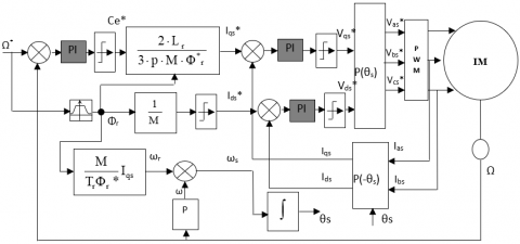
4.1 Modeling the induction motor for its control
Since the induction motor has the advantage of being robust, inexpensive and simple construction. However, this simplicity comes great physical complexity related to electromagnetic interaction between the stator and the rotor. Moreover, to develop control approaches ensuring the hoped performance, we need a model that reflects the operation of the machine so that transient steady [11, 12].
Figure 1. Speed control block by the indirect method
4.2 Simulation result and analysis
To illustrate the high efficiency induction motor performance, in this section MATLAB/ Simulink results are presented. We will compare the operating and characteristics of the 2.2 kW induction motor and analogous high efficiency (HE) via vector control in dynamic and static regimes.
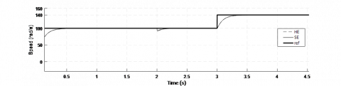
Since the objective of this work is to compare the control strategies, it is necessary to make a comparison of transitory and steady state regime. Operating conditions (reference speed 157 rad/sec, 100 rad/sec and 140 rad/sec. Load torque 15 Nm, simulation time 5 sec). As a final point, current and torque ripples will be evaluated and compared for different speed values and the constant torque.
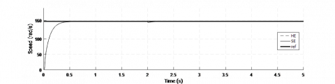
Figure 2 shows the induction motor (IM) speed setting by the indirect vector control.
a- Speed response
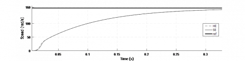
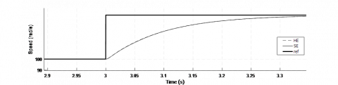
b- Zoom rise time ed speed response
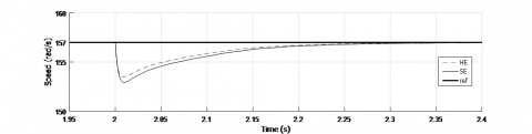
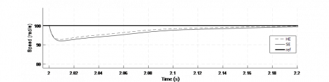
c- Zoom disturbance rejection ed speed response
Figure 2. Speed responses
Figure (2. a, b, c) illustrate the difference between the high efficiency (HE) induction motor and standard efficiency (SE) induction motor. The results show that by a high efficiency (HE) induction motor gives satisfactory results:
- The speed of rotation follows the reference speed without exceeding.
- The control ensures good regulation with disturbance rejection of 3.61 rad/s.
- A response time of 0.45 ms to reach the balanced state.
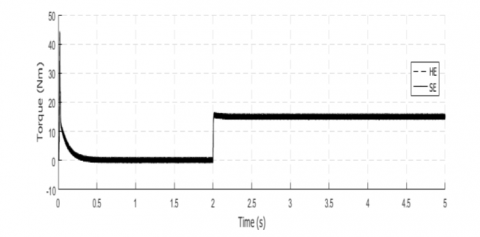
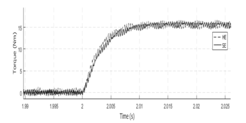
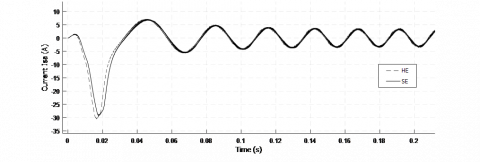
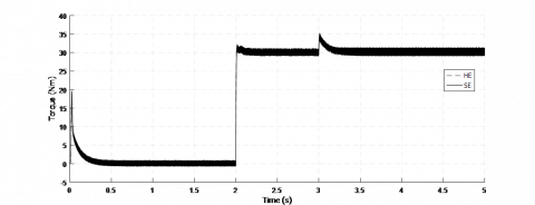
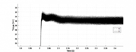
Figure 3 and Fig. 4, proves the induction motor torque and current setting by the indirect vector control.
a- Torque response
b- Zoom ed torque response at startup time
c- Zoom ed torque response at steady state
Figure 3. Torque responses
Figure (3. a, b, c) and Figure (4. a, b, c) shows the difference between the high efficiency (HE) induction motor and standard efficiency (SE) induction motor. These findings seem to indicate a misalignment of performance by a high efficiency (HE) and standard efficiency (SE).
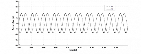
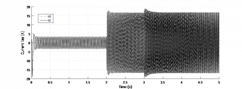
Figure 4 illustrate as the induction motor and at the same time the consumption of line currents is greater and the latter is negative because it increases the problem of engine operation and the protection devices cost.
a- Current response
b- Zoom ed current response at startup time
c- Zoom ed current response at steady state
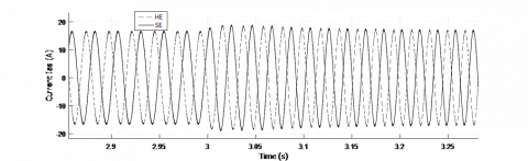
Figure 4. Current responses
In Figure (4.a), it is also possible to observe a diminution of the current when starting the motor with star, connection mainly due to the (HE) induction motor impedance higher, gives better quality of energy, a better estimation of physical quantities.
Figure (4. b, c) show again slightly better performances when standard efficiency (SE) induction motor is used. These results prove that high efficiency (HE) methods are not clearly superior to standard efficiency (SE) induction motor from the system performance perspective.
To prove the robustness of the developed control, we will proceed to the variation reference abruptly. Through the results of the following figures, there is a persistence of the claim, but the high-efficiency machine performance remains better.
a- Speed response
b- Zoom disturbance rejection ed speed response
c- Zoom disturbance rejection ed speed response
Figure 5. Robustness test
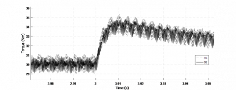
To check the starting capacity and the overload, the load torque is changed suddenly for t = 2s and at time t = 3s. The following figure shows this dynamic performance.
In Figure (6. b, c), a zoom of Figure (6. a) was presented. It can be make out that the high efficiency machine has a better capacity either in a transient state or in a steady state, so it confirms what is acknowledged in literature.
a- Torque response
b- Zoom ed torque response at startup time
c- Zoom ed torque response (140rad/s) applied at 3 seconds
Figure 6. Torque responses
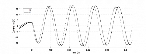
In the following figure, there is an increase in the call current following the increase load torque. So, despite the change of the reference speed the current remains sinusoidal but with some phase shift. This phase shift is mainly due to the difference between the parameters for the two machines.
a- Current response
b- Zoom ed current response (100 rad/s) applied at t=2s
c- Zoom ed current response (140 rad/s) applied at t=3s
Figure 7. Current response with the reference change
An indirect control scheme was proposed in this paper for an induction motor speed control to reduce the sensitivity to parameter variations disturbances; in the control scheme.
This paper provides study, simulation and analyses on the performance of standard efficiency (SE) and high efficiency (HE) induction motor. It can be observed that high efficiency (HE) induction motor shows a quick dynamic response to the speed of small speed set point changes as well as to load variations but has quite amount of torque ripples and current ripples. Since standard efficiency (SE) is complex and involves higher cost in implementation. High efficiency (HE) induction motor can be suggested in applications that require high dynamic response and small speed but with tolerable torque and current variations.
|
Parameters |
Meaning |
|
$v_{a s}, v_{b s}, v_{c s}$ |
the three stator voltages |
|
$i_{\text {as}}, i_{\text {bs }}, i_{\text {cs }}$ |
the three stator currents |
|
$v_{\mathrm{qs}}, v_{\mathrm{ds}}$ |
q-axis, d-axis stator voltage |
|
$v_{\mathrm{qr},} \boldsymbol{v}_\mathrm{ds}$ |
q-axis, d-axis rotor voltage |
|
iqs , ids |
q-axis, d-axis stator current |
|
iqr , idr |
q-axis, d-axis rotor current |
|
$\varphi_{q s}, \varphi_{d s}$ |
q-axis, d-axis stator flux linkage |
|
$\varphi_{q r}, \varphi_{d r}$ |
q-axis, d-axis rotor flux linkage |
|
$\dot{\theta}_{s}$ |
Electrical angular synchronous frequency |
|
$\dot{\theta}_{r}$ |
Electrical angular rotor frequency |
|
Ce |
Electromagnetic torque |
[1] Chekroun, S., Abdelhadi, B., Benoudjit, A. (2014). A new approach design optimizer of induction motor using particle swarm algorithm. AMSE JOURNALS-2014-Series: Modelling A, 87(2): 89-108.
[2] Zeghba, O., Chakroune, S., Belhamdi, S. (2018). Multi objective design of high efficiency induction motor using an analytical method's. Modelling, Measurement and Control A, 91(4): 202-211. https://doi.org/10.18280/mmc_a.910406
[3] Boglietti, A., Cavagnino, A., Lazzari, M., Pastorelli, M. (2003). 38th IAS Annual Meeting on Conference Record of the Industry Applications Conference, Salt Lake City, UT, USA, pp. 841-848. https://doi.org/10.1109/IAS.2003.1257626
[4] Calzada-Lara, G. (2016). Energetic consumption improvement in induction motors with possible mechatronics applications. Mechanics Based Design of Structures and Machines, 44(1-2): 137-145. https://doi.org/10.1080/15397734.2015.1104511
[5] Williamson, S., Fellow, I., Mc Clay, C. (1996). Optimization of the geometry of closed rotor slots for cage induction motors. IEEE Trans. Industrial Electronics, E-32(3): 560-268. https://doi.org/10.1109/28.502167
[6] Kim, G.S., Ha, I., Sam-KO, M. (1992). Control of induction motors for both high dynamic performance and high power efficiency. IEEE Trans. Industrial Electronics, 39(4): 323-333. https://doi.org/10.1109/41.149750
[7] Chang, J.H., Kook-Kim, B. (1997). Minimum-time minimum-loss speed control of induction motors under field-oriented control. IEEE Trans. Industrial Electronics, E-44(6): 809-815. https://doi.org/10.1109/41.649942
[8] Chekroun, S., Benoudjit, A., Abdelhadi, B. (2008). Application of genetic algorithms to optimization of induction motor design. 5th Conference CEE'08 Proceeding, Batna university, Algeria, 20-25, 27-29.
[9] Liwschitz, M., Maret, L. (1967). Calcul des Machines Electriques. Tome 1, Tome 2, Edition Dunod.
[10] Lakhdari, L., Bouchiba, B. (2018). Fuzzy sliding mode controller for induction machine feed by three level inverter. International Journal ox f Power Electronics and Drive System, 9(1): 25-63. https://doi.org/10.11591/ijpeds.v9n1.pp55-63
[11] Belhamdi, S., Goléa, A. (2017). Direct field-oriented control using fuzzy logic type-2 for induction motor with broken rotor bars. AMSE JOURNALS-2017-Series: Advances C, 72(4): 203-212. https://doi.org/10.18280/ama_c.720101
[12] Derouich, A., Lagrioui, A. (2014). Real-time simulation and analysis of the induction machine performances operating at flux constant. International Journal of Advanced Computer Science and Applications, 5(4): 59-64. https://doi.org/10.14569/IJACSA.2014.050410