Hung Bui Duc | Dinh Bui Minh | Bao Doan Thanh![]() | Tu Pham Minh | Vuong Dang Quoc*
| Tu Pham Minh | Vuong Dang Quoc*![]()
© 2023 IIETA. This article is published by IIETA and is licensed under the CC BY 4.0 license (http://creativecommons.org/licenses/by/4.0/).
OPEN ACCESS
The torque ripple, vibration and noise generated in interior permanent magnet synchronous machines (IPMSMs) due to the cogging torque. This will directly influence on the performance of the motors in general and IMMSMs in particular. Hence, the computation and investigation of the cogging torque play an important role for manufactures and designers to design the electric motors. In this paper, the analytical model of skew slot stators (SSSs), one-direction step-skew rotor (1D-SSR) and two-direction step skew rotor (2D-SSR) is presented to reduce the cogging torque of the IPMSMs. Then, the FEM is proposed to analyze and simulate the magnetic flux density, back electromotive force (EMF) and electromagnetic torque. However, in order to minimize the total harmonic distortions of the back-EMF waveforms due to the use of skew step rotors, a combination of the two-direction segment rotor structure with an optimal skewing angle of the 2D-SSR will be presented. A practical motor is applied to validate the developed method. The obtained results from the simulatated method are finally compared with the measured method.
interior permanent magnet synchronous motor (IMMSM), one direction step-skew rotor (1D-SSR), two-direction step skew rotor (2D-SSR), back eletromotive force (EMF), torque ripple, finite element method (FEM)
Many methods of the step-skew rotor have been recently proposed to reduce the torque ripple, noise and vibration, and improve the electromagnetic parameters of electric machines. In the study [1], the combination of different numbers of stator and rotor poles was presented to suppress the torque ripple. In the study [2], a finite element method (FEM) was developed for the interior permanent magnet synchronous machine (IPMSM) with 6 poles and 36 slots to reduce the cogging torque. In this paper, the combination of pole arc coefficient was studied. In the study [3], the axial flux permanent magnet machine (AFPMM) was proposed to design the slotted axial field flux switching for reducing the torque ripple. This paper also used the FEM to design, analyze and create the new model of machines. In the study [4], the traditional skewing, radial pole shaping and the proposed axial pole shaping were also used for a commercial industrial IPMSM to reduce the torque ripple. The obtained results were shown the reduction of the torque ripple effectively compared to other conventional techniques. In the study [5, 6], the shape of the magnets were developed with 2D radial flux motors for reducing the cogging torque of the AFPMM. In this paper, the 2D model was expanded to 3D one to take the new cogging torque cancellation conditions into account. The obtained results from the proposed method were also validated to the measured results. In the study [7], the hybrid excited axial field flux-switching permanent magnet (PM) machine is investigated for reducing the cogging torque reduction. The paper also indicated the influence of the machine design parameters on the field regulation capacity and output torque of the proposed machine. In the study [8], the cogging torque and torque ripple components of permanent magnet synchronous machines (PMSMs) were considered at low speeds with a new two-stage harmonic current injection technique. In this approach, the algorithm was developed to validate for two different AFPMMs experimentally. In the study [9], the cogging torque of permanent magnet machines (PMMs) was studied based on harmonic torque counteract. In this research, the FEM was proposed to investigate the influence of the current harmonic injection scheme on the dynamic cancellation of cogging torque and harmonic torque. Based on that, the use of different slots and poles of the PMM was shown to demonstrate the cogging torque reduction. In the study [10-12], the cogging torque components in double-rotor AFPMMs were minimized by several cost-effective magnet-skewing techniques. The obtained results demonstrated that the use of magnet-skewing approaches gave the cogging component reduction compared to one with un-skewed magnets.
In this research, the analytical model of skew slot stators (SSSs), one-direction step-skew rotor (1D-SSR) and two-direction step skew rotor (2D-SSR) is presented to reduce the cogging torque of the IPMSMs. Then, the FEM is proposed to analyze and simulate the magnetic flux density, electromagnetic torque and back electromotive force (EMF). But, the two-direction segment rotor structure is associated with an optimal skewing angle of the 2D-SSR to minimize the total harmonic distortions of the back-EMF waveforms due to the use of skew step rotors. The proposed method is validated on the practical motor to show a good agreement theory.
The sections of this paper are structured as follows. In Section 2, an analytical calculation of the different step skewed rotors and stator with different angles is introduced. Based on that the expression of the cogging torque, skewed factors, the SSS, 1D-SSR and 2D-SSR are respectively presented in Section 2.1, Section 2.2 and Section 2.3. The obtained results from the FEM will be then shown in Section 3. The 2D-SSR prototype is also given in Section 4. A conclusion is finally pointed out in Section 5.
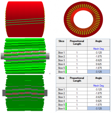
As presented in Section I, the torque ripple reduction is performed via the three models of SSS, 1D-SSR and 2D-SSR as shown in Figure 1. The 1D-SSR is the conventional method used in industrial applications, whereas the 2D-SSR with different skewing angle is developed in this research. To manufacture and assembly 6 slices together, a mechanical angle is created to guide 6 slices in the correct position.
Figure 1. Model of SSS (top), 1D-SSR (middle) and 2D-SSR (bottom)
2.1 Model of SSS
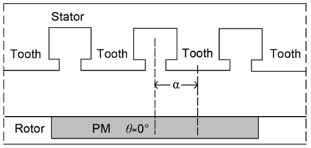
The relative position of rotor and stator of an IPMM is presented in Figure 2. Where the θ is the position of a specified PM, α is the angle between the centre line of the PM and the centre line of the stator tooth.
Figure 2. The typical model of rotor and stator
The cogging torque expression is defined via the magnetic energy variation (Wms) generated by the alternation between slots and teeth stored in the air gap, that is [1]
$T_{\operatorname{cog}}=-\frac{\partial W_{m s}}{\partial \alpha}$ (1)
where, the $W_{m s}$ is defined as
$W_{m s}=\frac{1}{2 \mu_0} \int_V B_m^2(\theta, \alpha) d V$ (2)
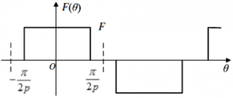
where, $\mu_0$ is the magnetic permeability and $B_m$ is the magnetic flux density of the PM, which varies with the position of the slot openings to θ as presented in Figure 3. Therefore, the Bm can be defined via the MMF (F):
$B_m=\frac{\mu_0}{\delta(\theta, \alpha)+h_{P M}} F(\theta)$ (3)
where, $\delta(\theta, \alpha)$ is the length of effective air gap along the circumference, $h_{P M}$ is the thickness of PM and $F(\theta)$ is the air gap distribution of MMF presented in Figure 3 [1, 6].
By substituting (3) into (2), one gets
$\begin{aligned} W_{m s}= & \frac{1}{2 \mu_0} \int_V B_m^2(\theta, \alpha) d V =\frac{1}{2 \mu_0} \int_V\left(\frac{\mu_0}{\delta(\theta, \alpha)+h_{P M}}\right)^2 F^2(\theta) d V\end{aligned}$ (4)
where, $F^2(\theta)$ is expressed via the Fourier series, i.e., [1].
Figure 3. The magnetomotive force (MMF) waveform along the circumference
$F^2(\theta)=F_0+\sum_{n=1}^{\infty} F_n \cos 2 n p \theta$ (5)
where, the terms $F_0=\alpha_p F^2$ and $F_n=\frac{2}{n \pi}\left(\frac{h_{P M} \, B_r}{\mu_0}\right)^2 \sin n \pi \alpha_p$.
The terms $\beta_r$ and $\alpha_p$ are respectively the remanent magnet and the pole-arc coefficient. By substituting the Eq. (5) into the Eq. (4) and the Eq. (4) into the Eq. (1), the cogging torque can be then defined as [1, 5]:
$T_{\operatorname{cog}}=\frac{\pi L_a}{2 \mu_0}\left(R_1^2-R_2^2\right) \sum_{j=1}^{\infty} F_n B_m \operatorname{sinjt\alpha }$ (6)
where, La is the axial length of the machine, R1 and R2 are respectively the radius of outer and inner stators, t is the number of stator slots and j is the positive integer. The skew factor (ksk) influenced directly on the cogging torque can be given [12-15]:
$k_{s k}=\frac{\sin \left(j \cdot \pi \cdot t \cdot \frac{\alpha_{s k}}{N}\right)}{j \cdot \pi \cdot t \cdot \frac{\alpha_{s k}}{N}}$ (7)
where, N is the number of slices and $\alpha_{s k}$ is the skew angle, which depends on the parameters of the rotor lamination shape, magnet shape, air-gap length, pole arc and width, and ratio of N/p. This makes clear that the cogging torque value is influenced directly on selecting the optimal parameters of the motor.
2.2 Model of 1D-SSR
The SSS with an angle shift of mechanical degrees (β) is considered for reducing the cogging torque. For that, the cogging torque expression can be defined via the rotor position [14]:
$T_{\operatorname{cog}}=\sum_{i=0}^n T_{c i} \sin (j N(\theta-\beta))$ (8)
If the stator is split into n segments along the motor axial direction, and βn is the angle shift of mechanical degree between the adjacent two rotor poles, the cogging torque is defined as [14]:
$T_{\operatorname{cog}}=\sum_{i=1}^n T_{c i} \sum_{j=o}^{n-1} \sin \left(i N\left(\theta-j \beta_n\right)\right)$ (9)
The above equation can be simplified to:
$T_{\operatorname{cog}}=\frac{1}{n} \sum_{i=1}^n T_{c i} \frac{\sin \frac{i N \beta_n n}{2}}{\sin \frac{i N \beta n}{2}} \sin \left(i N\left(\theta-j \beta_n\right)\right)$ (10)
If the i-order cogging torque is eliminated, the βn is theoretically expressed as the following requirements:
$\sin \frac{i N \beta_n n}{2}=0$ (11)
2.3 Model of 2D-SSR
The step skew factor ($k_{\text {skew_pole_v }}\quad$) of harmonic components of back EMF can be expressed [15-17]:
$k_{\text {skew_pole } \_v}=\frac{\sin \left(\frac{n v \cdot \alpha}{2(n-1)\,\,}\right)}{n \cdot \sin \left(\frac{v \cdot \alpha}{2(n-1)\,\,}\right)}$ (12)
where, n is the step number, α is the step skew angle and ν is the order number of harmonics. The factors of PM torque ($\mathrm{K}_{\mathrm{T} \text { _skew_pole_PM }}\quad$) and reluctant torque ($\mathrm{K}_{\mathrm{T} \text { _skew_pole_RE }}\quad$) are respectively given as:
$k_{T_{-} \text {skew_pole_PM }}\quad=\frac{\sin \left(\frac{n \cdot \alpha}{2(n-1)\,}\right)}{n \cdot \sin \left(\frac{\alpha}{2(n-1)\,}\right)}$ (13)
$k_{T_{-} s k e w \_p o l e \_R E}\quad=\frac{\sin \left(\frac{n \cdot \alpha}{n-1}\right)}{n \cdot \sin \left(\frac{\alpha}{n-1}\right)}=k_{T_{-} s k e w \_p o l e \_P M}\quad\cos \frac{\alpha}{2}$ (14)
These factors are equal to factors of the slot-skewing, if n is infinitely great. Thus, the torque can be described as [5, 12]:
$\begin{gathered}T=\frac{3}{2} p n\left[\psi_m I_s k_{T_{-} \text {skew_pole_PM }}\quad \sin \beta\right]+ \frac{3}{2} p n\left[\frac{1}{2} I_S^2\left(L_d-L_q\right) k_{T_{-} s k e w \_p o l e \_R E}\quad\sin 2 \beta\right]\end{gathered}$ (15)
where, p is the number of pole pair, Is is the amplitude of stator current and ψm is the magnetic flux per pole of single step. Based on this equation, the PM and reluctant torque components will be reduced by using the 2D-SSR.
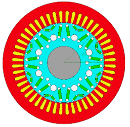
Three skewing magnet models are now applied. Firstly, the conventional skewing model with straight skewing getting a shift angle being smaller than the V shape skewing model with the same total skewing angle is considered. An IPM with 48 slots/8 poles and the IV shape of PM rotor is designed as shown in Figure 4. The main parameters are given in Table 1, where main differences are the winding overhang, slot opening and copper sizes of 15 (Φ 0.85) and 4, and the amplitude of phase current is 400 A. The opening width of slot filled winding is 1.2 mm being greater than the wire diamater of 1mm (Figure 2). The opening of stator slot is 5 mm being bigger than the size of rectangular bars of 4.3 mm x 3.3 mm.
Figure 4. Model of the IPM with 48 slots/8poles and IV shape of the PM rotor
Table 1. Parameters of filled slots and hairpin windings
|
Parameter |
Unit |
Values |
|
Continuous rated power |
kW |
150 |
|
Thickness of electrical steel sheet |
Mm |
0.2 |
|
The maximum speed |
Rpm |
12000 |
|
Stator lamination diameter |
mm |
250 |
|
Stator bore Ds |
mm |
175 |
|
Stator lamination length |
mm |
120 |
|
Magnet length |
mm |
120 |
|
Magnet segments |
|
6 |
|
Rotor lamination length |
mm |
100 |
|
Air gap |
mm |
1 |
|
Stator slot opening width (tS) |
mm |
1.2 |
|
Mechnical opening angle |
Degree |
0.55 |
|
Motor length |
mm |
240 |
|
winding overhang |
mm |
55 |
|
Copper size |
mm |
(Φ 0.85) |
|
Number Strands |
|
15 |
|
Phases: |
|
3 |
|
Turns: |
|
6 |
|
Throw: |
|
5 |
|
Parallel p. aths: |
|
2 |
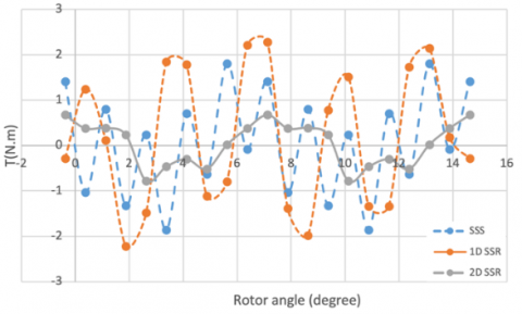
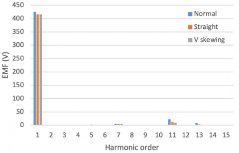
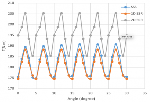
The distribution of magnetic flux density of 1/8 motor is shown in Figure 5. The cogging torque of three models with different rotor angles is presented in Figure 6. It can be seen that the value of the 2D-SSR design is the lowest because the second harmonic order is eleminated, while the value of the 1D-SSR design is the biggest. The back EMF waveforms of three models are presented in Figure 7. It can be analyzed by the fourrier transform with the harmonic orders (i.e, from first order to 15th orders) for the 2D-SSR as shown in Figure 8. It can be seen that the total harmonic distortions with the V skewing shape get the smallest value of 4.2% in comparison with the normal and straight shapes. The eletromagnetic torque distribution with with different rotor angles is pointed out in Figure 9. It obtains the hightest value for the 2D-SSR case and the smallest value for 1D SSR case.
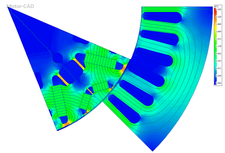
Figure 5. Magnetic flux density distribution of 1/8 motor
Figure 6. Cogging torque of three models with different rotor angles
Figure 7. Back EMF waveform of three models with different rotor angles
Figure 8. Harmonic order analysis of back EMF with three different cases
Figure 9. Electromagnetic torque waveform with different rotor angles
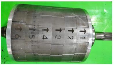
The rotor lamination prototype with six steps of V- skew magnet slices of the IPM motor (48 slots/8 poles) is manufactured as pointed out in Figure 10. The thickness of each segment is 20 mm with the skewed mechanical degree of 1.5°. For a no-load test, the back EMF comparison at the speed of 1500 rpm is shown in Figure 11. The rotational speed of 1500 rpm is one of operation point before going to a speed of 4500 rpm. The peak torque and output power performance under the speed range is from zero to the base speed.
Figure 10. Rotor lamination prototype with six steps of V-skew magnet slices
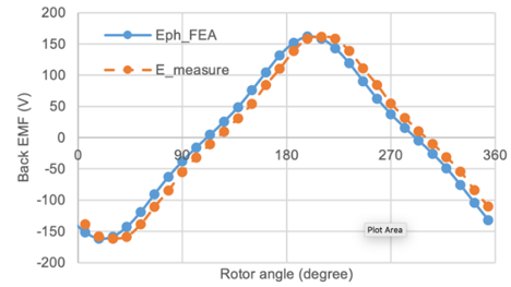
Figure 11. Back EMF comparison of simulated and measured results
In one period, it is measured by Osilloscope. The data files for plotting those curves are recorded. It shows that the simulated result is checked to be close the that obtained from the measured result, with the error being lower than 5%. The performance comparison of three models (SSS, 1D-SSR; 2D-SSR) is given in Table 2. For the 2D-SSR, the obtained output power and torque increase 8% in comparison with the case of the SSS and 1D-SSR, and 1.2% for the efficiency. However, the cogging torque is reduced 6% in comparison with the case of the SSS and 1D-SSR cases.
Table 2. Comparison results between the two methods
|
Parameters |
SSS |
1D-SSR |
2D-SSR |
Unit |
|
Average torque |
181.78 |
180.47 |
195.25 |
Nm |
|
Torque ripple |
15.878 |
13.693 |
19.912 |
Nm |
|
Torque ripple [%] |
8.7092 |
7.576 |
10.183 |
% |
|
Cogging Torque |
0 |
4.2056 |
3.7937 |
Nm |
|
Limitation speed |
6036.8 |
6157.8 |
5521.2 |
rpm |
|
No load speed |
7519.5 |
6991.8 |
6961.6 |
rpm |
|
Input power |
1.16E+05 |
1.15E+05 |
1.25E+05 |
Watts |
|
Total losses |
2545.3 |
2545.7 |
2625.5 |
Watts |
|
Output power |
1.14E+05 |
1.13E+05 |
1.22E+05 |
Watts |
|
System efficiency |
97.812 |
97.793 |
97.893 |
% |
|
Shaft torque |
181.11 |
179.51 |
194.19 |
Nm |
In this research, the 2D-SSR has been presented to estimate the magnetic flux density, back EMF waveform, harmonic components and torque ripple in the proposed PM motor. The results of the back EMF and cogging torque have shown a good agreement comparison between the FEM and measured method. In particular, the analytical calculation of V skewing angle for elemination double harmonic orders of the back EMF is significantly obtained. The prototype of V skewing magnet shape of IPM motor with the hairpin windings has been also designed and manufactured. The obtained results from the proposed method of the IPM motor of 150kW is the peak torque of 300 Nm at the base speed of 4500 rpm. The back EMF waveforms of the two methods have been pointed out to validate the suitable theory. Finally, the proposed method has the potential application value for manufacturing cost and scaling power by adding more modular.
This research is funded by Hanoi University of Science and Technology under project number T2022-PC-009.
[1] Wu, L., Ming, G., Zhang, L., Fang, Y. (2020). Improved stator/rotor-pole number combinations for torque ripple reduction in doubly salient PM machines. IEEE Transactions on Industrial Electronics, 68(11): 10601-10611. https://doi.org/10.1109/TIE.2020.3032926
[2] Liu, F., Wang, X., Xing, Z., Yu, A., Li, C. (2021). Reduction of cogging torque and electromagnetic vibration based on different combination of pole arc coefficient for interior permanent magnet synchronous machine. CES Transactions on Electrical Machines and Systems, 5(4): 291-300. https://doi.org/10.30941/CESTEMS.2021.00034
[3] Baig, M.A., Ikram, J., Iftikhar, A., Bukhari, S.S.H., Khan, N., Ro, J.S. (2020). Minimization of cogging torque in axial field flux switching machine using arc shaped triangular magnets. IEEE Access, 8: 227193-227201. https://doi.org/10.1109/ACCESS.2020.3044922
[4] Du, Z.S., Lipo, T.A. (2019). Reducing torque ripple using axial pole shaping in interior permanent magnet machines. IEEE Transactions on Industry Applications, 56(1): 148-157. https://doi.org/10.1109/TIA.2019.2946237
[5] Pristup, A.G., Toporkov, D.M. (2017). Comparing of cogging torque reduction methods in permanent magnet machines with fractional slot windings. IOP Conference Series: Earth and Environmental Science, 87(3): 032032. https://doi.org/10.1088/1755-1315/87/3/032032
[6] Simón-Sempere, V., Simón-Gómez, A., Burgos-Payán, M., Cerquides-Bueno, J.R. (2021). Optimisation of magnet shape for cogging torque reduction in axial-flux permanent-magnet motors. IEEE Transactions on Energy Conversion, 36(4): 2825-2838. https://doi.org/10.1109/TEC.2021.3068174
[7] Li, T., Slemon, G. (1988). Reduction of cogging torque in permanent magnet motors. IEEE Transactions on Magnetics, 24(6): 2901-2903. https://doi.org/10.1109/20.92282
[8] Xu, D., Li, N., Li, Q., Kong, Y., Lin, M. (2022). Investigation on the field regulation capacity in a hybrid excited axial field flux-switching permanent magnet machine for EV application. Energy Reports, 8: 696-703. http://doi.org/10.1016/j.egyr.2022.10.138
[9] Girgin, M.T., Guven, M.K., Aydin, M. (2021). A new harmonic current injection technique to reduce cogging torque in axial flux permanent magnet motors. IEEE Transactions on Magnetics, 58(2): 1-4. http://doi.org/10.1109/TMAG.2021.3087460
[10] Gao, J., Xiang, Z., Dai, L., Huang, S., Ni, D., Yao, C. (2021). Cogging Torque Dynamic Reduction Based on Harmonic Torque Counteract. IEEE Transactions on Magnetics, 58(2): 1-5. https://doi.org/10.1109/TMAG.2021.3093723
[11] Gulec, M., Aydin, M. (2014). Magnet asymmetry in reduction of cogging torque for integer slot axial flux permanent magnet motors. IET Electric Power Applications, 8(5): 189-198. http://doi.org/10.1049/iet-epa.2013.0256
[12] Aydin, M., Gulec, M. (2013). Reduction of cogging torque in double-rotor axial-flux permanent-magnet disk motors: A review of cost-effective magnet-skewing techniques with experimental verification. IEEE Transactions on Industrial Electronics, 61(9): 5025-5034. https://doi.org/10.1109/TIE.2013.2276777
[13] Zhao, W., Lipo, T.A., Kwon, B.I. (2015). Torque pulsation minimization in spoke-type interior permanent magnet motors with skewing and sinusoidal permanent magnet configurations. IEEE Transactions on Magnetics, 51(11): 1-4. https://doi.org/10.1109/TMAG.2015.2442977
[14] Caruso, M., Di Tommaso, A. O., Genduso, F., Miceli, R., Galluzzo, G.R. (2018). A general mathematical formulation for the determination of differential leakage factors in electrical machines with symmetrical and asymmetrical full or dead-coil multiphase windings. IEEE Transactions on Industry Applications, 54(6): 5930-5940. https://doi.org/10.1109/TIA.2018.2857474
[15] Caruso, M., Di Tommaso, A.O., Miceli, R., Rizzo, R. (2018). Computer-aided analysis and design procedure for rotating induction machine magnetic circuits and windings. IET Electric Power Applications, 12(6): 885-893. https://doi.org/10.1049/iet-epa.2017.0310
[16] Caruso, M., Di Tommaso, A.O., Marignetti, F., Miceli, R., Ricco Galluzzo, G. (2018). A general mathematical formulation for winding layout arrangement of electrical machines. Energies, 11(2): 446. https://doi.org/10.3390/en11020446
[17] Duc, H.B., Minh, D.B., Quoc, V.D. (2022). Analytical and FEM methods for line start permanent magnet synchronous motor of 2.2kW. Journal Européen des Systèmes Automatisés, 55(6): 715-721. https://doi.org/10.18280/jesa.550603