Ahmed Bahri* | Abdelkrim Thameur | Mourad Mordjaoui | Mohcene Bechouat | Moussa Sedraoui
© 2021 IIETA. This article is published by IIETA and is licensed under the CC BY 4.0 license (http://creativecommons.org/licenses/by/4.0/).
OPEN ACCESS
This paper presents an application of fractional control scheme named Tilt Integral Derivative (TID) to control a stand-alone hybrid energy system composed of a solar photovoltaic (PV) system and a battery bank (BB). A three-level NPC inverter is inserted in order to increase the efficiency of the energy injected into the AC load. Variation in solar radiation or AC load may cause power imbalance, which leads to variation in DC link voltage. As a solution, a buck-boost converter is connected between the DC link and the battery bank to ensures the transfer of energy in both directions. The parameters of TID controller were tuned using a powerful optimization technique known a Genetic Algorithm (GA) by minimizing the Mean Square Error (MSE) used as a performance index. The effectiveness of the proposed TID controller is demonstrated through a comparison with a conventional Proportional-Integral-Derivative (PID) controller, whose parameters are computed by the pidtool function of the Matlab/Simulink tool where the DC link voltage behavior is previously modeled by a capacitor transfer function. The obtained results show that the proposed TID controller provides a stable DC bus with low chattering, regardless of the rapid irradiation and load changes, when compared to a conventional PID controller.
battery bank, buck-boost converter, DC link voltage, genetic algorithm, photovoltaic system, Proportional-Integral-Derivative (PID), Tilt-Integral-Derivative (TID)
Because of the increased demand for energy consumption and the limited sources of fossil fuels in the world, the effective use of Renewable Energy (RE) is becoming more and more important. Furthermore, the increasing cost of limited sources and the difficulty to extract it along with the challenge of climate change have raised the need for renewable energy and have accelerated the transition to cleaner, more efficient electric power methods. There are several types of RE such as wind, solar, biomass and geothermal and each has its own merits and demerits [1-4].
Solar energy is the light and heat emitted from the sun converted to current by a device called a photovoltaic panel, where the photovoltaic cascades conversion fall into two categories: grid-connected systems and stand-alone. The latter configurations are applied in low power systems and require the battery bank to store the PV energy.
The power delivered by the PV system depend on two parameters: irradiance solar and ambient temperature [1-3]. Among the most famous applications, there is the autonomous system or called off-grid or Stand-alone abbreviated by “SPVS” used in several applications such as street lighting systems, remote areas and mobile military equipment for the desert and border-outpost [4].
Depending on the PV energy requirements for supplying the load, sizing is required for the overall PV system. So, to convert the maximum power of a PV system to the AC load, voltage must be adapted to it under changing solar irradiation. So, the connection of power electronic devices between the PV system and the battery in addition to the AC load plays an important role in achieving balance [5-7].
Researchers use different technical controls for DC-link voltage. For stand-alone mode, Samrat et al. have used a simple proportional-integral (PI) to control DC-link voltage [8-10]. However, Benlahbib et al. [11] achieved the control of the DC voltage link in a hybrid energy system composed of a turbine and batteries by a fractional order PID (FOPID), where the turbine is based on a permanent magnet synchronous generator (PMSG). In another research, control techniques such as sliding mode control was used [10]. In grid connected systems, a particle swarm optimization (PSO) was used to set the PI parameters [12]. In contrast, the authors in this paper used for the first time an optimal TID controller to regulate the DC link voltage in a DC-DC buck-boost converter connected to a lead acid battery bank. its parameters were determined using a meta-heuristic optimization technique such as a Genetic Algorithm (GA).
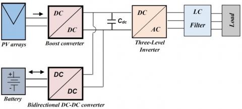
This paper uses the performance of the hybrid PV/battery system to satisfy the load requirements under any meteorological condition. The PV system and the batteries bank are coupled to the DC Bus through boost and reversible Buck-Boost converters respectively. A three phase three-level inverter (NPC) is the static converter used to feed the load. The proposed PV/Battery block is shown in Figure 1.
The first part in this paper presents an algorithm of Maximum Power Point tracking (MPPT) called the perturbation and observation (P&O) method applied to the PV system to extract maximum power by increasing or decreasing the duty cycle D through a Boost converter.
Secondly, a control technique is applied to charging/discharging the battery through a Buck-Boost Converter (BBC) to keep the DC link voltage stable during variations in load demand or source power. By controlling the DC link voltage, this control technique ensures the power balance in the system. A DC link voltage connected with DC-DC converters interface the PV panels with the battery [13, 14].
Finally, as we mentioned previously, the three-level inverter NPC is used to feed the AC load by a LC filter (Figure 1), which serves to reduce the high-frequency harmonics [14, 15].
The proposed PV/battery hybrid system was modeled, managed, simulated and validated under Matlab/Simulink tool. Furthermore, the results obtained are listed to verify the effectiveness under variable meteorological conditions [8]. Thus, the authors propose an optimal TID control to regulate the DC-link voltage through a two-quadrant buck-boost DC-DC converter integrated in the proposed system mounted exactly with the battery. Here, the TID control takes the variations of solar radiation and load into account to ensure robustness.
Figure 1. The proposed block PV/Battery
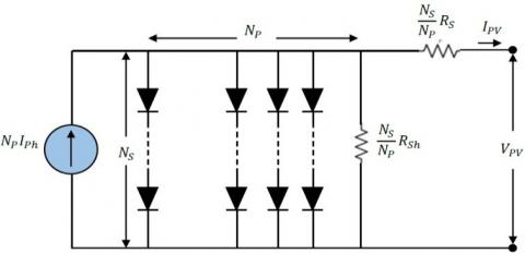
Figure 2. Equivalent circuit of the PV module
In general, the PV cell is often made of a semiconductor material such as silicon, germanium, gallium, arsenide, etc. It can therefore absorb the light energy and convert it into electrical current, where its characteristics are varied according to two weather conditions: solar radiation and absolute temperature. Indeed, in the modeling step of actual PV cell behavior, several PV models have been proposed [9, 10]. Among them, the equivalent electrical circuit, shown in Figure 2, is the most widely one used for computing the predicted current model $I_{p v}$ [16-19].
Two resistances and a $\mathrm{N}_{\mathrm{P}}$ diode is available. The shunt resistance $\frac{\mathrm{N}_{\mathrm{S}}}{\mathrm{N}_{\mathrm{P}}} \mathrm{R}_{\mathrm{sh}}$ illustrates the loss, which is a tiny leakage current that flows through the parallel part (Order of $\mathrm{k} \Omega$ ), the series resistance connection $\frac{\mathrm{N}_{\mathrm{S}}}{\mathrm{N}_{\mathrm{P}}} \mathrm{R}_{\mathrm{S}}$ (approximately $1 \Omega$ ) [20]. Number of cells in series is denoted Ns and in parallel Np, the relationship between the output current $\mathrm{I}_{\mathrm{pv}}$ and the voltage $\mathrm{V}_{\mathrm{pv}}$ is written as [4, 21-23]:
$\begin{gathered}
I_{p v}=N_{P} I_{p h}-N_{P} I_{s}\left(e\frac{\frac{v_{p v}}{N_{s}}+\frac{R_{s}}{N_{P}} I p v}{A\cdot^{\frac{K \cdot T}{q}}}-1\right) \\
-\frac{N_{p} V_{p v}+R_{s} N_{s} I_{p v}}{N_{s} R_{p}}
\end{gathered}$ (1)
where:
The generated photocurrent $\mathrm{I}_{\mathrm{ph}}$ and Saturation current $\mathrm{I}_{\mathrm{s}}$ are given respectively by:
$I_{p h}=\frac{s}{1000}\left(I_{s c}+K_{i}(T-295.15)\right)$ (2)
$I_{S}=I_{R S}\left[\frac{T}{295.15}\right]\left(e^{\frac{q E_{g}}{A \cdot K}\left(\frac{1}{295.15}-\frac{1}{T}\right)}\right)$ (3)
where: $\mathrm{K}=1.38 \times 10^{-23} \mathrm{j} / \mathrm{k}$ is Boltzmann constant.
The parameters of PV cell are summarized in the Table 1.
Table 1. PV cell parameters
|
Parameter |
Denomination |
Unit |
|
$q=1.6 \times 10^{-19}$ $T$ $V_{p v}$ $A$ $S$ $K_{i}$ $I_{R S}$ Eg |
Charge of electron Cell temperature Cell output voltage Quality factor Solar irradiance Current coefficient Reverse saturation current Band Gap energy |
C Kelvin V / $\mathrm{W} / \mathrm{m}^{2}$ / A ev |
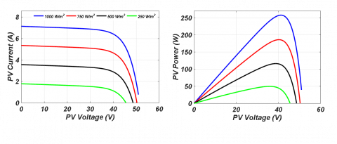
Figure 3. Characteristics of Sanyo HIB-225HDE1 under varying irradiation
The Eqns. (1) to (3) show that the current generated by the PV array depends on solar irradiation.
Figure 3 shows power and current characteristics of the Sanyo HIB-225HDE1 under effect solar irradiance.
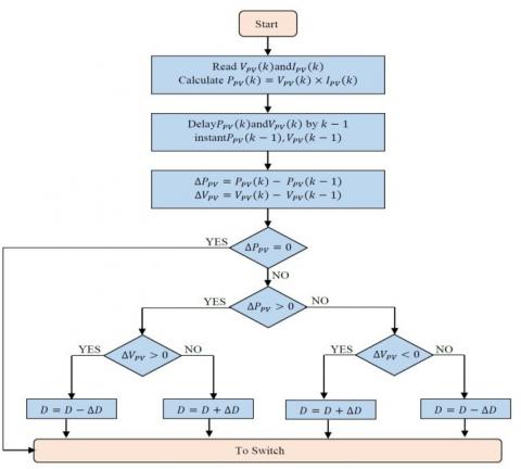
P&O is the first algorithm among the MPPT algorithms used in PV systems. To implement it in direct mode control, a duty cycle D and a sampling frequency are assigned at the beginning as illustrated in Figure 4 [8, 17, 18]:
Figure 4. P&O algorithm
$\begin{gathered}
\left\{\begin{array}{c}
\Delta V_{p v}=V_{p v}(k)-V_{p v}(k-1) \\
\Delta I_{p v}=I_{p v}(k)-I_{p v}(k-1) \text { and } \\
\Delta P_{p v}=P_{p v}(k)-P_{p v}(k-1) \\
\frac{\Delta P_{p v}}{\Delta V_{p v}}=\left\{\begin{array}{c}
=0, \text { at } M P O P \\
>0, \text { left } M P O P \\
<0, \text { right } M P O P
\end{array}\right.
\end{array}\right.
\end{gathered}$ (4)
Figure 5. Three phase three-level inverter NPC
Generally, the Three-Level Inverter NPC is attached between the DC link voltage and the load of the system. It used to regulate the voltage and frequency of the charge. Note here that our system is an off-grid, so the load voltage must be regulated in terms of frequency and voltage amplitude [8, 9]. The topology of a three-level inverter is illustrated in Figure 5, where the upper switches of the three-level inverter are $S_{k 1}, S_{k 2}$ in the ON state, which corresponds to the state $V_{\mathrm{dc} 1}^{\prime}$. If $S_{k 3}, S_{k 4}$ is on the lower switches, which corresponds to state' $-V_{\mathrm{dc} 2}$'. This results in condition '0' when the auxiliary switches are on $S_{k 3}, S_{k 4}$ [15].
The switch connection function FKS indicates the opened or closed state of the switch SKS, $F_{k s}=1$ when $S_{k s}$ close and $F_{k s}=0$ when $S_{k s}$ open (s=1, 2, 3, 4 and k=1, 2, 3)
The functions $\mathrm{F}_{\mathrm{km}}^{\mathrm{b}}$ of connection are given by:
$\left\{\begin{array}{l}
F_{k 1}^{b}=F_{k 1} \cdot F_{k 2} \\
F_{k 0}^{b}=F_{k 3} \cdot F_{k 4}
\end{array}\right.$ (5)
whereas:
m=1: The upper part of the NPC inverter works.
m=0: The lower part of the NPC inverter works.
Leg voltage $\mathrm{V}_{\mathrm{A} 0}, \mathrm{~V}_{\mathrm{B} 0} \text { and } \mathrm{V}_{\mathrm{CO}}$ can be written as:
$\left\{\begin{array}{l}
V_{A 0}=F_{11}^{b} \cdot V_{d c 1}-F_{10}^{b} \cdot V_{d c 2} \\
V_{b 0}=F_{21}^{b} \cdot V_{d c 1}-F_{20}^{b} \cdot V_{d c 2} \\
V_{C 0}=F_{31}^{b} \cdot V_{d c 1}-F_{30}^{b} \cdot V_{d c 2}
\end{array}\right.$ (6)
Simple output voltages are written as:
$\left[\begin{array}{c}
V_{A} \\
V_{B} \\
V_{C}
\end{array}\right]=\frac{1}{3}\left[\begin{array}{ccc}
2 & -1 & -1 \\
-1 & 2 & -1 \\
-1 & -1 & 2
\end{array}\right]\left\{\left[\begin{array}{l}
F_{11}^{b} \\
F_{21}^{b} \\
F_{31}^{b}
\end{array}\right] V_{d c 1}-\left[\begin{array}{c}
F_{10}^{b} \\
F_{20}^{b} \\
F_{30}^{b}
\end{array}\right] V_{d c 2}\right\}$ (7)
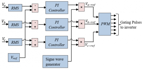
As AC loads are often single-phase in nature in the delivery system, the current would not be the same in various phases, and would not be equal in each phase because of the unbalanced load voltage attached to the inverter NPC. This unbalanced voltage drops at the level of the LC filters used at each phase, where the acceptable limit for the voltage unbalance factor is < 1%. To compensate for this voltage unbalance at the AC bus, the error between the Root Mean Square (RMS) of the voltages and the reference voltage is fed into the PI controller. The output of the PI controller is multiplied by a unit sine wave generator ( $V_{a-g e n}, V_{b-g e n}, V_{c-g e n}$ ). Using $V_{a-r e f}, V_{b-r e f} \text { and } V_{c-r e f}$, Pulse width Modulation (PWM) pulses are produced for the three-level NPC inverter to be turned on/off [24].
The function of the control scheme (Figure 6) is to separate modulation indexes for three phases in order to balance the unbalanced voltages on the AC bus [24, 25].
Figure 6. PWM of a three-phase three -level inverter
4.1 Battery modeling
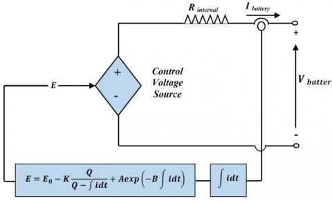
Out of all models available, the analogous circuit model is the most widely used for dynamic simulation. The battery has a high-energy capacity and can supply power at almost constant voltage if the cycles are properly regulated for charge/discharge. A lead-acid battery is utilized in this work, since it is more convenient for green systems due to its low cost and availability [13].
In our proposed system, the modeling of the battery was done with a constant resistive value of the controlled series attached voltage source shown in Figure 7 formulated by [8, 24]:
$\left\{\begin{array}{c}
E=E_{0}-K \frac{Q}{Q-\int i d t}+A \exp \left(-B \int i d t\right) \\
V_{\text {Battery }}=E-R_{\text {in }} I_{\text {Battery }}
\end{array}\right.$ (8)
where, the parameters are summarized in the Table 2.
Figure 7 shows the circuit of the implemented model of the battery in Matlab/Simulink tool [8, 9].
Table 2. Battery parameters
|
Parameter |
Denomination |
Unit |
|
E0 Q K A B VBattery Rin $\int \mathrm{idt}$ IBattery |
Constant voltage Battery capacity Polarization voltage Exponential voltage Exponential capacity Battery voltage Internal resistance Extracted capacity Battery current |
V Ah V V Ah-1 V $$ Ah A |
Figure 7. Non-linear typical battery model
Figure 8. The proposed block PV/Battery
4.2 Battery control strategy
In order to obtain the required power, it is essential to regulate the current generated by the battery. One must bear in mind the constraints related to the existing charge and discharge and the overall state of charge (SOC) limits. The following criteria must be reviewed by the SOC:
$\operatorname{SOC}_{\min } \leq \operatorname{SOC}(t) \leq \operatorname{SOC}_{\max }$ (9)
where, the maximum and minimum acceptable storage capacities are respectively, $\text { SOC }_{\min } \text { and } \operatorname{SOC}_{\max }$ .
The battery has an important role as an intermediate between the PV and the load. Generally, it has two operating states, namely: charging and discharging. To control the DC voltage, the BBC controller has two switches namely Q 1and Q2, where the working principle is detailed as follow:
Whatever the constraints or load variations, it is still held at a steady voltage [15].
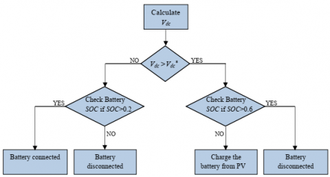
The proposed PV/Battery block is coupled with the three-level inverter to feed the three phase loads by a DC link voltage as shown in Figure 8 [8, 9, 24].
The BBC is used to maintain the value of the DC link voltage as desired and to ensure a charging or discharging of the battery according to the PV system (Figure 8). The block diagram of the controller is detailed in the same Figure 8. By using the controller in the simulation under Matlab/Simulink tool (detailed in section 5), the batteries must be connected in series to have a voltage lower than the reference DC link voltage (Vdc). In our proposed system the battrey voltage is fixed at 300V; this allows to choose $V_{d c}>300 \mathrm{~V}$ (our choice is $V_{d c}=700 \mathrm{~V}$). In this analysis, the battery discharge depth is considered to be 60%. Furthermore, it is expected that electrical power should be supplied to the 8 kW load.
Generally, the battery serves either as a load or as a power source, depending whether there is surplus or a loss of power. It can charge or discharge under defined limits according to weather conditions. In this analysis, due to high power conditions, surplus power is initially supplied to the battery bank before it exceeds its upper limit of storage capacity [26].
The flow chart in Figure 9 shows the above control coordination between the PV and battery, where the battery's lower and upper SOC limits are held at 0.2 and 0.6, respectively [24].
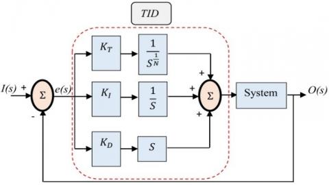
4.3 TID Controller
The TID corrector is a control system that improves the performance of a closed-loop system or process. The structure of the TID ($K_{T}, K_{I}, K_{D} \text { and } N$) is similar to that of PID $\left(K_{P}, K_{I}, \text { and } K_{D}\right)$, except that the proportional behavior is replaced by an inclined proportional behavior having a transfer function $\mathrm{S}^{-\frac{1}{\mathrm{~N}}}$. The inclined behavior provides a feedback gain according to the frequency, which is inclined relative to the gain / frequency of the conventional compensator. Thus, the whole compensator is called TID. A representation of a functional diagram of TID control is shown in Figure 10 [27-31].
Figure 9. DC link voltage control algorithm
Figure 10. TID controller bloc diagram
In Figure 10, the transfer function of the TID controller expressed in parallel form is given by:
$K(S, X)=\frac{K_{T}}{S^{\frac{1}{N}}}+\frac{K_{I}}{S}+K_{D} \cdot S$ (10)
4.4 GA Optimization
The desired TID controller has four variables, which are:
$X=\left(K_{T}, N, K_{I}, K_{D}\right)^{T}$ (11)
The optimal vector $\mathrm{X}^{*}$ is determined from minimizing the Mean Square Error (MSE) given by:
$J=\frac{1}{n} \sum_{i=1}^{n}\left(V_{d C}(i)-V_{d C_{-} \operatorname{simu}}(i)\right)^{2}$ (12)
where, Vdc is the reference desired DC link voltage, $V_{\text {dC_simu }}$ is the output DC link voltage given by simulation under Matlab/Simulink using GA algorithm generated by control parameters for n sampled points. This optimization problem is solved under the following constraints:
$\underbrace{\left[\begin{array}{c}
0 \\
2 \\
0 \\
0
\end{array}\right]}_{X_{\text {min }}} \leq\left[\begin{array}{c}
K_{T} \\
N \\
K_{I} \\
K_{D}
\end{array}\right] \leq \underbrace{\left[\begin{array}{c}
\operatorname{in} f \\
3 \\
i n f \\
i n f
\end{array}\right]}_{X_{\max }}$ (13)
The block diagram (see Figure 11) shows the controller optimization strategy:
Figure 11. Flowchart describing the tuning parameters of the TID controller by the GA
According to Figure 8, the discrepancy voltage, generated from comparing the two voltages $V_{d C} \text { and } V_{d C_{-s i m u}}$ is used to formulate the fitness function, given by Eq. (12). It is then transferred to the MATLAB software’s based on GA function, where its setting parameters are previously selected by the designer using some existing guidelines [32-34]. Then, the GA algorithm generates randomly initial populations where the fitness function is evaluated in each one. This yields also to providing the first optimal parameters of the TID controller. The three steps such as reproduction, crossing and mutation of populations are performed in order to find other optimal TID parameters better than those existing in the preceding populations. Next, a judgment test is performed to select the best solution, in which a proper attenuation of the fitness function is done. These steps are repeated as the stopping criterion is not reached. Finally, the GA is achieved by providing the best optimal solution that allowing to determine the TID transfer function. As a result, according to Figure 11, the GA step-procedures are summarized as follows:
initialization of population;
While the goal or the number of generations not obtained
Crossover step:
perform crossover between the bests parent chromosomes;
Mutation step:
evaluate fitness offspring after choose mutation points and perform mutation
Reproduction step:
create new population
End
Table 3 summarizes the tuning parameters of the GA function under Matlab/Simulink, which are the same used in [34].
Table 3. GA parameters
|
Parameter |
|
Value |
|
Programme execution Population size Generation number Reproduction
Mutation function
Crossover function Migration |
Elite count Crossover
Direction Fraction |
20 100 20 2 0.8 Constrain dependent Scattered Forward 0.2 |
In this section, the control loop is implanted in Matlab/Simulink software using the sampling time $\mathrm{T}_{\mathrm{s}}=10^{-5} \mathrm{~S}$; where the numerical values of the PV and the battery systems are summarized in Tables 4 and 5, respectively.
Table 4. PV Array parameters
|
Components |
Ratings values |
|
Module Type |
Sanyo HIP-225HDE1 |
|
Number of Cells |
60 |
|
Series module |
06 |
|
Parallel module |
06 |
|
Voc, Isc, Vmmp, Immp |
41.79V, 7.13A, 33.9V, 6.63A |
|
Rs, Rp, Isat, Iph, Qd |
00.204Ω,1830.7Ω,3.0815e-07A, 7.145A,1.6 |
The optimal values obtained of the TID are $\mathrm{K}_{\mathrm{T}}=21.0521, \mathrm{~N}=2.0089, \mathrm{~K}_{\mathrm{I}}=3.8001$ and $\mathrm{K}_{\mathrm{D}}=0.0299$ as shown in the fitness plots provided by the algorithm during the extraction process (Figure 12). The pidtool function is applied to provide the three PID gains $\mathrm{K}_{\mathrm{P}}=1.042, \mathrm{~K}_{\mathrm{I}}=355.5 \text { and } \mathrm{K}_{\mathrm{D}}=0$.
Table 5. Battery parameters
|
Components |
Ratings values |
|
Battery type Nominal voltage Capacity rating Initial state of charge |
Lead-Acid 300 V 6.5 Ah 60% |
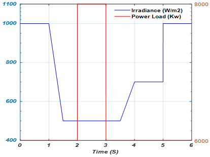
The robustness test was performed as shown in Figure 13:
Figure 12. The best obtained fitness curve through GA algorithm
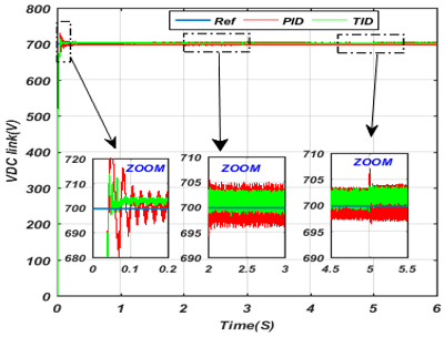
The robustness of the proposed controller was assessed under DC link fixed at 700 V during variation of irradiance and load. For this study, the response of the TID and PID controllers were taken into consideration. The DC link voltage shown in Figure 14 is nearly constant, but with some negligible variation due to the large delay between PV and load changes recovered by the battery as shown in Figure 15.
Figure 13. Irradiance and power load variations
Figure 14. DC link voltage of the PV/Battery system using TID and PID controllers
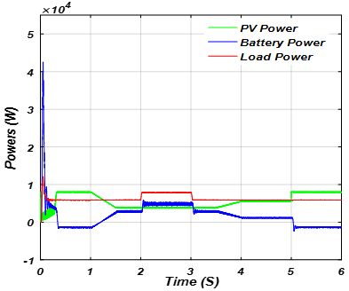
Figure 15. Powers distribution curve of PV/battery and load
According to Figure 14, one can clearly observe that the DC link voltage responses and the resulting control given by the TID controller are better than those provided by the PID controller. The superiority of the TID controller manifests itself in smooth DC link voltage response, less sensitivity against load power variations and elimination of the steady-state electrical power oscillation. In addition, it can be seen from Figure 15 that the BBC controller's output is very satisfactory because the battery bank power changes (charges/discharges) to maintain the balance of the system power under various irradiance and load conditions. In reality, if the AC load power is greater than the produced PV power, the BBC controller is programmed to discharge the power of battery into the AC load. In addition, the controller is also capable of charging the battery power when the load power is lower than the produced PV power.
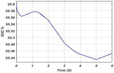
The peak power of the battery (Figure 15) in transitional regime is justified by a delay in the power supplied by the PV due to the influence of the MPPT algorithm, which depends on voltage and current to provide a maximum power. The SOC, as shown in Figure 16, is at 60% at the beginning, and then it decreased in transitional regime until 0.2 S before increasing until 1.25 S (charging period). Next, it is discharged up to 5 S (the case of increasing power load and decreasing PV power). Finally, it is charged again when the power load decreases and the PV power increases.
From the above results, it is easy to observe the effectiveness of:
Figure 16. State of Charge SOC of the battery
Figure 17. The output phase current and inverter voltage
Figure 18. Zoom of the output phase current and inverter voltage
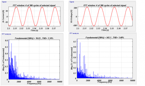
Figure 19. Spectrum analysis of current and voltage of the inverter
The current and voltage waveforms of the three level-inverter of the load when TID control is implemented are shown in Figure 17. There is also a zoom in on a small range as shown in Figure 18.
This result demonstrates the efficacy of the suggested three-level inverter control and the better quality of the supplied power.
To confirm that the two singles current and voltage produced by the NPC inverter for the proposed control are good, a Total Harmonic Distortion (THD) calculated (must be < 5%), were 1.74% and 1.49% (see Figure 19).
A comparative study based on the performance and robustness of the regulation of a DC link voltage in a hybrid system composed of a PV/battery system using PID and TID controllers has been presented in this paper. It was assessed for different changes in solar irradiance and power load. The TID controller parameters tuned by GA algorithm exhibit better performance and robustness than those offered by a PID controller. The optimal PID control depends on the transfer function by using pidtool function in Matlab/Simulink tool. The simulation results confirm that the TID control allows rapid tracking of the desired DC link voltage under various tests, also the oscillation problem is significantly reduced.
This work was supported by the Directorate-General for Scientific Research and Technological Development (DG-RSDT) of Algeria under PRFU project number: A10N01UN470120210001.
|
BB |
battery bank |
|
BBC |
Buck-Boost Converter |
|
GA |
Genetic Algorithm |
|
MPPT |
Maximum Power Point tracking |
|
MSE |
Mean Square Error |
|
NPC |
Neutral Point Clamped |
|
P&O |
perturbation and observation |
|
PID |
Proportional-Integral-Derivative |
|
PWM |
Pulse width Modulation |
|
RE |
Renewable Energy |
|
SOC |
state of charge |
|
TID |
Tilt Integral Derivative |
|
THD |
Total Harmonic Distortion |
|
Greek symbols |
|
|
$I_{p v}$ |
Photovoltaic current, A |
|
$\mathrm{I}_{\mathrm{ph}}$ |
Photocurrent, A |
|
$\mathrm{I}_{\mathrm{S}}$ |
Saturation current, A |
|
$\mathrm{V}_{\mathrm{pv}}$ |
Cell output voltage, V |
|
A |
Quality factor. |
|
q |
Charge of electron, C |
|
T |
Cell temperature, |
|
K |
Boltzmann constant, $1.38 \times 10^{-23} \mathrm{j} / \mathrm{K}$ |
|
S |
Solar irradiance, $\mathrm{W} / \mathrm{m}^{2}$ |
|
$\mathrm{K}_{\mathrm{i}}$ |
Current coefficient, |
|
$\mathrm{E}_{0}$ |
Constant voltage of battery, V |
|
Q |
Battery capacity, Ah |
|
$\mathrm{V}_{\text {Battery }}$ |
Battery voltage, V |
|
$\mathrm{I}_{\text {Battery }}$ |
Battery current, A |
|
B |
Exponential capacity, $\mathrm{Ah}^{-1}$ |
|
$\mathrm{V}_{\mathrm{dc}}$ |
DC link voltage, V |
|
$\mathrm{R}_{\mathrm{in}}$ |
Internal resistance, $\Omega$ |
|
Q1 |
Switch 1, |
|
Q2 |
Switch 2, |
|
$\int \mathrm{idt}$ |
Extracted capacity, Ah |
[1] Maleki, A., Rosen, M.A., Pourfayaz, F. (2017). Optimal operation of a grid-connected hybrid renewable energy system for residential applications. Sustainability, 9(8): 1314. https://doi.org/10.3390/su9081314
[2] Saad, N.H., El-Sattar, A.A., Mansour, A.E.A.M. (2018). A novel control strategy for grid connected hybrid renewable energy systems using improved particle swarm optimization. Ain Shams Engineering Journal, 9(4): 2195-2214. https://doi.org/10.1016/j.asej.2017.03.009
[3] Maleki, A., Hafeznia, H., Rosen, M.A., Pourfayaz, F. (2017). Optimization of a grid-connected hybrid solar-wind-hydrogen CHP system for residential applications by efficient metaheuristic approaches. Applied Thermal Engineering, 123: 1263-1277. https://doi.org/10.1016/j.applthermaleng.2017.05.100
[4] Thang, T.V., Ahmed, A., Kim, C.I., Park, J.H. (2015). Flexible system architecture of stand-alone PV power generation with energy storage device. IEEE Transactions on Energy Conversion, 30(4): 1386-1396. https://doi.org/10.1109/TEC.2015.2429145
[5] Mellincovsky, M., Yuhimenko, V., Zhong, Q.C., Peretz, M.M., Kuperman, A. (2018). Active DC link capacitance reduction in grid-connected power conversion systems by direct voltage regulation. IEEE Access, 6: 18163-18173. https://doi.org/10.1109/ACCESS.2018.2820095
[6] Philip, S., Preetha, P.K., Gopal, V.K. (2018). DC link voltage regulation of a battery integrated solar photo voltaic system. 2018 3rd IEEE International Conference on Recent Trends in Electronics, Information & Communication Technology (RTEICT), Bangalore, India, pp. 244-249. https://doi.org/10.1109/RTEICT42901.2018.9012220
[7] Penthia, T., Panda, A.K., Sarangi, S.K. (2018). Implementing dynamic evolution control approach for DC-link voltage regulation of superconducting magnetic energy storage system. International Journal of Electrical Power & Energy Systems, 95: 275-286. https://doi.org/10.1016/j.ijepes.2017.08.022
[8] Samrat, N.H., Ahmad, N., Choudhury, I.A., Taha, Z. (2015). Technical study of a standalone photovoltaic-wind energy based hybrid power supply systems for island electrification in Malaysia. PloS ONE, 10(6): e0130678. https://doi.org/10.1371/journal.pone.0130678
[9] Samrat, N.H., Ahmad, N.B., Choudhury, I.A., Taha, Z.B. (2014). Modeling, control, and simulation of battery storage photovoltaic-wave energy hybrid renewable power generation systems for island electrification in Malaysia. The Scientific World Journal. https://doi.org/10.1155/2014/436376
[10] Reddy, C.S.R., Kumar, K.R., Kalavathi, M.S. (2018). DC Link voltage regulation of a standalone hybrid power system. International Journal of Pure and Applied Mathematics, 118(24).
[11] Benlahbib, B., Bouchafaa, F., Bouarroudj, N., Mekhilef, S. (2019). Fractional order PID controller for DC link voltage regulation in hybrid system including wind turbine-and battery packs-experimental validation. International Journal of Power Electronics, 10(3): 289-313. https://doi.org/10.1504/IJPELEC.2019.099346
[12] Thameur, A., Noureddine, B., Abdelhalim, B., Boualam, B., Abdelkader, L., Karima, B., Tarak, B. (2020). Particle swarm optimization of pi controllers in grid-connected PV conversion cascade based three levels NPC inverter. 2020 IEEE International Conference on Environment and Electrical Engineering and 2020 IEEE Industrial and Commercial Power Systems Europe, (EEEIC/I&CPS Europe), Madrid, Spain, pp. 1-5. https://doi.org/10.1109/EEEIC/ICPSEurope49358.2020.9160704
[13] Villalva, M.G., De Siqueira, T.G., Ruppert, E. (2010). Voltage regulation of photovoltaic arrays: Small-signal analysis and control design. IET Power Electronics, 3(6): 869-880. https://doi.org/10.1049/iet-pel.2008.0344
[14] Vigneysh, T., Kumarappan, N. (2018). Dynamic modeling and control of utility-interactive microgrid using fuzzy logic controller. Intelligent and Efficient Electrical Systems, pp. 97-106. https://doi.org/10.1007/978-981-10-4852-4_9
[15] Koulali, M., Berkani, A., Negadi, K., Mankour, M., Mezouar, A. (2020). Sliding fuzzy controller for energy management of residential load by multi-sources power system using wind PV and battery. Journal Européen des Systèmes Automatisés, 53(3): 305-315. https://doi.org/10.18280/jesa.530301
[16] Ang, G., Arcibal, P.J., Crisostomo, L.M.R., Ostia Jr, C.F., Joaquin, P.J.C.S., Tabuton, J.E.C. (2017). Implementation of a fuzzy controlled buck-boost converter for photovoltaic systems. Energy Procedia, 143: 641-648. https://doi.org/10.1016/j.egypro.2017.12.740
[17] Mishra, J., Das, S., Kumar, D., Pattnaik, M. (2019). Performance comparison of P&O and INC MPPT algorithm for a stand-alone PV system. 2019 Innovations in Power and Advanced Computing Technologies (i-PACT), Vellore, India, pp. 1-5. https://doi.org/10.1109/i-PACT44901.2019.8960005
[18] Bechouat, M., Sedraoui, M., Feraga, C.E., Aidoud, M., Kahla, S. (2019). Modeling and fuzzy MPPT controller design for photovoltaic module equipped with a closed-loop cooling system. Journal of Electronic Materials, 48(9): 5471-5480.
[19] Aidoud, M., Feraga, C.E., Bechouat, M., Sedraoui, M., Kahla, S. (2019). Development of photovoltaic cell models using fundamental modeling approaches. Energy Procedia, 162(1): 263-274. https://doi.org/10.1016/j.egypro.2019.04.028
[20] Yilmaz, U., Kircay, A., Borekci, S. (2018). PV system fuzzy logic MPPT method and PI control as a charge controller. Renewable and Sustainable Energy Reviews, 81: 994-1001. https://doi.org/10.1016/j.rser.2017.08.048
[21] Rai, N., Rai, B. (2018). Control of fuzzy logic based PV-battery hybrid system for stand-alone DC applications. Journal of Electrical Systems and Information Technology, 5(2): 135-143. https://doi.org/10.1016/j.jesit.2018.02.007
[22] Tang, S., Sun, Y., Chen, Y., Zhao, Y., Yang, Y., Szeto, W. (2017). An enhanced MPPT method combining fractional-order and fuzzy logic control. IEEE Journal of Photovoltaics, 7(2): 640-650. https://doi.org/10.1109/JPHOTOV.2017.2649600
[23] Mohapatra, A., Nayak, B., Das, P., Mohanty, K.B. (2017). A review on MPPT techniques of PV system under partial shading condition. Renewable and Sustainable Energy Reviews, 80: 854-867. https://doi.org/10.1016/j.rser.2017.05.083
[24] Geetha, R., Angalaparameswari, G., Kumar, K.S., Sangeetha, A. (2018). Permanent magnet synchronous generator based wind energy battery storage system using nonlinear multi input multi output controller. International Journal of Pure and Applied Mathematics, 118(24).
[25] Hemmati, R., Azizi, N., Shafie-Khah, M., Catalão, J.P. (2018). Decentralized frequency-voltage control and stability enhancement of standalone wind turbine-load-battery. International Journal of Electrical Power & Energy Systems, 102: 1-10. https://doi.org/10.1016/j.ijepes.2018.04.021
[26] Chong, L.W., Wong, Y.W., Rajkumar, R.K., Isa, D. (2018). An adaptive learning control strategy for standalone PV system with battery-supercapacitor hybrid energy storage system. Journal of Power Sources, 394: 35-49. https://doi.org/10.1016/j.jpowsour.2018.05.041
[27] Topno, P.N., Chanana, S. (2016). Application of tilt integral derivative control on two-area power system. Journal of Engineering Research, 2(4): 1-15. https://doi.org/10.7603/s40632-016-0012-4
[28] Delassi, A., Arif, S., Mokrani, L. (2016). A novel tilt integral derivative plus second derivative order for load frequency control problem in power system. 2016 8th International Conference on Modelling, Identification and Control (ICMIC), Algiers, Algeria, pp. 359-363. https://doi.org/10.1109/ICMIC.2016.7804137
[29] Sain, D., Swain, S.K., Mishra, S.K. (2016). TID and I-TD controller design for magnetic levitation system using genetic algorithm. Perspectives in Science, 8: 370-373. https://doi.org/10.1016/j.pisc.2016.04.078
[30] Sahu, R.K., Sekhar, G.C., Priyadarshani, S. (2019). Differential evolution algorithm tuned tilt integral derivative controller with filter controller for automatic generation control. Evolutionary Intelligence, 14: 5-20. https://doi.org/10.1007/s12065-019-00215-8
[31] Sharma, P., Prakash, A., Shankar, R., Parida, S.K. (2020). A novel hybrid salp swarm differential evolution algorithm based 2DOF tilted-integral-derivative controller for restructured AGC. Electric Power Components and Systems, 47(19-20): 1775-1790. https://doi.org/10.1080/15325008.2020.1731870
[32] Kim, K., Shan, Y., Nguyen, X.H., McKay, R.I. (2014). Probabilistic model building in genetic programming: a critical review. Genetic Programming and Evolvable Machines, 15(2): 115-167. https://doi.org/10.1007/s10710-013-9205-x
[33] Vikhar, P.A. (2016). Evolutionary algorithms: A critical review and its future prospects. 2016 International Conference on Global Trends in signal Processing, Information Computing and Communication (ICGTSPICC), Jalgaon, India, pp. 261-265. https://doi.org/10.1109/ICGTSPICC.2016.7955308
[34] Bechouat, M., Younsi, A., Sedraoui, M., Soufi, Y., Yousfi, L., Tabet, I., Touafek, K. (2017). Parameters identification of a photovoltaic module in a thermal system using meta-heuristic optimization methods. International Journal of Energy and Environmental Engineering, 8(4): 331-341. https://doi.org/10.1007/s40095-017-0252-6