Aris Suryadi | Didik Notosudjono* | Dede Suhendi | Ubaedy Rachmat
© 2021 IIETA. This article is published by IIETA and is licensed under the CC BY 4.0 license (http://creativecommons.org/licenses/by/4.0/).
OPEN ACCESS
Electrical energy is a basic human need and its use continues to increase, it is necessary to seek and utilize alternative to meet these energy needs, among others, by combining wind energy and solar energy. In its application, this hybrid power plant requires a battery as a storage medium and a controller as a regulator. There is a controller designed for the direct control type, where the electrical energy from the power plant to the hybrid source will not be directly channeled to the battery but through the MOSFET first, so that charging and disbursement of power consumption on the battery can be regulated. When the battery is fully charged, the system voltage controller will read the parameters to be adjusted and will disconnect the hybrid power source to the battery to prevent overcharge. The controller switches and regulates battery power usage to the load. The battery charging control system uses the PWM method using a MOSFET as the driving circuit and the ATMega 32 microcontroller as the system controller.
windmill, solar panel, microcontroller, solar controller, battery
The need for energy in modern times continues to increase and electrical energy is the most widely used source of energy until it is used as a basic need, so it is demanded to find various kinds of alternative electrical energy to meet daily needs both on a household and industrial scale [1]. This alternative electrical energy must use new and renewable energy sources that are developed in its utilization because the energy sources produced are environmentally friendly [2], do not contribute to climate change and global warming and the amount is unlimited because the energy obtained comes from sustainable natural processes to minimize energy crisis by reducing the use of non- renewable fossil energy and petroleum so that at any time it can run out [3].
One example of using alternative electrical energy could be making a Hybrid Small Power Plant [4]. However, in its application, this alternative solar and wind power plant requires a storage medium to store electrical energy generated by using a battery according to the load and energy availability from the source used so that electrical energy can be used at a later time [5-7].
Based on the above issues will be made by the control system of charging the battery on Power Hybrid wind and photovoltaic using ATMega 32 as the brain controlling MOSFET as a series of drivers in the process of charging and in overcoming overcharging by regulating the process of charging when the battery voltage is below par and men - discharge power towards the battery when the battery is fully charged [8]. Then, the controller will also divert and regulate the power use of the battery to the load.
The hybrid system is defined as a power generation system that combines two or more generators with different energy sources, generally aiming to maximize energy at low prices, pollution-free, good power quality efficiently and optimally, to obtain synergies that provide economic benefits as well as technical [5].
2.1 Hybrid system
Power plant solar cell is an alternative power plant that uses sunlight as its energy source which is then converted into electrical energy using photovoltaic technology which is made from a semiconducting material called a solar cell [9].
2.2 Solar power plant (SPP)
SPP is an alternative power plant that uses sunlight as its energy source which is then converted into electrical energy using photovoltaic technology which is made from a semiconducting material called a solar cell [9].
2.2.1 Principle of solar cells
Solar cells can absorb sunlight which contains electromagnetic waves or photon energy. The energy of photons from sunlight produces kinetic energy that is capable of releasing free-moving electrons, in the presence of the transfer of electrons to produce an electric current. The electric current will increase when the intensity of light from the sun increases [5].
2.2.2 Efficiency of solar cells
Solar cell efficiency is the ratio of the electrical output of a solar cell to incident energy in the form of sunlight. The energy conversion efficiency (η) of a solar cell is the percentage of solar energy that is exposed to it is not converted into electrical energy. M aka for data analysis of energy conversion efficiency (η) obtained expressed in Eq. (1) below [10].
Efficiency $(\eta)=\frac{V I}{P A} 100 \%$ (1)
2.3 Wind turbine power plant (WTPP)
WTPP is a power plant that uses wind energy as an energy source that is used to produce electrical energy that utilizes wind kinetic energy using wind turbines or windmills [5]. The wind will later hit the surface of the blade which is a component of the generator itself and rotate the generator rotor, this rotation results in a change in magnetic flux in the stator where the copper winding is located [6, 11].
2.4 Controller
Controler is used in power generation from fluctuating energy sources as well as constant where it works to regulate the amount of power that will be entered and stored into the battery during the process of charging and regulate the amount of power supplied from the battery to the load. This aims to keep the battery in good condition, in this case, to prevent overcharge during the charging process, as well as overload when the battery is used to supply loads. The components that are used in the controller is including the following:
2.4.1 ATmega microcontroller 32
The ATmega 32 microcontroller can be likened to the minimum form of a microcomputer. There are hardware and software and there is also memory, CPU and so on which are integrated with one IC keeping. The ATmega 32 microcontroller has an ATmega 32 microcontroller pin configuration with a 40-pin packaging as in Figure 1.
Figure 1. Pin on Atmega 32 [12]
2.4.2 Voltage sensor
A voltage sensor or digital voltmeter is a device or component that can measure DC or AC voltage values in the form of discrete numbers. This voltage sensor can be made using an IC or by using a microcontroller by using an Analog to Digital Converter (ADC) with the condition that the voltage reaches the ADC pin or Vs is a maximum of 5 volts, therefore a voltage divider circuit is needed which is a simple circuit that aims to convert a large voltage into a smaller voltage as shown in Figure 2 the following voltage divider circuit:
Figure 2. Dividers voltage [13]
2.4.3 Current sensor
The current sensor is a device used to detect the value of an electric current, both AC and DC in a conductor and produces a value that is proportional to it. For this sensor, you can use the ACS-712 chipset or IC, the principle of which works utilizing the hall effect, the current-carrying capacity is following the tolerance of the current value generated in a particular circuit or component. Below is Figure 3 is the configuration of ACS - 712 as follows:
Figure 3. Configuration chipset ACS-712 [9]
2.4.4 IRFP 250 MOSFET
MOSFET (Metal Oxide Semiconductor Field Effect Transistor) is a transistor made of semiconductor material (silicon) with a certain level of impurity concentration. Silicon material is used as a base (substrate) from the drain (drain), source (source), and gate (gate). The following Figure 4 is a MOSFET IRFP 250.
Figure 4. IRFP 250 MOSFET [13]
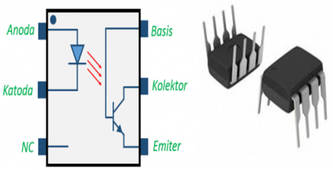
2.4.5 Optocoupler 4n35
An optoisolator, also known as an optoisolator or photocoupler, is an electronic component that transfers an electrical signal between two parts (the source and the receiver) via light. In its application, an optocoupler can be obtained from an IC (Integrated Circuit) such as the 4n35 series IC as shown in Figure 5.
Figure 5. Optocoupler 4n35 [13]
2.4.6 Batteries
Batteries can be interpreted as electric cells that take place electrochemical processes back and forth (reversible) with high-efficiency values. Here there is a process of converting chemical energy into electric power, and vice versa, electric energy into chemical energy [14].
3.1 Design overview
In designing this tool aims to control the input that comes from the merger of the two types of plants called the system of a hybrid between Solar Power Generation and Windmill Power that goes into the battery in the charging process where after the battery is full to avoid overcharging which is then transferred or channeled to the load then regulates the process of using battery power according to the parameters and monitors the value of the amount of electricity in the form of source voltage, voltage and current to the battery. To find out the desired utilization, the next process is to make a schematic circuit through hardware and software, then tested.
3.1.1 Microcontroller ATmega 32
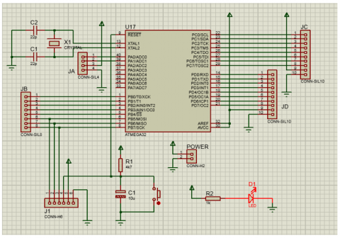
In the controller, tool hybrid is the circuit minimum system needed for microcontroller ATmega 32 can work well [15]. In Figure 6, the following is a series of minimum systems from Atmega 32.
Figure 6. Minimum system for Atmega 32
3.1.2 Designing the PWM charger switching
The design of this PWM charger switching circuit uses an optocoupler component as the input of the PWM channel pin sourced from the ATmega 32 microcontroller, in this case, it is intended that the optocoupler functions as a MOSFET driver that isolates the contact between the PWM voltage coming from the microcontroller and the voltage required as the trigger gate MOSFET in the move or activate the switch on or off. This PWM charger switching circuit uses components such as resistors, optocouplers, diodes, MOSFETs that are connected as shown in Figure 7 below:
Figure 7. PWM Charger switching circuit
3.2 Hybrid controller support device specifications
The hybrid controller that has been made will be used in conjunction with other supporting devices. Where the controller will function to bridge the power supply source with the load. These devices have the following specifications.
3.3 Types of windmills
Figure 8 below a windmill with a total of 6 blades that have been installed and operational. The windmill is made using high-quality PVC material which is strong and durable. The propeller drives the generator to generate electricity, but the process to convert wind into prime mover This wind energy prototype has been installed on the roof of the house. Figure 8 shows a prototype windmill power plant.
Figure 8. The Mini power plant with windmill installed
Table 1 shows the specifications of the windmill with a 3-phase generator at an output voltage of 12 volts, there are 6 blades made fiber. Measuring a minimum wind speed of 2 m/s produces a minimum power of 300 watts, while a maximum wind speed of 15 m/s produces a maximum power of 400 watts.
Table 1. Specifications Windmill
|
Power |
300 |
watts |
|
Maximum Power |
400 |
watts |
|
Wind of Speed Minimum |
2 |
m/s |
|
Wind of Speed Maximum |
15 |
m/s |
|
Wind of Speed Actually |
10 |
m/s |
|
Type Generator Synchronous |
3 Phase Magnetic |
|
|
Casting Generator |
Aluminum Alloy |
|
|
Output Voltage |
12-volt ac |
|
|
Numbers |
6 Blades |
|
|
Material Blades |
Fiber |
|
3.4 Phovoltaic species
The following is a picture of the photovoltaic used. The number of solar panels used is as shown in 2 units with a capacity of 100 Wp each, as shown in Figure 9, with of optimum current 5.68 A of optimum voltage 17.6 volts, specification is shown in Table 2.
Figure 9. Installation of Photovoltaic.
Table 2. Photovoltaic Specification
|
Maximum Power (Wp) |
100 |
Wp |
|
Optimum Voltage (Vmp) |
17.6 |
volt |
|
Optimum Current (Imp) |
5.68 |
A |
|
Open Circuit Voltage (Voc) |
21.09 |
volt |
|
Short Circuit Current (Isc) |
5.08 |
A |
|
Nominal Operating Temperature |
50 |
°C |
|
Operation Temperature |
-40°C to 85°C |
|
|
Maximum System Voltage |
1,000 |
volt dc |
3.5 Battery type
The battery used is a dry cell type which has a voltage of 12 volts dc with a current capacity of 45 Ah, specification is shown in Table 3.
Table 3. Battery specification
|
Battery |
Voltage |
Capacity |
Color |
|
Dry |
12 volt |
45 Ah |
Black |
4.1 Testing tools with autotrafo
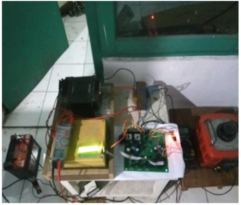
This testing tool is a test of the system tool which aims to determine the performance of the operation of all systems whether or not it is following the specifications of the tool being made. Before it can be applied to the actual power plant hybrid, the first step is to try or simulate this tool first, therefore testing of the tool with an autotrafo is carried out which aims to determine the characteristics and work of the hybrid controller and function as a simulation to replace wind turbine power plant and photovoltaic power plant as a source of voltage input. and the charging current to the battery. Figure 10 below is a simulation of the process of testing the tool controller is a hybrid using autotrafo, transformers CT, with rectifier full wave.
Figure 10. Testing tool controller using autotrafo
4.2 Testing with the windmill
Testing using a windmill was initially carried out by connecting the windmill generator output cable to the controller. The windmill used has three outputs because it uses a 3-phase generator. The 3-phase source is then rectified by the rectifier circuit on the controller. Then use an anemometer tool to find out the value of wind speed as shown in Table 4.
Table 4. Measurement loading on Windmill
|
Time |
Wind of speed |
Voltage |
Current |
Power |
Batt. Voltage |
|
(m/s) |
(V) |
(A) |
(W) |
(V) |
|
|
13:45 |
4.20 |
6.52 |
0.40 |
2.61 |
11.10 |
|
13:47 |
4.50 |
7.56 |
0.52 |
3.93 |
11.10 |
|
13:49 |
4.80 |
7.92 |
0.58 |
4.59 |
11.10 |
|
13:51 |
7.40 |
11.85 |
0.96 |
11.37 |
11.20 |
|
13:53 |
8.50 |
12.48 |
1.24 |
15.47 |
11.20 |
|
13:55 |
6.80 |
11.68 |
0.93 |
10.86 |
11.40 |
|
13:57 |
10.60 |
13.95 |
2.90 |
40.45 |
11.40 |
|
13:59 |
9.10 |
13.01 |
2.50 |
32.52 |
11.50 |
|
14:01 |
8.00 |
12.10 |
1.02 |
12.34 |
11.60 |
|
14:03 |
8.20 |
12.40 |
1.20 |
14.88 |
11.70 |
|
14:05 |
6.40 |
11.24 |
0.91 |
10.22 |
11.70 |
|
14:09 |
5.00 |
8.62 |
0.66 |
5.71 |
11.70 |
|
14:11 |
5.70 |
9.40 |
0.73 |
6.85 |
11.80 |
|
14:13 |
4.80 |
6.45 |
0.38 |
2.45 |
11.80 |
|
14:15 |
3.60 |
5.43 |
0.19 |
1.03 |
11.80 |
|
14:17 |
8.80 |
12.63 |
1.34 |
16.92 |
11.90 |
|
14:19 |
7.90 |
12.51 |
1.28 |
16.01 |
12.00 |
|
14:21 |
6.10 |
10.60 |
0.87 |
9.22 |
12.00 |
|
14:23 |
2.10 |
4.32 |
0.50 |
2.16 |
12.00 |
|
14:25 |
4.80 |
8.04 |
0.90 |
7.24 |
12.00 |
From the data in Table 4 can be known, that the speed of the prevailing winds is unstable and tend to fluctuate. From the data in Table 4 is also known that the higher the speed of the wind that blows, the higher the voltage generated by the thermal power station.
4.3 Testing with photovoltaics
At this stage is to test the battery charging with a source of electrical energy from solar panels for a 12 volt battery. For charging the 12-volt battery, a solar panel is used with an Open Circuit (Voc) voltage of 21.9 volts and a maximum operating voltage (Vmp) of 17.6 volts to 18 volts.
Table 5. Measurement loading on photovoltaic
|
Time |
Charging |
Battery |
|
|
Voltage |
Current |
Voltage |
|
|
(V) |
(A) |
(V) |
|
|
13:45 |
13.10 |
1.60 |
11.40 |
|
13:47 |
13.30 |
1.80 |
11.60 |
|
13:49 |
13.40 |
2.10 |
12.20 |
|
13:51 |
13.40 |
2.10 |
12.20 |
|
13:53 |
13.50 |
2.40 |
12.30 |
|
13:55 |
13.50 |
2.40 |
12.30 |
|
13:57 |
13.60 |
2.60 |
12.30 |
|
13:59 |
13.60 |
2.60 |
12.30 |
|
14:01 |
13.80 |
2.80 |
12.30 |
|
14:03 |
13.80 |
2.80 |
12.30 |
|
14:05 |
13.40 |
2.10 |
12.20 |
|
14:09 |
13.40 |
2.10 |
12.20 |
|
14:11 |
13.30 |
1.80 |
11.60 |
|
14:13 |
13.30 |
1.80 |
11.60 |
|
14:15 |
13.30 |
1.80 |
11.60 |
|
14:17 |
13.20 |
1.70 |
11.70 |
|
14:19 |
13.20 |
1.70 |
11.70 |
|
14:21 |
13.20 |
1.70 |
11.70 |
|
14:23 |
13.10 |
1.60 |
11.40 |
|
14:25 |
13.10 |
1.60 |
11.40 |
In this test, two PVs with a capacity of 100 Wp each were used. The two PVs are connected in parallel so that the voltage generated by the PV is more stable than the nominal battery voltage so that it can charge the battery and does not exceed the battery range. Then, in parallel PV, it must be considered in the connection of cables and joining of PV, where the PV has different specifications or in the sense that the PV specifications must be the same.
From the data from the charging results, it can be seen that the day and brighter the weather, the greater the current for charging the battery [8]. This is because the large charging current is influenced by the bright intensity of the sun, therefore the placement of the solar panels must be precise so that you can get the maximum sunlight intensity and the solar panels must also be wiped or cleaned so that no stains or dust are sticking to get maximum power. From the data from the charging results, it can be seen that the peak current of charging reaches 5.8 A. The higher the sunlight intensity, the greater the voltage and current generated by the PV. This will affect the battery voltage. Table 5 is known that the battery voltage will increase as the voltage and charging current given by the PV increase. When the PV charging voltage and current are still below the battery voltage, the battery voltage condition tends to be flat. This happens because the charging voltage on the PV will charge the battery when the voltage is above the battery voltage so that the charging current can flow to the battery. Therefore, in testing using PV, a series of 2 PVs in parallel so that the resulting voltage is greater than the nominal voltage of the battery and the charging current on the battery can flow and does not exceed the battery range limit.
The test results with monocrystalline PV test with the 100 Wp type used is arranged in parallel so that the PV becomes a capacity of 200 Wp. However, the actual test voltage obtained during peak or sunny weather reaches 14.5 volts and the current is 5.8 Amperes generated at 84.1 watts. The windmill test used obtained an electric power of 40.45 watts. Based on the specifications, the windmill used is capable of producing power up to 300 watts. The average wind speed at the test site is located in urban areas only 2-6 m/s. Meanwhile, based on the specifications of the windmill, it will work optimally at wind speeds from 8-10 m/s.
|
A |
Area of the solar module, m2 |
|
V |
nominal voltage, volt |
|
I |
current, Ampere |
|
P |
dense sun intensity power, Wp |
|
dc |
direct current |
|
Wp |
maximum power, watt peak |
|
Vmp |
optimum voltage, volt |
|
Imp |
optimum current, A |
|
Voc |
open circuit voltage, volt |
|
Isc |
short circuit current, A |
|
η |
Efficiency |
[1] Suryadi, A., Asmoro, P., Solihin, A. (2019). Hybrid electric power plant using wind turbine savonius helix and solar cell as an alternative power source in the lightning tower at flashing lights. ADI Journal on Recent Innovation (AJRI), 1(1): 1-6. https://doi.org/10.34306/ajri.v1i1.3
[2] Suryadi, A. (2020). The implementation of turbine ventilator as an alternative power plant. ADI Journal on Recent Innovation (AJRI), 2(1): 180-185. https://doi.org/10.34306/ajri.v2i1.34
[3] Suryadi, A., Nugroho, E.A., Asmoro, P. (2019). Utilization of speed bump as an alternative energy power plant. Proceedings TEKNOKA, 4: E20-E24. https://doi.org/10.22236/teknoka.v4i0.4168
[4] Suryadi, A., Asmoro, P., Raihan, R. (2019). Utilization of ventilator turbine as alternative power plant. Proceedings TEKNOKA, 4: E15-E19. https://doi.org/10.22236/teknoka.v4i0.4124
[5] Suryadi, A., Ahmad, S., Munthe, B. (2020). Utilization of Savonius hybrid solar cell wind turbines as remote area power plants. Proceedings SNTE, 5(1): 13-17.
[6] Ministry of Energy and Mineral Resources. (2016). Strategic Program for EBTKE and Electricity. Jakarta.
[7] Andrianto, H. (2013). Atmega 16 AVR Microcontroller safe programming using C language (CodeVision AVR), Informatics, Bandung. https://openlibrary.telkomuniversity.ac.id/pustaka/103309/pemrograman-mikrokontroler-avr-atmega16-menggunakan-bahasa-c-codevisionavr-revisi-kedua.html
[8] Yosef, Y. (2018). Control battery charger for solar panels or windmill generators, yogyakarta. Sanata Dharma University. https://repository.usd.ac.id/32494/2/135114046_full.pdf
[9] Koulali, M., Mankour, M., Negadi, K., Mezouar, A. (2019). Energy management of hybrid power system PV wind and battery based three-level converter. Tecnica Italiana-Italian Journal of Engineering Science, 63(2-4): 297-304. https://doi.org/10.18280/ti-ijes.632-426
[10] Boxwell, M. (2017). Solar Electricity Handbook 11 Edition. United Kingdom: Greenstream Brimingham. 11, and 12-13.
[11] Rachman, A., Pratiwi, P., Ashari, L. (2019). Design and performance horizontal axis wind turbine taper type. Jurnal Teknik Mesin (JTM), 9(2): 58-63.
[12] Yang, H., Lu, L., Zhou, W. (2007). A novel optimization sizing model for hybrid solar-wind power generation system. Solar Energy, 81(1): 76-84. http://dx.doi.org/10.1016/j.solener.2006.06.010
[13] Yin, Y., Luo, X., Guo, S., Zhou, Z., Wang, J. (2008). A battery charging control strategy for renewable energy generation systems. In Proceedings of the World Congress on Engineering, pp. 2-4.
[14] Nehrir, M.H., Wang, C., Strunz, K., Aki, H., Ramakumar, R., Bing, J., Miao, Z., Salameh, Z. (2011). A review of hybrid renewable/alternative energy systems for electric power generation: Configurations, control, and applications. IEEE Transactions on Sustainable Energy, 2(4): 392-403. http://dx.doi.org/10.1109/TSTE.2011.2157540
[15] Palaha, F. (2017). Testing prototype home installation using A CS 758 based on arduino. Journal of STT Pekanbaru, 5(2): 67-74. http://dx.doi.org/10.35583/js.v5i2.122