Amina Chenna* | Djamal Aouzellag | Kaci Ghedamsi
© 2020 IIETA. This article is published by IIETA and is licensed under the CC BY 4.0 license (http://creativecommons.org/licenses/by/4.0/).
OPEN ACCESS
The pumped storage hydropower systems are benefits for grid reliability and integration of variable renewable energy, in this context this paper presents the study and control strategy of a pumped storage hydropower (PSH) system based on permanent magnet synchronous machine (PMSM) associated to the renewable energy source. The dynamic behavior of a pump-turbine, including the PMSM with high number of poles, the AC/DC converter and the control of this system, is studied. Also, a control method of the PSH system, which consists of the reversible pump-turbine unit entrained by the PMSM, supplied of the variable power renewable energy source through a power electronic converter. Simulation results obtained on the basis of the dynamic models of the pump-turbine are given, for different operating points, to demonstrate the performance of the proposed system.
pumped-storage hydropower, renewable energy, permanent machine synchronous generator, power control
The increasing penetration of renewable energy sources (RES) in the power system has highlighted the benefits of being able to store energy in a more efficient manner, and the need of holding additional operating reserves to manage the system under more demanding conditions due to the inherent uncertainty and variability of wind and solar power [1, 2].
The increasing penetration of renewable energy sources (RESs) in the power system has highlighted the benefits of being able to store energy in a more efficient manner, and the need of holding additional operating reserves to manage the system under more demanding conditions due to the inherent uncertainty and variability of wind and solar power [1, 3]
A renewed economic and technical interest in energy storage has been observed in recent years because of the increased number of unstable RES. A wide range of energy storage technologies is available today, which provide a large spectrum of performance and capacity for different application purposes [4, 5].
The pumped storage hydropower systems are the most reliable and is the oldest and largest energy storages for accommodating intermittent renewable generators in the power grid [6, 7]. Hydropower is not only environmentally friendly, but also cost-effective [8]. The pumped hydro energy storage (PHES) is a well-established and commercially acceptable technology for utility-scale electricity storage and has been used since as early as the 1890s [9].
Variable speed pump-turbine units have become nowadays-major partner to increase stability of electrical power networks due to their high level of operating flexibility [10, 11]. In addition, pumped-hydro storage facilities can contribute significantly to the load–frequency control in generating mode [12].
Indeed, variable speed pump-turbine units offer several advantages for both pumping and generating modes such as: possibility of active power control in pumping mode, efficiency increase and wide range of operation in generating mode especially under partial load, network stability improvement by reactive power control and network stability improvement by instantaneous active power injection in the network (flywheel effect).
Extended operating range in pump mode and higher efficiency in turbine mode achievable with variable speed units [10, 13].
This paper points out the advantages of the implementation of variable speed pump-turbines use a PMSM and describes the variable speed technology.
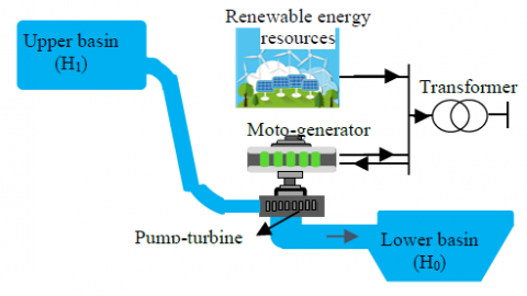
The present work introduced at the pumped-storage hydropower system associated to the renewable energy sources. Which is considered as a promising technology for renewable energy source. A reversible AC pump-turbine unit, based on permanent magnet synchronous machine, is used in the system. The system under study is globally represented by the setup depicted in Figure 1.
Figure 1. A PHES with RES producing electricity
It combined a pumped hydro storage system with renewable energy source. The RES is connected to the grid via two power electronics converters with an intermediate DC link bus where is connected a pumped-storage hydropower system. The modeling details of the scheme studied in Figure 1 are described in detail in further sections.
2.1 Renewable energy source
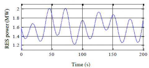
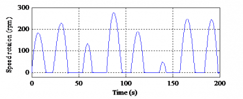
The power profile provided by the RES is given by the Figure 2. In this proposed hybrid system, the electrical grid is mainly supplied by the RES whit fixed power. The excess of energy from the RES is used to pump the water from the lower reservoir to store it in an upper reservoir.
Figure 2. RES power profile
2.2 Mathematical model of PMSM
The PMSM, model in the park reference frame, is described by:
$\left\{\begin{array}{l}v_{d}=R_{s} i_{d}-p \Omega_{w} L_{q} i_{q}+L_{d} \frac{d i_{d}}{d t} \\ v_{q}=R_{s} i_{q}+p \Omega_{w}\left(L_{d} i_{d}+\Phi_{f}\right)+L q \frac{d i_{q}}{d t}\end{array}\right.$ (1)
where, Rs is the stator winding resistance, p is the pair pole number of the synchronous generator, id and iq are, respectively, the direct and quadratic current, Ld and Lq are respectively, the direct and the quadratic inductance respectively, vd and vq are the direct and quadratic voltage and $\Omega_{w}$ is a mechanical speed.
The direct and quadratic magnetic fluxes are given by (the excitation flux Φf is constant):
$\left\{\begin{array}{l}\Phi_{d}=L_{d} i_{d}+\Phi_{f} \\ \Phi q=L_{q} i_{q}\end{array}\right.$ (2)
The electromagnetic torque is also expressed as fellow:
$C_{e m}=p\left(\Phi_{d} i_{q}-\Phi_{q} i_{d}\right)$ (3)
The active and reactive powers are given according to:
$\left\{\begin{array}{l}P=v_{d} i_{d}+v_{q} i_{q} \\ Q=v_{q} i_{d}-v_{d} i_{q}\end{array}\right.$ (4)
2.3 Converter modeling
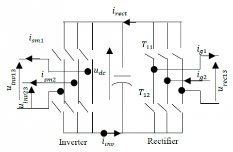
A switching function Tij is defined for each power switch (Figure 3). It represents the ideal commutation and takes the value 1 if the switch is close, 0 when he is open (off):
$T_{i j}=\left\{\begin{array}{l}1 T_{i j} \text { is close } \\ 0 T_{i j} \text { is open }\end{array}\right.$ (5)
$i \in\{1,2,3\}$ number of the arm, $j\in\{1,2\}$ number of the switch in the arm.
Figure 3. Cascade rectifier-inverter
As ideal, power switches are considered, the switches of the same arm are in complimentary states:
$T_{i 1}+T_{i 2}=1 \quad \forall i \in\{1,2,3\}$ (6)
For both three-phase converters, modulation functions can be defined from the switching functions:
$\mathrm{m}=\left[\mathrm{m}_{13} \mathrm{m}_{23}\right]=\left[\begin{array}{ccc}1 & 0 & -1 \\ 0 & 1 & -1\end{array}\right]\left[\begin{array}{c}\mathrm{T}_{11} \\ \mathrm{T}_{21} \\ \mathrm{T}_{31}\end{array}\right]$ (7)
The rectifier leads to the voltages from the capacitor voltage ucap, and the rectifier currents irect, which circulate in the capacitor from the machine current i-sm.
$\left\{\begin{array}{l}\underline{u}_{\text {rect}}=\underline{m}_{\text {rect}} \cdot u_{\text {cap}} \\ i_{\text {rect}}=\underline{m}_{\text {rect}}^{t} \cdot i_{-s m}\end{array}\right.$ (8)
The three-phase inverter modelled in the same way. It yields the inverter voltages $\underline{u}_{i m}=\left[u_{i m 13}, u_{i r v 23}\right]^{T}$ from the capacitor voltage and the inverter currents from the line currents $i_{line}={\left[i_{ line1},i_{line 2}\right]}^{T}$.
$\left\{\begin{array}{l}\underline{u}_{i n v}=\underline{m}_{i m} \cdot u_{c a p} \\ i_{i n v}=\underline{m}_{i m v}^{t} \cdot i_{-i m v}\end{array}\right.$ (9)
2.4 The model of reversible pump turbine
The mathematical model of the pump-turbine describes the relationship between the output mechanical power of the pump-turbine and the guide vane opening. In this paper, the ideal pump-turbine model is used without losses [16, 17]. The transfer function can be written as follows:
$P_{g p}=\frac{1-T_{w} s}{1+0.5 T_{w} s} G$ (10)
where, pgp: The pump-turbine mechanical output power; G: guide vane opening and Tw: The water starting time.
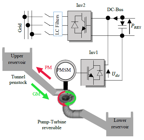
Figure 4. Study system global scheme
The global control scheme of this part is given in Figure 4.
The model of HPS is mainly composed of Pumped storage hydro-plants (a reversible pump turbine model, a PMSM model (520kW), a RES with a maximum power of 2MW. and control system model of the converter. The reversible pump turbine provides mechanical torque for PMSM. The associated control structure is based on the Park model of the PMSM (d, q reference frame) the field-oriented control is used to control of the generator.
3.1 Generating mode
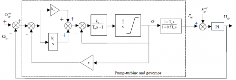
In generating mode, the strategy is presented in Figure 5 consist of a PI type regulator whose output acts on the guide vane opening through a servomotor. The power set point is imposed by the grid conditions and the speed set point is calculated by a speed optimizer in order to maximize the turbine efficiency. This speed optimizer is a look-up table defined as a surface representing the optimal speed as a function of the power and the mass flow rate Qv.
The transfer function of the PI regulator is given by:
$G_{P I}(s)=\frac{1}{z} \cdot \frac{1+\frac{K_{c}}{K_{i}} s}{1+\frac{1}{K_{i}}\left(\frac{1}{z}+K_{c}\right) s}$ (11)
where, Kc: proportional gain, Ki: integral gain, z: the droop, Kp: the gain of the pilot valve and Tp: the time constant of the pilot valve (s).
The strategy in pumping mode consists of a generator power controller similar to the one developed for the strategy in generating mode and of a guide vane opening optimization [15].
Figure 5. Structure of the servomechanism and PI controller
3.2 Control strategy for the PSH system
Exceeded energy, when available, is stored as potential energy in the pumped-hydro storage system by pumping water from a lower altitude to a higher altitude. When the production is not sufficient, this energy is reconverted into the electrical form and transmitted to the DC bus and allows regulating electrical power delivered into the grid. The fundamental control diagram is given in Figure 6.
When the PRES is less than the $P_{g}^{r e f}$ generation mode work. The PHES will convert its present operation mode immediately, and then adjust the speed of the reversible pump-turbine to the maximum in order to reduce the large fluctuation.
When the PRES is higher than the $P_{g}^{r e f}$ pumping mode work. The PHES will adjust the speed of the reversible pump-turbine, meantime modifying the scheduled pumping capacity in this hour period.
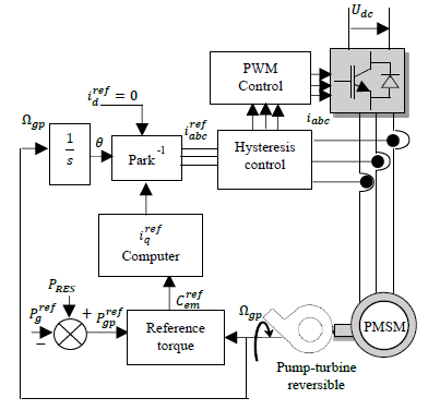
The control structure of the PMSM is based on the Park model (d, q frame) and the field orientation is achieved by regulating the direct current component $i_{d}^{\text {ref }}$ to zero.
The reference value $P_{g p}^{r e f}$ of the active power of the pumped-hydro storage system is determined by:
$\left\{\begin{array}{l}P_{g p}^{r e f}=P_{R E S}-P_{g}^{r e f} \\ P_{g p}^{r e f}=\eta_{g p} \cdot P_{g p}\end{array}\right.$ (12)
Figure 6. Control of the HPS study
Figure 7. Control bloc diagram of the hydroelectric plant
If the PRES is less than the $P_{g}^{r e f}$ generation mode work. The PHES will convert its present operation mode immediately, and then adjust the speed of the reversible pump-turbine to the maximum in order to reduce the large fluctuation. Else if, the PRES is higher than the $P_{g}^{r e f}$ pumping mode work. The PHES will adjust the speed of the reversible pump-turbine, meantime modifying the scheduled pumping capacity in this hour period.
The control structure of the PMSM is based on the Park model (d, q frame) and the field orientation is achieved by regulating the direct current component $i_{d}^{\text {ref }}$ to zero.
The reference value $P_{gp}^{r e f}$ of the active power of the pumped-hydro storage system is determined by:
$\left\{\begin{array}{l}P_{g p}^{r e f}=P_{R E S}-P_{g}^{r e f} \\ P_{g p}^{r e f}=\eta_{g p} \cdot P_{g p}\end{array}\right.$ (13)
where, $P_{gp}^{r e f}$ being the reference grid active power, fixed to the value 1.6 MW, PRES the optimal aerodynamic power generated, and hgp the power hydroelectric plants efficiency. The machine-side converter allows the control of the speed of rotation of the group in the two operating modes (turbine mode and pump mode); whereas the converter on the network side transfers, the power produced to the grid in the turbines mode and supplies the DC-Bus for motor operation in pumping mode. The overall scheme of the control of the micro-hydropower is shown in Figure 7.
3.3 PMSM currents regulation
PMSM currents are regulated by hysteresis controllers, which allow keeping the current wave into range defined around the reference value. When current wave reached the band limits, the hysteresis controller generates a logic signal (0 or 1) (Figure 8). So, for (j=1, 2, 3).
We have:
$\left\{\begin{array}{ll}F_{j}=1 & \text { if } \quad i_{m j}^{\text {ref }}-i_{m j} \geq \Delta i \\ F_{j}=1 & \text { if } i_{m j}^{\text {ref }}-i_{m j}<\Delta i\end{array}\right.$ (14)
With ∆i is the hysteresis band defined in the controller.
Figure 8. Plant Hysteresis regulation principal
3.4 DC-bus regulation
The electrical equations for the circuit are given by:
$\frac{d U_{d c}}{d t}=\frac{1}{c_{d c}} I_{c}$ (15)
With:
$I_{c}=I_{d c}-I_{o n d}$ (16)
The direct inversion of equation (15) makes it possible to obtain the reference current upstream of the inverter. $I_{\text {ond}}^{\text {ref}}$ which is expressed as follows:
$I_{\text {ond}}^{\text {ref}}=I_{d c}-P I(s)\left(U_{d c}^{\text {ref}}-U_{d c}\right)$ (17)
where, PI(s) is the transfer function of the PI regulator and $U_{d c}^{*}$ is the reference of the DC voltage. The transfer function between the $I_{\text {ond}}^{\text {ref}}$ and Idc currents is considered of the first order with a very high dynamic for the synthesis of the corrector; because the dynamics of the current is generally faster than that of the voltage.
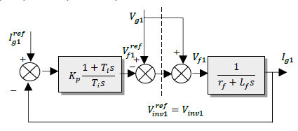
3.5 Grid currents regulation
The reference reactive power is imposed at zero, in order to operate at a factor of unitary power of the grid side. The Figure 9 represented the control of grid side converter, has for objective to obtain current and voltage with acceptable wave form and to ensure unitary power factor.
The electrical equations downstream the converter can be expressed as follows:
$\left\{\begin{array}{l}I_{g 1}=\frac{1}{r_{f}+L_{f} s}\left(V_{i n v 1}+V_{g 1}\right) \\ I_{g 2}=\frac{1}{r_{f}+L_{f} s}\left(V_{i n v 2}+V_{g 2}\right)\end{array}\right.$ (18)
The use of mathematical model of converter (with assumption of an equilibrate voltage system) allows expressing simple voltages reference as follows [18, 19]:
$\left(\begin{array}{c}V_{i n v 1}^{r e f} \\ V_{i n v 2}^{r e f} \\ \end{array}\right)=\left(\begin{array}{c}V_{f 2}^{r e f} \\ V_{f 2}^{r e f}\end{array}\right)+\left(\begin{array}{c}V_{g 1} \\ V_{g 2}\end{array}\right)$ (19)
With PI regulation of grid currents, we obtained the reference voltages $v_{f 1}^{r e f}$ and $v_{f 2}^{r e f}$ (Figure9) [16, 17]:
$\left(\begin{array}{c}V_{f 1}^{r e f} \\ V_{f 2}^{r e f}\end{array}\right)=P I(s)\left(\begin{array}{cc}I_{g 1}^{r e f} & I_{g 1} \\ I_{g 2}^{r e f} & I_{g 2}\end{array}\right)$ (20)
Figure 9. Grid current regulation
Tables 1-4 give the parameters for the reversible pump-turbine, the PMSM and the electrical grid. The studied system, shown in Figure 7, is implemented in the Matlab\Simulink software environment. The results of simulation are obtained for active power reference $p_{g}^{\text {ref}}=1.6 M W$, the reactive power reference $Q_{g}^{\text {ref }}=0$ and the typical RES power given in Figure 2.
Table 1. Basic parameters of Pump turbine hydropower
|
Designation |
Value |
|
nominal power |
520 kW |
|
Rate speed |
360 rpm |
|
Efficiency |
0.76 |
|
Designation |
Value |
|
Frequency |
50 Hz |
|
Stator winding resistance |
12 mΩ |
|
Direct cyclic inductance |
0.13 mH |
|
Quadratic cyclic inductance |
0.13 mH |
|
Excitation Flux |
2.5Wb |
Table 3. Basic parameters DC-Bus, Filter and grid
|
Designation |
Value |
|
DC-Bus voltage |
1.5 kV |
|
DC-Bus capacitor |
0.015 F |
|
Inductance filter |
0.002 H |
|
Resistor filter |
0.01Ω |
|
Grid voltage (Rms) |
690 V |
Table 4. Value of the feedback gains PI
|
Designation |
Value |
|
Proportional gain |
2.15 |
|
Integral gain |
0.43 |
Figures (10-12) show the speed rotation, the guide vane opening and the power in generating mode.
The guide vane opening increases along with the increase of power, there is a small fluctuation, which is caused by the power fluctuation.
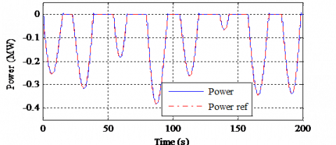
The pumped-storage hydropower power follows the variation in according to the active power transmitted to the DC-bus as results, reversible pump-turbine speed slowdown or accelerate in order to return or store energy, respectively.
Figure 10. Speed rotation in generation mode
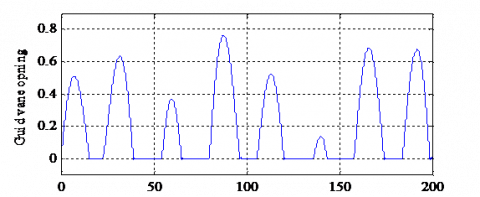
Figure 11. Guide vane opening in generating mode
Figure 12. Power in generating mode
Figure 13. Speed rotation in generation mode
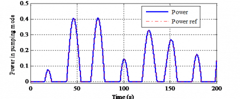
The speed rotation, the guide vane opening and the power in pumping mode are given by the Figures (13-15).
Figure 14. Guide vane opening in generating mode
Figure 15. Power in pumping mode
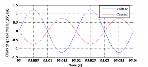
Figure 16. Grid voltage and current
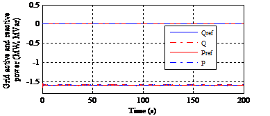
Figure 17. Grid active and reactive powers
Figure 18. Grid power coefficient
The guide vane opening increases along with the increase of power. The Pumped-Storage power follow the variation in according to the active power transmitted to the DC bus as results.
The results of simulation for both modes evidence the performance of the variable speed hydropower plant, showing a dynamic response excellence when the system switches from the generate mode ($\Omega_{g p}>0$) to the pumping mode ($\Omega_{g p}<0$). Ensure the stability of the speed control, when the reversible pump-turbine units operating state changes, in order to avoid emitted active power fluctuations of the RES. The power variation for both modes follows the variation of the guide vane opening, that assuring more efficient management of available RES.
The response is almost instantaneous compared to the conventional fixed speed reversal mode where the response time can exceed a few minutes (due to the complex reversal procedure).
Figure 16 gives the grid voltage and current with sinusoidal wave form at constant frequency, the use of hydroelectric allowed providing a regular and smooth active power to the electrical grid and compensates fluctuations in Renewable Energy Source by controlling the voltage and the frequency (50Hz) of the electrical network.
Figure 17 shows the active and reactive powers, the grid active power remains constant at 1.6 MW and the grid reactive power is equal to zero, which corresponds to unitary power factor in Figure 18.
The pumped storage hydropower associated to the renewable energy source has been studied in this paper. The first part is devoted to the analysis, modeling and simulation of each part of the system. In the second part, the PHES schema including a PMSM using a reversible pump-turbine unit is detailed. A dynamic response and governor tuning of pumped hydroelectric energy storage has been developed and studied.
The simulation results have confirmed the reversible pump-turbine operation in that variable speed technology allows for rapid transition between the two operating modes. This advantage of the pumped hydroelectric energy storage system offers a high performance for the compensation of the power fluctuation of renewable energy sources.
The variable speed technology in pump-turbines permits the energy storage and production with a fast reactivity (seconds), the grid frequency regulation (in both regimes pump and turbine) and the optimization of the efficiency of the hydraulic power plants.
The variable speed technology in pump-turbines is a breakthrough technology that starts to be implemented, due to the new energy market configuration.
We would like to thank the Directorate general for scientific research and technological development for funding our Laboratory.
|
PSH |
Pumped storage hydropower |
|
PMSM HPS |
permanent magnet synchronous machine Hybrid power system |
|
RES |
Renewable Energy Source |
|
AC/DC |
Converters |
|
PV |
Photovoltaic energy |
|
Pgp |
power of pump-turbine unit |
|
$P_{g p}^{r e f}$ |
Reference power of the pump-turbine |
|
PRES |
Power of the RES |
|
Pdc |
Power of DC-voltage |
|
$P_{d c}^{r e f}$ |
Reference power of the CD voltage |
|
$Q_{g}^{r e f}$ |
Reference power of the grid |
|
Q |
grid reactive power |
|
P |
grid active power |
|
Pref |
grid active reference power |
|
Cem |
Electromagnetic torque |
|
vd |
Direct voltage |
|
vq |
Quadratic voltage |
|
$Q_{g}^{r e f}$ |
Reference power of the grid |
|
Q |
grid reactive power |
|
id |
Direct current |
|
iq |
Quadratic current |
|
Rs |
stator winding resistance |
|
Lf |
Inductance filter |
|
Rf |
Resistor filter |
|
H1 |
Upper level |
|
H0 |
Lower level |
|
Tij |
witching function |
|
G |
Guide vane opening |
|
Tw |
Water starting time |
|
Udc |
DC voltage |
|
id |
Direct current |
|
Kc |
Proportional gain |
|
Ki |
Integral gain |
|
Kp |
Proportional gain of pilot valve |
|
z |
Droop coefficient |
|
Ig1 |
Grid current |
|
Ig2 |
Grid current |
|
Vg1 |
Grid voltage |
|
Vg2 |
Grid voltage |
|
Greek symbols |
|
|
ηgp Φf Φd Φf $\Omega_{g p}^{r e f}$ Ωgp Ωw |
Efficiency of the pump-turbine unit Excitation flux Direct magnetic fluxes Quadratic magnetic fluxes Mechanical speed reference of the pump-turbine unit Mechanical speed of the pump-turbine unit mechanical speed of the PMSM |
[1] Kougias, I., Aggidis, G., Avellan, F., Denis, S., Lundin, U., Moro, A., Muntean, S., Novara, D., Pérez-Diaz, J.I., Quaranta., E., Schil., P., Theodossion, N. (2019). Analysis of emerging technologies in the hydropower sector. Renewable and Sustainable Energy Reviews, 113. https://doi.org/10.1016/j.rser.2019.109257
[2] Pérez-Diaz, J.I., Chazarra, M., Garcia-Gonzalez, J., Cavazzini, G., Stoppato, A. (2015). Trends and challenges in the operation of pumped-storage hydropower plants. Renewable and Sustainable Energy Reviews, 44. http://dx.doi.org/10.1016/j.rser.2015.01.029
[3] Gajic, A., Stevanovic, V., Pejovic, S., Karney, B. (2019). Hydro storage reduces electricity costs and keep wind and solar unpolluted. 29th IAHR Symposium on Hydraulic Machinery and Systems. IOP Conf. Series: Earth and Environmental Science, 240: 082015. http://dx.doi.org/10.1088/1755-1315/240/8/082015
[4] CEER. (2018). Status Review of Renewable Support Schemes in Europe for 2016 and 2017. Public report, Ref: C18-SD-63-03, Council of European Energy Regulators asbl.
[5] Trainer, T. (2019). Some questions concerning the Blakers et al. case that pumped hydro storage can enable 100% electricity supply. Energy Policy, 128: 470–475. https://doi.org/10.1016/j.enpol.2018.12.063
[6] Rozali, N.E.M., Alwi, S.R.W., Manan, Z.A., Klemeš, J.J., Hassan, M.Y.(2013). Optimisation of pumped-hydro storage system for hybrid power system using power pinch analysis. Chemical Engineering Transactions, 35: 85-90. https://doi.org/10.3303/CET1335014
[7] Anagnostopoulos, J.S., Papantonis, D.E. (2007). Simulation and size optimization of a pumped–storage power plant for the recovery of wind-farms rejected energy. Renewable Energy, 33: 1685–1694. https://doi.org/10.1016/j.renene.2007.08.001
[8] Siemens Company. (2017). Pumped storage machines Reversible pump turbines, Ternary sets and Motor-generators. https://voith.com/corp-en/11_06_Broschuere-Pumped-storage_einzeln.pdf
[9] Rehman, S., Al-Hadhrami, L.M., Alam, M. (2015). Pumped hydro energy storage system: A technological review. Renewable and Sustainable Energy Reviews, 44: 586-598. http://dx.doi.org/10.1016/j.rser.2014.12.040
[10] Kuwabara, T., Shibuya, A., Furuta, H., Kita, E., Mitsuhashi, K. (1996). Design and dynamic response characteristics of 400 MW adjustable speed pumped storage unit for Ohkawachi Power Station. IEEE Transactions on Energy Conversion 1996, 11(2): 376-384.
[11] Pannatier, Y., Nicolet, C., Kawkabani, B., Deniau, J.L., Schwery, A., Avellan, F., Simond, J.J. (2008). Transient behavior of variable speed pump-turbine units. 24th Symposium on Hydraulic Machinery and Systems ResearchGate 2008, pp. 1-14.
[12] Sarasúa, J.I., Pérez-Díaz, J.I., Wilhelmi, J.R., Sánchez-Fernández, J.A. (2015). Dynamic response and governor tuning of a long penstock pumped-storage hydropower plant equipped with a pump-turbine and a doubly fed induction generator. Energy Conversion and Management Journal, 106: 151–164. https://doi.org/10.3390/en81011430
[13] Zhang, G.P., Zhao, Q., Ren, J.Y., Song, X.F., Han, M.X. (2017). Modelling and control of doubly fedvariable-speed pumped storage units for grid power regulation. The 6th International Conference on renewable Power Generation, pp. S745–S750. https://doi.org/10.1049/joe.2017.0430
[14] Zhang, S., Tseng, K.J., Vilathgamuwa, D.M., Trong, D.N., Wang, X.Y. (2011). Design of a robust grid interface system for PMSG-based wind turbine generators. IEEE Transactions on Industrial Electronics January, 58(1): 316-328. https://doi.org/10.1109/TIE.2010.2044737
[15] Allard, B., Costa, F., Labouré, É.L., Lubin, T., Mazaleyrat, F. (2002). Machines électriques tournantes : Conception, construction et commande. Techniques de l’Ingénieur 2002, réf: TI301- Conversion de l’énergie électrique.
[16] Belhadji, L. (2013). Optimisation du contrôle commande d’un système hydraulique réversible à vitesse variable. Thèse doctorat, Ecole Doctorale Electronique, Electrotechnique, Automatique & Traitement du signal, Laboratoire de Génie Electrique de Grenoble 8 juillet 2013.
[17] Nguyen Ngoc, P.D. (2011). Optimisation de systèmes de production intermittents et non conventionnels couplés au réseau électrique. Thèse de doctorat, université de GRENOBLE, Laboratoire G2ELAB, l'École Doctorale EEATS, France.
[18] Hamrouni, N., Jraidi, M., cherif, A. (2008). New control strategy for 2-stage grid-connected photovoltaic system. Renewable Energy, 33: 2212-2221. https://doi.org/10.1016/j.renene.2007.12.021
[19] Xu, P., Shi, K., Zhao, D., Liu, R., Zhu, Y. (2016). Modeling and simulation of grid-connected inverter based on outloop power control and experimental verification. AMSE Journals, 89(1): 143-155.