Arief Goeritno*![]() | Yhudha Prasetiya
| Yhudha Prasetiya![]() | Yuhefizar Yuhefizar
| Yuhefizar Yuhefizar![]() | Muhathir Muhathir
| Muhathir Muhathir![]() | Selamat Lestari
| Selamat Lestari![]() | Irham Muhammad Azama
| Irham Muhammad Azama![]()
© 2023 IIETA. This article is published by IIETA and is licensed under the CC BY 4.0 license (http://creativecommons.org/licenses/by/4.0/).
OPEN ACCESS
To increase the efficiency of the time used when measuring the voltage value on the battery system and each battery cell, it is necessary to maintain the condition of the battery so that it can work optimally through the build and installation of an embedded system prototype based on the Internet of Things (IoT) platform for preventing the failure on the battery system at the Substation of Kedungbadak-Bogor in a real-time condition. There are two subjects in this article are related to the research objectives, namely i) device manufacturing and programming and ii) device prototype performance measurement. The research implementation algorithm as a form of the research method was chosen. The formation of the subsystem is carried out through integrated wiring between electronic devices, in order to obtain the hardware handshaking process and conditions, whereas the subsystem programming is done through making algorithms and compiling syntax, in order to obtain handshaking by software. The performance of the subsystem is measurable when integrated into the smartphone via the Blynk IoT application, in order to obtain hardware and software handshaking processes. The performance of the device prototype when monitoring the voltage in the form of information about the measured voltage value of each battery cell, namely the voltage value displayed on the ‘client system’, ‘server system’, and ‘smart-phone’, while the battery cell voltage drop alarm is in the form of notifications on smart-phones and emails containing notifications voltage drop in one of the battery cells. Fabricating the embedded device prototype can provide measurement efficiency and early detection of anomalies in battery cells.
prototyping an embedded device, IoT-platform, prevent the failure on the battery system, Kedungbadak-Bogor substation
This research is supported by the idea that there is a lot to do with the Internet of Things (IoT) when it is used for the operation of Embedded Devices (EDs) [1, 2], such as connectivity, analytics, integration, active engagement, and many more. The IoT is the relationship between physical devices and applications with the provision of facilities for access and control of the device [3]. The main goal of IoT is to remotely access and operate devices with little or no human assistance [2]. Besides being supported by thoughts, this research is a number of activities related to the concept of how to measure the value of the voltage on an object that has electricity, especially the battery voltage system [4]. The concept of how to measure is only in the appointment of values. It can also be marked with an alarm through the sound of a buzzer when there is a decrease or increase in the voltage value of an electrified anything, so it is a form of limitation. Upgrading the concept of how to measure the battery voltage is an effort to ease monitoring of the overall voltage value for the battery system at the substation of the electrical apparatus. The device, as well as to increase the efficiency of the time used when the activity for measurement of the voltage value on the battery system and each battery cell [5]. The success of making this overall monitoring and measuring device is an effort to guard the battery conditions so that it can perform optimally [6]. Based on the description of the background, the title of this article is associated with IoT-based an embedded device prototype to measure the battery voltage in real-time at the Kedungbadak-Bogor Substation.
Several state-of-the-art studies serve as a guide in this article which include (i) an embedded device prototype based on the IoT, (ii) measuring the battery voltage in real-time, and (iii) the Substation of Kedungbadak-Bogor. Integrated equipment in IoT can communicate through the internet network to share and transfer information with unique identities set for each device, such as Unique Identification (UID) [7]. Data from physical devices is sent via the internet network so that it can be displayed on the application [8]. The relationship between devices and IoT aims to achieve integrated device performance, safe and fast in real-time, and with personal service ownership, such as long-distance monitoring, measurement, search, scheduling, recording, recording, maintenance, and reporting [9]. The integration process between the system and the internet network is used by the Wi-Fi module, so that data is received by a microprocessor and sent to the web server so that the data can be accessed in a network or online [10]. The location of various objects on the internet network has created very significant changes in the field of an economy based on Information and Communication Technology (ICT) [11]. A large number of sensors connected to the internet network become a problem for IoT task management, data process, and decision-making system because it must be given the same service to users, so latency needs to be anticipated in the management and processing of data from the sensor installed on IoT [1, 2]. Certainty of the best Quality-of-Service (QoS) with low latency resolution for IoT applications, IT services, user tasks, and client events in the ecosystem is very important for the support of real-time applications that are aware of latency [1, 2, 12]. Proper care and precautions can be taken by implementing an IoT [11].
Monitoring and measurement of battery system voltage in the substation environment in general [13], as well as in the Substation of “Kedungbadak-Bogor” which is carried out periodically is sustainable [14]. Measurement of the overall battery system voltage value is done every day, while each battery cell is done every week [15]. Guided by the role and function of the battery system in each substation, a prototype-shaped system is assisted by a microcontroller (μC) or microcontroller unit (MCU) [16] through real-time mechanisms based on the IoT [17]. The prototype is used as an integrated electronic device for monitoring and gauge of the system voltage and battery cell values in the Substation of "Kedungbadak-Bogor" so that the voltage value can be displayed on the smartphone in real-time condition.
Research on Real-time Monitoring Systems (RMS) on electric devices has been carried out in recent years. Devices that are the object of research and parameters of measurable electrical power in each previous study vary greatly [9]. Real-time Monitoring System is widely used in tools with sensitive tendencies to changes in value in the termination data, such as Early Warning Systems (EWS) [18] for disasters, anomaly warnings in a tool, detection of value change wind speed on a windmill, or other forms [19]. The parameters of environmental conditions are not in accordance with the criteria and can be recognized by the system as a form of disturbance. The disturbance of the system was responded to by sending a message of disturbance warning or the system was deactivation for more severe damage to prevent damage [20]. Data obtained can be expected to be as accurate as possible for further data processing, such as for database purposes (databases) or data evaluation needs [21]. Real-time monitoring systems are built through the use of web-based client-server communication on networks on the public internet, or reserve proxy. The quality of data communication on the client side is influenced by the network conditions of the Internet Service Provider (ISP) used. This is evidenced by the results of measuring the quality of data transmission that changes every time [22]. The RMS capability can be made a resource server in real-time from remote areas [23].
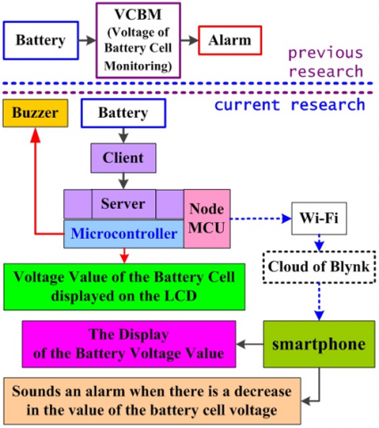
Based on the essence of the results of the general research according to a number of previous research results in the use of μC-based electronic devices [16] both the microcontroller module is the custom design [24-30] or direct use of the Arduino board [31-41] which was integrated into the mini-motherboard system of being raised for a number of purposes [24, 25, 27-33, 36-41]. This study was also motivated by previous research related to the use of internet networks [34-37, 39, 40]. Guided by previous research that is similar and closely related, a prototype of monitoring and voltage gauge of the system and battery cells in the Substation of Kedungbadak-Bogor in real-time through the IoT-based system. The design concept is based on the concept of how to measure the voltage value on something that is voltage [14] with an increase in the monitoring and measurement of the IoT-based voltage value. The microcontroller is installed on two different kinds of devices, namely the client and server systems. The voltage value of each battery cell is read by the client as data sent to the server, after the data from each client is successfully collected, then the server sends the information to the Internet network (server from Blynk IoT) [42] and the download process is carried out with the Blynk IoT application on the smartphone for the appearance of the value data of the voltage of each battery cell in real-time. A schematic diagram of the formulation of the problem for the design of an IoT-based embedded system prototype is shown in Figure 1.
Figure 1. A schematic diagram of the formulation of the problem for the design of an IoT-based embedded system prototype
Referring to Figure 1, it can be explained, that the previous research was only in the form of an alarm sound when the battery cell voltage was less than the standard value, while the current research is a very extraordinary development of previous research. The embedded device prototype is an integrated electronic device consisting of client and server systems. The board of Arduino-NANO is used as a control center for a client system and the board of Arduino-ProMEGA2560-R3 is used as a control center for a server system, as similar things when a personal computer (PC) is used for other utilization [43]. Planting the syntax structure of Arduino IDE-based program ideas into the memory of the microcontroller is guided by previous research articles [24, 28, 31-41]. The performance of the system prototype in real-time based on IoT is actualized to observe the voltage value of each battery cell that is sent and displayed on the smartphone screen, while the appointment of the alarm condition when there is a decrease in the voltage value of each battery cell.
According to the previous paragraphs of the background, state-of-the-art, and problem formulation, then the research objectives are set, namely (a) designing, fabricating, assembling, and wiring integrated the Arduino board-based embedded device prototype and (b) measuring the performance of the embedded system based on a microcontroller and the IoT when monitoring and measuring the voltage values of the battery system and cell in the real-time condition. In this article, firstly, after achieving the first research objective, it is hoped that the purposes will be obtained a physical form of an embedded device prototype through the procedures, namely manufacturing the mini-motherboard, wiring integrated into the client and server systems, and programming for microcontrollers and smart-phones. Secondly, when the second research objective has been obtained, it can be expected to exist the performance of the embedded device prototype through the procedures, namely measuring the voltage rating of each battery cell and response to the setting for alarm conditions when there is a decrease in the value of the battery cell voltage. The rest of this article is organized like the pattern in the previous article [44] with sorting as follows, namely, chapter 2 presents literature review, chapter 3 presents our proposed methods of the research, chapter 4 presents the results and discussion based on the two research objectives, and chapter 5 presents the determination of conclusions.
This Literature Review chapter is a brief explanation related to previous studies that are used as guidelines in conducting current research. This chapter consists of several sections, starting with a section with an overview description of the comparison between embedded devices and IoT [1, 2]. The next part is an explanation of a number of previous studies regarding the role of embedded devices for several uses and these embedded devices are not connected to the Internet network. The final section is an explanation of previous research on embedded devices linked to the Internet network for the operating mechanism, namely the system based on RemoteXY version 4.5.1 [45, 37] to display the operating process on Android smartphones and operating systems based on cloud-based multiplatform instant messaging applications, e.g., Telegram [40].
Embedded Systems (ES) or more specifically in the form of Embedded Devices (EDs) and the Internet of Things (IoT) are both computer-controlled systems, so the two must also meet the appropriate criteria [46]. Embedded devices, may not be linked to the Internet or always linked to the Internet, therefore the existence of embedded devices tends to be ubiquitous among all electronic devices. Embedded devices are part of a specific system, while an IoT system is linked to the Internet and interacts with other devices. An embedded device is based on a system of microprocessors or microcontrollers which is designed to perform a specific task, while an IoT concept implies the creation of a distributed network consisting of numerous physical objects equipped with a centralized platform via the Internet. In many other ways, embedded devices linked to the Internet system are commonly found in consumer, home appliances, automotive, medical, telecommunication, commercial, industrial, aerospace, and military applications [1, 2].
A number of studies that have been carried out related to embedded devices, but not linked to the Internet, include (i) temperature conditioning in a room analogy with the help of temperature sensors [33], (ii) control of incandescent lamps in three-phase electrical system networks [43], (iii) early detection of drinking water quality with the help of contacting-conductivity sensors [24], (iv) monitoring of battery voltage on buses [27], (v) analogy control of smart greenhouses [30], (vi) a segmented load control system on a three-phase power network assisted by voltage and current sensors [31], (vii) a control system assisted by a fingerprint sensor integrated into the engine immobilizer [29], (viii) a locking system assisted by an RFID sensor [28], (ix) telephony and radio-frequency based telecommunication system interface with half-duplex mechanism assisted by dual-tone multiple-frequency buttons [32], (x) a system with battery back-up for incubator operation [36], (xi) a system for converting the amount of plastic waste into monetary value using RFID sensors and load cells [38]. These studies are in the Indonesian language and have been published in a number of journals accredited by the government of the Republic of Indonesia or as part of a number of national seminar proceedings. Based on these explanations, this research is a form of implementing the use of a number of sensors as electronic devices connected to the input lines of the microcontroller, the microcontroller itself, and a number of actuators with interfaces connected to the output lines of the microcontroller [24, 25, 27-41].
Several studies related to the utilization of the embedded system concept which is manifested in the form of an embedded device with an operating mechanism via the Internet network and controlled via a smart-phone. Embedded devices with the RemoteXY application-based operating system [45, 37] have two main explanations. First, integration of hardware and software for embedded system requirements through the existence of a hardware and software system block diagram consisting of three blocks, i.e., input, process, and output. Second, based on the availability of the embedded system as a whole, a validation test can be carried out with 3 observation states when "opening", "closing", and there is a lock/unlock that is observed directly and in real-time related to the functionalization and performance of the web-based control unit [37]. Research on the development of previous research was carried out through changes to the operating system, from the RemoteXY application to the Telegram application [40]. The performance of the embedded system with a Telegram-based operating system obtained performance results through a validation test process which was observed through the stages of starting operation and the activation process, followed by the "closing the gate" operating process, the "closing the gate" operating process, and performance comparison with previously manufactured devices. Based on the explanations of these two things, the current research position is in the form of making embedded devices connected to the Internet network with the help of one of the Internet-platforms, e.g., Blynk [42]. Based on the explanations of these two things, the current research position is in the form of making embedded devices connected to the Internet network with the help of one of the IoT platforms.
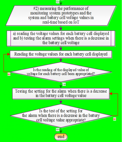
The research methods are unity an algorithm of a researcher for conducting the research that is carried out in the form of stages to achievement and which is guided by the research objectives as shown in some previous articles [47, 48]. In other words, some stages must be carried out sequentially the objectives [18, 34, 35, 47-50], so this research method is made in the form of a flow chart, and under steps for achieving each research objective [18, 34, 35, 47-50]. A number of materials and tools are needed in this study as support for each process in the research method, in order to obtain research objectives through problem limitation. The research material is in the form of a number of modules for the achievement of a device prototype for a real-time IoT-based battery voltage monitoring system. Software requirements for research include the direct use of the Arduino IDE and the Blynk IoT application used in previous research articles [42].
Figure 2. The flowchart of the research methods
The research method, which is based on previous research, is an algorithm for conducting research in the form of several stages that are useful for achieving each research objective. The research method is in the form of a flowchart, as shown in previous research articles [32, 47-50]. The flowchart of the research methods is shown in Figure 2.
Based on Figure 2, it can be explained, that the research methods contain two research objectives, namely -designing a monitoring system prototype and -measuring the performance of a monitoring system prototype when used for monitoring and measuring system voltage values and battery cells in real-time based on IoT.
This research article conveys two main things as research objectives. Regarding the first objective, after designing a prototype, it is followed up by making a number of electronic circuits and modules. Furthermore, integrated wiring is carried out for all electronic circuits and modules through each pin on the corresponding ports. The achievement of the integrated form of wiring is the success of the hardware handshaking. With an integrated system prototype, an operating program structure is created for the Arduino board and smart-phone device, so that each part of the system prototype can communicate with other. Achieving the condition of being able to communicate with each other is the success of software handshaking. Explanation of each step in the sequence of procedures for achieving each research objective, then described in the following two sub-chapters.
3.1 An embedded device prototype design
Designing an IoT-based embedded device prototype for monitoring the battery voltage in real-time was carried out by (i) manufacturing a mini-motherboard and wiring integrated for the client-server systems and (ii) programming into Arduino boards based on an Arduino IDE and into a smartphone with the help of the Blynk IoT application.
3.2 Performance measurement into system prototype
The steps needed to measure the performance of the monitoring system and measure the voltage value of the IoT-based system and battery cells are carried out based on (i) the displayed voltage reading for each battery cell and (ii) testing the settings for the alarm when there is a decrease in the battery cell voltage value.
4.1 The physical form of an embedded device prototype
The design for the establishment of a system prototype in the form of a set of electronic instruments assisted by an Arduino board to monitor and measure the voltage value of the battery system and cells in real-time based on IoT has been carried out in stages (i) making a mini-motherboard and wiring the client and server systems and (ii) embedding the program syntax structure onto Arduino board based on Arduino IDE and onto smartphones based on the Blynk IoT application.
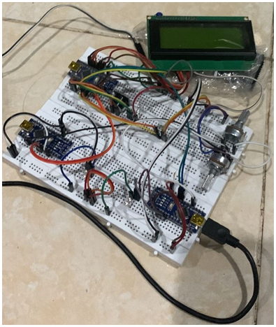
4.1.1 Manufacturing the mini-motherboard and wiring integrated to the client and server systems
Manufacture of mini-motherboards in the form of a single layer printed circuit board (PCB) as an integration center in wiring for monitoring the system prototype and as a liaison for various electronic components and modules as has been implemented in the methods and processes in previous studies. The physical of mini-motherboard for client system is made separately from the mini-motherboard for server system. The schematic diagram for wiring integration of the client and server system is shown in Figure 3.
Based on Figure 3, it can be explained that (i) the assembly of the server system as a data collection center from several client systems is to be sent to the Blynk IoT cloud server. Arduino Pro MEGA2560 R3 is used as the main controller for the server system, (ii) the installed LCD functions to display cumulative battery cell voltage measurement data from several client systems, (iii) the buzzer is installed to warn against a decrease in the battery cell voltage value, and (iv) the NodeMCU R3 is installed as a Wi-Fi module that functions to access the Internet (on the network, online) by connecting to a hotspot on a smartphone for the process of uploading data to the Blynk IoT server.
Connectivity between pins on server, client, and supporting devices is shown in Table 1.
Figure 3. The schematic diagram for wiring integration of the client and server system
Table 1. Connectivity between pins on the server, client, and supporting devices
|
No. |
Arduino Pro-MEGA2560-R3 |
Arduino NANO-R3 |
NodeMCU- R3 |
LCD 2x8 |
LCD 4x20 |
Buzzer |
LED for Data Receive |
LED for Data Transmit |
LED for Low-voltage |
Relay |
Battery Simulator |
SD Card Reader |
|
1 |
Vcc |
Vcc |
- |
Vcc |
Vcc |
Vcc |
Vcc |
Vcc |
Vcc |
- |
Vcc |
Vcc |
|
2 |
Gnd |
Gnd |
Gnd |
Gnd |
Gnd |
- |
- |
- |
- |
- |
Gnd |
Gnd |
|
3 |
Vin |
- |
Vin |
- |
- |
- |
- |
- |
- |
- |
- |
- |
|
4 |
3.3 V |
- |
3.3 V |
- |
- |
- |
- |
- |
- |
- |
- |
- |
|
5 |
D2 |
- |
- |
- |
- |
- |
Chatode (-) |
- |
- |
- |
- |
- |
|
6 |
D3 |
- |
- |
- |
- |
- |
- |
- |
Chatode (-) |
- |
- |
- |
|
7 |
D4 |
- |
- |
- |
- |
Chatode (-) |
- |
- |
- |
- |
- |
- |
|
8 |
D20 (SDA) |
A4 (SDA) |
D2 (SDA) |
- |
- |
- |
- |
- |
- |
- |
- |
- |
|
9 |
D21 (SCL) |
A5 (SCL) |
D1 (SCL) |
- |
- |
- |
- |
- |
- |
- |
- |
- |
|
10 |
D49 |
- |
- |
- |
- |
- |
- |
- |
- |
- |
- |
CS |
|
11 |
D50 (SCK) |
- |
- |
- |
- |
- |
- |
- |
- |
- |
- |
SCK |
|
12 |
D51 (MOSI) |
- |
- |
- |
- |
- |
- |
- |
- |
- |
- |
MOSI |
|
13 |
D52 (MISO) |
- |
- |
- |
- |
- |
- |
- |
- |
- |
- |
MISO |
|
14 |
D32 |
- |
- |
- |
Enable |
- |
- |
- |
- |
- |
- |
- |
|
15 |
D33 |
- |
- |
- |
RS |
- |
- |
- |
- |
- |
- |
- |
|
16 |
D34 |
- |
- |
- |
D4 |
- |
- |
- |
- |
- |
- |
- |
|
17 |
D35 |
- |
- |
- |
D5 |
- |
- |
- |
- |
- |
- |
- |
|
18 |
D36 |
- |
- |
- |
D6 |
- |
- |
- |
- |
- |
- |
- |
|
19 |
D37 |
- |
- |
- |
D7 |
- |
- |
- |
- |
- |
- |
- |
|
20 |
D5 |
- |
- |
- |
- |
- |
- |
- |
- |
In 1 |
- |
- |
|
21 |
D6 |
- |
- |
- |
- |
- |
- |
- |
- |
In 2 |
- |
- |
|
22 |
- |
A0 |
- |
- |
- |
- |
- |
- |
- |
- |
Adj. Volt. |
- |
|
23 |
- |
D7 |
- |
Enable |
- |
- |
- |
- |
- |
- |
- |
- |
|
24 |
- |
D8 |
- |
RS |
- |
- |
- |
- |
- |
- |
- |
- |
|
25 |
- |
D9 |
- |
D4 |
- |
- |
- |
- |
- |
- |
- |
- |
|
26 |
- |
D10 |
- |
D5 |
- |
- |
- |
- |
- |
- |
- |
- |
|
27 |
- |
D11 |
- |
D6 |
- |
- |
- |
- |
- |
- |
- |
- |
|
28 |
- |
D12 |
- |
D7 |
- |
- |
- |
- |
- |
- |
- |
- |
|
29 |
- |
D2 |
- |
- |
- |
- |
- |
Chatode (-) |
- |
- |
- |
- |
|
SDA = Serial Data; SCL = SCK = Serial Clock (output from master); CS = Chip Select; MOSI = Master Out Slave In; MISO = Mater In Slave Out; RS = Reset Select |
||||||||||||
Based on Table 1, it can be explained that (i) a number of electronic devices are installed in the client system for measuring the battery cell voltage, (ii) the presence of an installed LCD function to display the voltage value of each battery cell to facilitate monitoring of anomalies in the battery, (iii) measurement of voltage values battery cells are carried out through the input port on the Analog to Digital Converter (ADC) on the client system so that analog data is automatically converted by the client system into digital data as in previous research, (iv) data from the measurement of battery cell voltage by the client system is sent to the server system which is connected to the port for Serial Data (SDA) and port for Serial Clock (SCL) as in previous research, and (v) for conditions when the battery voltage is below standard (voltage less than 1 volt), the client system sends data to the server system to trigger against buzzers.
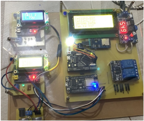
Integrated wiring of client and server systems is shown in Figure 4.
Based on Figure 4, it can be explained that the integrated wiring on the embedded device prototype for connecting client and server systems,
Figure 4. Integrated wiring of client and server systems
4.1.2 Programming for microcontrollers and smart-phones
Programming the real-time IoT-based monitoring system prototype and measuring battery cell voltage values is used for the operating mechanism of the system prototype, so that it can operate according to the operating principle. Programming algorithms for client and server systems is shown in Figure 5.
Input to the microcontroller system is in the form of a voltage value, then the system processes it based on programming with the output in the form of displayed digital data and alarm conditions. The stages in programming the Arduino IDE-based Arduino board, namely (i) providing raw-files for Arduino IDE to be installed on a PC, (ii) determining the algorithm and writing syntax based on Arduino IDE, (iii) compiling the structure of the program syntax in the Arduino IDE window on PC, and (iv) uploading syntax structure from PC to microcontroller system. Fulfilling the need to monitor each battery cell voltage value, the Blynk IoT application is needed. The stages of installing an application on a smart-phone, starting with downloading the Blynk IoT application via Play-store, followed by creating an account, and setting up the application for the existence of a system prototype.
4.2 Performance of the embedded device prototype
The performance of the prototype system for monitoring and measuring system voltage values and battery cells in real-time based on IoT is based on (i) measurement of the voltage value of each battery cell and the display displayed on the LCD and smartphone screen and (ii) performance measurement on setting settings for alarm conditions when a decrease in the value of the battery cell voltage. The physical appearance of the client and server systems when they are operated is shown in Figure 6.
Based on Figure 6, it can be explained that the embedded device prototype is ready to be operated for performance measurement.
#a) programming algorithms on the client system
#a) programming algorithms on the server system
Figure 5. Programming algorithms for client and server systems
Figure 6. The physical appearance of the client and server systems when they are operated
4.2.1 The voltage rating of each battery cell
The results of the first performance measurement of the system prototype, namely the measured battery cell voltage value and displayed on the LCD and smart-phone are compared to the results of the battery cell voltage measurement value based on the indication on the measuring instrument. Efforts to compare these values are used to validate the performance of the system prototype in the form of measurement results such as the methods and processes in previous studies. Display of battery cell voltage values # 1 and # 2 of the measurement results of the system prototype displayed on the LCD and measurement results on the multimeter are shown in Figure 7.
Figure 7. Display of battery cell voltage values # 1 and # 2 of the measurement results of the system prototype displayed on the LCD and measurement results on the multimeter
Figure 8. Display the voltage values of battery cells #1 and #2 on the smartphone screen
Based on Figure 7 it can be explained that the voltage value of battery cell #1 is displayed at 0.35 volts and battery cell #2 is displayed at 1.09 volts. The voltage value of battery cell #2 has been confirmed by the measurement results with the help of a multimeter, therefore that the data from the measurement of battery cell voltage #2 on the prototype system has been validated.
Display the voltage values of battery cells #1 and #2 on the smartphone screen is shown in Figure 8.
Based on Figure 8 it can be explained that the results of measuring the performance of the system prototype are in the form of displaying the voltage value of battery cell #1 of 1.27 volts and battery cell #2 of 1.15 volts on the smartphone screen. The success of monitoring and measuring cell voltage values is displayed on the smartphone screen as proof that the performance of the IoT-assisted prototype system is in accordance with the expected results.
4.2.2 Response to the setting for alarm condition when there is a decrease in the value of the battery cell voltage
The results of performance measurements on the system prototype are in the form of responses to the results of determining the settings for alarm conditions if there is a decrease in the battery cell voltage value. The setting for alarm condition on the system prototype is set at a value of less than 1 volt (voltage less than 1 volt) for each battery cell. For conditions where the measured battery cell voltage is less than 1 volt, the buzzer operates, the LED is lights up, and the Blynk IoT application sends notifications to smart-phones and e-mail addresses. Notification displays when there is a low voltage condition on the battery cells and is displayed on the smartphone screen as shown in Figure 7.
Figure 9. Notification displays when there is a low voltage condition on the battery cells and is displayed on the smartphone screen
Based on Figure 9 it can be explained, that when there is a measured battery cell voltage value of less than 1 volt, the Blynk IoT application sends a notification to the smartphone and the destination e-mail address.
Based on the results and discussion, conclusions can be drawn according to the research objectives. The real-time IoT-based battery voltage monitoring and measuring system prototype was carried out by (i) prototype design and (ii) prototype performance measurement. The prototype design was obtained by making mini-motherboards, assembling and wiring client and server systems, and programming Arduino IDE-based microcontrollers and smart-phones with the Blynk IoT application. Arduino IDE-based microcontroller programming with stages: i) provision of Arduino IDE raw files, ii) determination of algorithms and syntax in writing, and iii) compiling and uploading of syntax structures from a PC to Arduino board using a USB cable; while the programming stages for smart-phones assisted by the Blynk IoT application, include i) installing the Blynk IoT application on smart-phones via downloading on Play-store, ii) creating a Blynk IoT application account; and iii) application setup with prototype devices.
Measurement of the performance of the monitoring system prototype and measuring system voltage values and battery cells in real-time based on IoT, includes i) reading the voltage of each battery cell displayed and ii) testing the settings for alarm conditions when there is a decrease in the battery cell voltage value. The voltage reading for each battery cell is displayed, carried out by comparing the value of the battery voltage measured by the prototype displayed on the LCD and smart-phone with the measured value of the output voltage of the battery with the help of a multi-meter. Comparison is used to validate the measurement results of the prototype device. Testing on the setting of the alarm condition when there is a decrease in the battery cell voltage value based on the setting on the prototype device, which is less than 1 volt (battery cell voltage less than 1 volt), when the measured battery voltage is less than 1 volt, the buzzer operates, the LED lights up, and the Blynk IoT application sends notifications on smart-phones and to e-mail addresses.
The results of this research are two main things related to the two research objectives, therefore it is hoped that the purposes of this research, namely, the formation of a prototype system goes through a number of stages, so that a program structure can be made for its operation, then this is a requirement for the continued process in the form of measuring prototype performance, while achieving success when measuring performance, then it is a requirement for designing and making prototypes of similar systems based on microcontroller, Internet networking, and smart-phone.
Submission of suggestions for similar research related to the use of microcontrollers or other controllers for a prototype IoT-based monitoring system in the future, namely the creation of a monitoring system unit with a database-based online data record feature that can be accessible to smart-phones and PCs. Devices for monitoring a system are expected to be integrated with each other. All hardware and software must be selected to be cheap and easy to obtain, open source, and highly user-friendly.
|
IoT |
Internet of Things |
|
ES |
Embedded System |
|
ED |
Embedded Device |
|
UID |
Unique Identification |
|
ICT |
Information and Communication Technology |
|
QoS |
Quality-of-Service |
|
MCU |
Microcontroller Unit or μC |
|
RMS |
Real-time Monitoring System |
|
EWS |
Early Warning Systems |
|
ISP |
Internet Service Provider |
|
IDE |
Integrated Development Environment |
|
LCD |
Liquid Crystal Display |
|
ADC |
Analog to Digital Converter |
|
SDA |
Serial Data |
|
SCL |
Serial Clock |
|
LED |
Light Emitting Diode |
|
PC |
Personal Computer |
[1] Kumar, S., Tiwari, P., Zymbler, M. (2019). Internet of Things is a revolutionary approach for future technology enhancement: a review. Journal of Big Data, 6(1): 1-21. https://doi.org/10.1186/s40537-019-0268-2
[2] Kayyali, M. (2022). Internet of Things (IoT): Emphasizing its applications and emergence in environmental management—The profound cases. In: Paul, P.K., Choudhury, A., Biswas, A., and Singh, B.K. (eds) Environmental Informatics. Springer, Singapore. https://doi.org/10.1007/978-981-19-2083-7_11
[3] Mude, A., Mando, L.B.F. (2021). Implementasi keamanan rumah cerdas menggunakan internet of things dan biometric sistem. MATRIK: Jurnal Manajemen, Teknologi Informasi, dan Rekayasa Komputer, 21(1): 179-188. https://doi.org/10.30812/matrik.v21i1.1381
[4] ADB. (2018). Handbook on Battery Energy Storage System. Manila, Philippines: Asian Development Bank, 1-78. http://dx.doi.org/10.22617/TCS189791-2
[5] Suparman, R., Hamdani, H., Subarjo, A. (2021). Analisis uji kapasitas baterai pada gardu induk 150 kV di bantaeng new. prosiding seminar nasional teknik elektro dan informatika (SNTEI), Makassar, 21 September 2021. http://jurnal.poliupg.ac.id/index.php/sntei/article/view/2826.
[6] Zachari, Z., Purwanto, E., Nugraha, S.D. (2022). Rancang bangun battery charger CC-CV dengan forward converter. Power Elektronik: Jurnal Orang Elektro, 11(1): 16-20. http://dx.doi.org/10.30591/polektro.v11i1.2650
[7] Gupta, A.K., Johari, R. (2019). IOT based electrical device surveillance and control system. 2019 4th International Conference on Internet of Things: Smart Innovation and Usages (IoT-SIU), Ghaziabad, India, pp. 1-5. https://doi.org/10.1109/IoT-SIU.2019.8777342
[8] Hakim, L., Kristanto, S.P., Subono, S., Dinan, F.B. (2022). Internet of Things-based power factor monitoring system using android. Techno.com., 21(2): 364-377. https://doi.org/10.33633/tc.v21i2.5898
[9] Adam, B.B., Hilda, H., Priyatman, H. (2019). Sistem real-time monitoring transformator distribusi berbasis Internet of Things (IoT). Jurnal Teknik Elektro Universitas Tanjungpura, 2(1): 1-6.
[10] Hapsari, H., Winanda, A., Prastowo, H., Pitana, T. (2021). Real time fuel consumption monitoring system integrated with Internet of Things (IoT). KAPAL: Jurnal Ilmu Pengetahuan dan Teknologi Kelautan, 18(2): 88-100. https://doi.org/10.14710/kapal.v18i2.37180
[11] Nistor, A., Zadobrischi, E. (2022). Analysis and estimation of economic influence of IoT and telecommunication in regional media based on evolution and electronic markets in Romania. Telecom, 3(1): 195-217. https://dx.doi.org/10.3390/telecom3010013
[12] Chegini, H., Naha, R.K., Mahanti, A., Thulasiraman, P. (2021). Process automation in an IoT–Fog–Cloud ecosystem: A survey and taxonomy. IoT, 2(1): 92-118. https://doi.org/10.3390/iot2010006
[13] Atwa, O.S.E. (2019). Batteries. Practical Power System and Protective Relays Commissioning, 157-162. https://dx.doi.org/10.1016/b978-0-12-816858-5.00015-0
[14] Sianturi, R. (2019). Volt Baterai and Cell Monitoring (VBCM). Paper of PT PLN (Persero) UITJBT UPT Bogor, edisi 8. PT PLN (Persero) UITJBT UPT Bogor, 1-15.
[15] Aminullah, M.Y. (2018). Penggantian Battere 110V Unit 1 GI Jekulo. Laporan Pelaksanaan on the Job Training Prajabatan Tingkat SMK-Jalur Pelaksana, edisi 14. PT PLN (Persero) UITJBT, Pati, 1-34.
[16] IEEE Spectrum. (2017). Chip Hall of Fame: Microchip Technology PIC 16C84 Microcontroller: Adding easily reprogrammable onboard memory to store software revolutionized microcontroller. History of Technology. https://spectrum.ieee.org/chip-hall-of-fame-microchip-technology-pic-16c84-microcontroller.
[17] Prayitno, B., Palupiningsih, P. (2019). Prototipe sistem monitoring penggunaan daya listrik peralatan elektronik rumah tangga berbasis Internet of Things. Petir: Jurnal Pengkajian dan Penerapan Teknik Informatika, 12(1): 72-80. https://dx.doi.org/10.33322/petir.v12i1.333
[18] Prayudyanto, M.N., Goeritno, A., Al Ikhsan, S.H., Taqwa, F.M.L. (2022). Designing a model of the early warning system on the road curvature to prevent the traffic accidents. International Journal of Safety and Security Engineering, 12(3): 291-298. https://doi.org/10.18280/ijsse.120303
[19] Wahid, S.N., Hartanto, A.D. (2021). Sistem monitoring alarm peringatan banjir dan fitur motor servo untuk buka tutup pintu air menggunakan algoritma background subtraction. Indonesia Journal of Technology Informatics Science, 2(2): 60-66. https://doi.org/10.24176/ijtis.v2i2.5747
[20] Dinata, S. (2018). Perancangan human machine interface simulator gardu induk 150 kV. EPIC (Journal Electr. Power, Instrum. Control), 1(1): 1-8. http://dx.doi.org/10.32493/epic.v1i1.1556
[21] Mustaqim, A.S., Kurnianto, D., Syifa, F.T. (2020). Implementasi teknologi internet of things pada sistem pemantauan kebocoran gas LPG dan kebakaran menggunakan database pada google firebase. Elektron: Jurnal Ilmiah, 12(1): 34-40. https://doi.org/10.30630/eji.12.1.161
[22] Hasan, N.K. (2021). Rancang bangun sistem monitoring posisi dan kecepatan kapal secara online berbasis mobile android. Jurnal Teknik Elektro dan Komputer: TRIAC, 8(1): 7-14. https://doi.org/10.21107/triac.v8i1.10066
[23] Hasibuan, R.I. (2021). Rancang Bangun Sistem Monitoring Output Panel Surya Berbasis Mikrokontroler Atmega 8 dengan Menggunakan IoT. Repository of Institusi Univ. Sumatera Utara, 1-75. https://repositori.usu.ac.id/handle/123456789/30503, accessed on Jan. 30, 2022.
[24] Effendi, R., Goeritno, A., Yatim, R. (2015). Prototipe sistem pendeteksian awal pencemaran air berbantuan sensor konduktivitas dan suhu berbasis mikrokontroler. Prosiding Seminar Nasional Sains dan Teknologi, Jakarta.
[25] Ginting, S.F., Goeritno, A., Yatim, R. (2016). Kinerja sistem pengontrolan berbantuan sensor voice recognition dan mikrokontroler ATmega16 untuk Pengoperasian Aktuator. di Prosiding SNTI, 359-365.
[26] Guven, Y., Cosgun, E., Kocaoglu, S., Gezici, H., Yismazlar, E. (2017). Understanding the concept of microcontroller based systems to choose the best hardware for applications. Research Inventy: International Journal of Engineering and Science, 6(9): 38-44.
[27] Goeritno, A., Mustofa, I. (2017). Minimum System Berbasis Mikrokontroler ATmega32 untuk Pemantauan dan Tampilan Kondisi Instalasi Kelistrikan Otobis. Jurnal Ilmiah Setrum, 6(1): 55-67. http://dx.doi.org/10.36055/setrum.v6i1.1721
[28] Sholehati, M.T., Goeritno, A. (2018). Sistem minimum berbasis mikrokontroler ATmega2560 sebagai sistem pengaman pada analogi lemari penyimpanan brankas. Jurnal Rekayasa Elektrika, 14(3): 158-166. http://dx.doi.org/10.17529/jre.v14i3.11649
[29] Goeritno, A., Afandi, M.Y. (2019). Modul elektronika berbasis mikrokontroler sebagai sistem pengaman pada mobil terintegrasi dengan engine immobilizer. Jurnal Rekayasa Elektrika, 15(2): 75-84. http://dx.doi.org/10.17529/jre.v15i2.12872
[30] Prakoso, B.A., Goeritno, A., Prakosa, B.A. (2020). Pemanfaatan mikrokontroler AVR untuk pengendalian sejumlah parameter fisis pada analogi smartgreenhouse. Jurnal Ilmiah SETRUM, 9(1): 52-59. http://dx.doi.org/10.36055/setrum.v9i1.8055
[31] Suhendri, S., Goeritno, A. (2018). Pemantauan energi listrik pada satu kWH-meter fase tunggal untuk empat kelompok beban berbasis metode payload data handling. Jurnal Rekayasa Elektrika, 14(3): 189-197. http://dx.doi.org/10.17529/jre.v14i3.11952
[32] Setyawibawa, I., Goeritno, A. (2019). Communication interface adapter berbasis mikrokontroler arduino terkendali sinyal dual tone multi frequency. Jurnal ELKHA, 11(1): 19-26. http://dx.doi.org/10.26418/elkha.v11i1.30374
[33] Suhartono, D., Goeritno, A. (2019). Prototipe sistem berbasis mikrokontroler untuk pengkondisian suhu pada analogi panel dengan analogi sistem air conditioning. Jurnal EECCIS (Electrics, Electronics, Communications, Controls, Informatics, Systems), 13(1): 22-30.
[34] Goeritno, A., Hendrian, F., Ritzkal, R. (2019). Pengendalian lampu pijar pada analogi instalasi listrik fase-tiga melalui smartphone berbasis android berbantuan jaringan Wi-Fi. Jurnal Ilmiah SETRUM, 8(2): 274-286. http://dx.doi.org/10.36055/setrum.v8i2.6977
[35] Nasyarudin, A.F., Ritzkal, Goeritno, A. (2020). Prototipe perangkat untuk pemantauan dan pengendalian berbasis web diiintegrasikan ke smarthome system. IJEIS (Indonesian Journal of Electronics, Instrumentation, and System), 10(2): 167-178. http://dx.doi.org/10.22146/ijeis.58316
[36] Fazry, H.A., Goeritno, A. (2020). Sistem minimum dengan battery back-up berbasis mikrokontroler arduino untuk pengoperasian inkubator. Jurnal Ilmiah SETRUM, 9(2): 115-126.
[37] Hardian, L., Goeritno, A. (2021). Pabrikasi unit kontrol berbasis web pada smarthome system untuk pengoperasian pintu gerbang. Jurnal RESTI (Rekayasa Sistem dan Teknologi Informasi), 5(1): 163-173. https://doi.org/10.29207/resti.v5i1.2879
[38] Darussalam, D., Goeritno, A. (2021). Pemanfaatan RFID, loadcell, dan sensor infrared untuk miniatur penukaran botol plastik bekas. Jurnal RESTI (Rekayasa Sistem dan Teknologi Informasi), 5(2): 281-291. https://doi.org/10.29207/resti.v5i2.3048
[39] Goeritno, A., Hendryan, F. (2022). Monitoring dan kendali tegangan jaringan listrik fase-tiga melalui smartphone. Jurnal RESTI (Rekayasa Sistem dan Teknologi Informasi), 6(2): 32-40. https://doi.org/10.29207/resti.v6i1.3662
[40] Fauji, A. Goeritno, A., Hardian, L., Prakoso, B.A. (2022). Embedded device pada smarthome system berbasis iot untuk pengoperasian pintu gerbang terkendali melalui smartphone. Jurnal Rekayasa Elektrika, 18(1): 1-12. http://dx.doi.org/10.17529/jre.v18i1.22224
[41] Wicaksono, N.A., Goeritno, A. (2022). Designing an arduino board-based electronic device driven by GRBL gru to operate the mini PCB printing machine. Jurnal Rekayasa Elektrika, 18(3): 165-174. https://doi.org/10.17529/jre.v18i3.25923
[42] Media’s, E., Syufrijal, S., Rif’an, M. (2019). Internet of Things (IoT): BLYNK framework for smart home. KnE Social Sciences, 3(12): 579-586. https://doi.org/10.18502/kss.v3i12.4128
[43] Goeritno, A., Herutama, Y. (2018). Prototipe sistem elektronis berbantuan pc untuk pemantauan kondisi pasokan daya listrik. Jurnal Rekayasa Elektrika, 14(2): 96-104. http://dx.doi.org/10.17529/jre.v14i2.10904
[44] Goeritno, A., Prayudyanto, M.N., Eosina, P., Siregar, T.H., Waluyo, R. (2023). PDE-based mathematical models to diagnose the temperature changes phenomena on the single rectangular plate-fin. Mathematical Modelling of Engineering Problems, 10(1): 266-275. https://doi.org/10.18280/mmep.100131
[45] RemoteXY.com. (n.d.). Editor of Graphical Interface. https://remotexy.com/en/help/editor/, accessed on June 22, 2020.
[46] Shirriff, K. (2016). The surprising story of the first microprocessors. IEEE Spectrum, 53(9): 48-54. https://doi.org/10.1109/MSPEC.2016.7551353
[47] Goeritno, A., Nurmansyah, D., Maswan, M. (2020). Safety instrumented systems to investigate the system of instrumentation and process control on the steam purification system. International Journal of Safety and Security Engineering, 10(5): 609-616. https://doi.org/10.18280/ijsse.100504
[48] Goeritno, A., Nugraha, I., Rasiman, S., Johan, A. (2020). Injection current into the power transformer as an internal fault phenomena for measuring the differential relay performance. Instrumentation Mesure Metrologie, 9(6): 443-451. https://doi.org/10.18280/i2m.190605
[49] Goeritno, A., Setyawibawa, I., Suhartono, D. (2021). Designing a microcontroller-based half-duplex interface device drove by the touch-tone signal. Jurnal Infotel, 13(4): 205-215. https://doi.org/10.20895/infotel.v13i4.712
[50] Goeritno, A., Setyawibawa, I. (2021). An electronic device reviewed by diagnosing on the modules embodiment. International Journal of Electronics and Communication Systems, 1(2): 41-55. http://dx.doi.org/10.24042/ijecs.v1i2.10383