Ngoc Thai Huynh![]() | Hoang Vinh Nguyen
| Hoang Vinh Nguyen![]() | Duc Phuong Nam Nguyen
| Duc Phuong Nam Nguyen![]() | Minh Hung Vu*
| Minh Hung Vu*![]() | Quoc Manh Nguyen
| Quoc Manh Nguyen![]()
© 2025 The authors. This article is published by IIETA and is licensed under the CC BY 4.0 license (http://creativecommons.org/licenses/by/4.0/).
OPEN ACCESS
In this investigation, the aerodynamic and structural behavior of an offshore wind turbine blade was investigated under varying flow velocities and pitch angles. The objective of this study was to demonstrate the feasibility of integrating aerodynamic flow analysis with structural FEM durability assessment to better understand the combined effects on offshore wind turbine blade performance. A range of simulations was conducted to observe how changes in inlet wind speed (from 50 m/s to 90 m/s) and blade pitch angle (from 8° to 12°) influenced velocity distribution, aerodynamic loading, mechanical stress, and deformation. Velocity magnitudes over the blade increased significantly with higher inlet speeds, with streamline behavior shifting further downstream, indicating intensified wake development. The rotational speed of the rotor (maintained at 15 rpm) introduced twisting flow patterns over the blade surfaces, affecting the pressure distribution and leading to variations in lift. Mechanical deformation and equivalent stress were shown to increase with airflow velocity, ranging from 0.39 mm and 0.73 MPa to 6.06 mm and 11.583 MPa. Similarly, changes in blade pitch angle resulted in shifts in aerodynamic load distribution, though stresses remained within the material’s strength limits. Stress concentrations were consistently located at the mid-span of the blade, while deformation extended from the center to the trailing edge. Despite elevated loads, the maximum stress of 152.6 MPa remained below the material’s yield strength, ensuring structural stability.
offshore wind turbine blade power, aerodynamic analysis, structural analysis, pitch angle, flow velocity, CFD simulation
Worldwide, wind turbine technology, especially blade design, has been developed over several decades. Countries with advanced wind power industries like Denmark, Germany, the US, China, and Spain have heavily invested in optimizing blade aerodynamics, materials, and manufacturing techniques to enhance efficiency and durability. The shape and length of the turbine blades greatly affected the power output as well as the durability of the turbine blades. Aerodynamic analysis tools have been widely applied as a premise for structural optimization. Lightweight materials such as composites and fiberglass polymers were also used for manufacturing. Basically, these materials were lightweight, durable and have a very long life. In addition, smart materials were also used. Turbine blades were manufactured using 3D printing technology. To maximize power output, researchers have also tested turbine blades with a length of up to 100 m. Reducing manufacturing costs, increasing life and obtaining high power output were major challenges for researchers. In addition, the climate of each different region also affected the turbine blades.
To maximize the power output from wind turbine blades as well as the ability to withstand storms. Especially low manufacturing costs, researchers have been aiming at optimizing aerodynamics, optimizing structural strength and reducing weight. Research to improve the lightweight offshore wind turbine blades by researching material improvements but still obtaining high power output and high mechanical strength.
The aerodynamics of the turbine blades have increased the power factor up to 47.8% thanks to the integration of vortex generators to slow down the flow separation effect [1]. This problem indicated that if it wanted to increase the power output of the wind turbine, the flow need to control well. Optimizing the structure of the wind turbine blades to reduce weight while ensuring mechanical strength is based on the results of aerodynamic analysis with different materials and thicknesses [2]. This method minimizes risks, reduced the cost of experimental manufacturing while still ensuring the strength and life of the structure.
The shape of the wind turbine blade was optimized by genetic algorithm based on the results of aerodynamic analysis and finite element analysis. The main parameters selected were the chord length, helix angle and material thickness. The results showed that the aerodynamic performance was significantly improved and the structural rigidity of the turbine blade was ensured [3]. The radius of the turbine blade is the most influential factor on the aerodynamic performance, and it was confirmed that there is a significant interaction between the shape and the aerodynamic behavior of the turbine blade [4]. In addition, the genetic algorithm was also applied to optimize small turbines to increase power output and lift [5]. The deep learning method was also applied to achieve the optimal wind turbine blade to reduce weight, reduce design cost and improve aerodynamic performance and power output [6]. Power factor up to 70% by using OpenFOAM to analyze the aerodynamics of wind turbine blades leads to improved wind farm layout efficiency [7]. Aerodynamic efficiency of wind turbine blades is improved by artificial intelligence and new materials [8].
The aerodynamic efficiency and power generation efficiency of wind turbines were reduced due to the turbine blades working in a stormy environment causing the wind turbine blades to wear [9]. In this study, the Ffowcs Williams and Hawkings approach was used to model the aerodynamic noise of the turbulent flow field. The results of this method showed that the worn blades had a larger noise than the normal blades. The momentum theory for the bee swarm element [10] was applied to optimize the aerodynamic model of the small-scale wind turbine blade. The aerodynamic efficiency of the small turbine blade was significantly improved and confirmed by experiments and achieved a maximum power of up to 1.46 kW at a wind speed of 10 m/s. The windward state of the leading and trailing edges was compared to determine the aerodynamic efficiency and efficiency of the wind turbine blade [11]. Simulation and experimental results show that the load acting on the wind turbine blade is significantly reduced by up to 57.8% when catching the wind at the trailing edge.
The aerodynamic efficiency of wind turbines was degraded when ice forms on the blades, leading to a reduction in the area. For this reason, an optimization method based on the turbine blade momentum and a tool to predict ice formation on horizontal axis wind turbine blades under different ice formation conditions was developed. The results of this method indicate that the Aeolos-H 30 kW and NREL 5 MW wind turbines under ice formation conditions lasting up to 1 hour have a 4% reduction in power output [12]. Determining the aerodynamic loads on offshore wind turbine blades was difficult. Therefore, the aerodynamic behavior of the wind turbine blades was tested in a wind tunnel to determine the optimal model using a genetic algorithm. The aerodynamic performance of the DTU 10 MW NREL 5 MW wind turbine blade was found to be comparable to the prototype over the wind speed range and was validated using Aerodyn software [13]. A new turbine blade hybridized from the two previous blades S809 and NACA 63215 has improved aerodynamic performance by various experiments such as surface oil flow visualization at high wind speeds, plume visualization at low wind speeds, six-force-moment balancer and hot wire anemometry. The lift coefficient of the new wind turbine blade has doubled compared to the two blades S809 and NACA 63215. Heel moment and pitch angle were also higher [14]. To predict the aerodynamic load of wind turbine blades with the desire of the fastest calculation speed, the artificial neural network model consists of a time-independent multilayer perceptron network (MLP), a time-dependent long short-term memory network (LSTM) and a time-dependent convolutional neural network (CNN). The results of these three models show that the CNN model achieves the highest accuracy compared to the other two models. And another advantage of the CNN model is that it is easy to train and obtains results faster [15]. Low cost is always the top criteria for the design and manufacture of wind turbine blades. One of the best solutions to achieve high efficiency for this problem is to optimize the structure of the turbine blade. Conjugate gradient has been used to solve 1894 design variables of the thickness of the root of the wind turbine blade. The result of this method also significantly reduces the mass of the wind turbine blade and controls the problem of fatigue and high-cost behavior that is difficult to solve [16].
Glass fiber reinforced polymer (GFRP) composite materials have been used to fabricate wind turbine blades to reduce the influence of aerodynamic loads on wind turbine blades. Tests have confirmed that this new wind turbine blade has outstanding advantages in terms of stable power output at all wind speeds, fast starting, and efficient shutdown mechanism at high speeds [17]. To improve mechanical properties, graphene has been applied to fabricate wind turbine blades, resulting in high power generation efficiency and reduced manufacturing costs. The results have confirmed that graphene reinforcement on wind turbine blades brings high efficiency [18]. When icing occurs on the wind turbine blades, the mechanical properties of the wind turbine blades were reduced. The location of the maximum stress and strain can vary due to the formation of ice on the surface of the turbine blades. This problem is due to the decrease in temperature, the increase in wind speed, leading to an increase in the thickness of the ice layer while other conditions were fixed [19].
The environmental impact on the aerodynamics of wind turbine blades has been controlled by replacing glass and carbon fibers in the materials used to make offshore wind turbine blades with natural fibers such as flax, hemp, and basalt. This not only takes advantage of recycling waste to reduce the negative impact on the aerodynamics of wind turbine blades. It also limits global warming [20]. The application of composite materials has effectively improved the aerodynamic performance of wind turbine blades, increased durability, and environmental compatibility. The practical application of this technology is carried out by the Gansu Wind Farm, Hornsea One Wind Farm, and Block Island Wind Farm [21]. The incorporation of inexpensive materials such as spherical balsa wood pellets, polyurethane, and glass fiber reinforced polymer composites by crushing into concrete for recycling wind turbine blades has significantly improved the mechanical performance and carbon emissions, in addition to improving the flexural strength. Waste has been reduced, which negatively affects the performance of concrete over time. This is not only an effective solution for recycling wind turbine blades, but also an effective solution for protecting the environment [22].
Fault detection techniques were critical for maintaining turbine reliability and minimizing downtime. UAV-based inspections combined with deep learning have revolutionized surface damage detection. The DCW YOLO model, integrating advanced convolutional modules such as DSConv and CARAFE with a WIoU loss function, has demonstrated superior accuracy over previous models like YOLOv8n, achieving mAP improvements from 91.4% to 93.8% at 0.5 IoU and from 68.9% to 71.2% at 0.5–0.95 IoU [23]. Such accuracy enhancements were vital for early damage identification and timely maintenance. Non-destructive testing methods, including laser Doppler vibrometry, enable contactless detection of blade cracks, enhancing inspection safety and efficiency [24]. Thermal and RGB image-based deep learning models have achieved perfect accuracy in defect detection, reflecting the maturity of AI applications in condition monitoring [25]. Additionally, UAV-based X-ray inspections combined with deep learning facilitate precise localization of internal cables without disassembly [26]. Comparative analyses reveal that YOLOv9 outperforms Mask R-CNN in fault detection accuracy, offering more reliable operational inspection tools [27]. Drone inspections employing Transfer Xception deep learning models have achieved nearly 100% fault recognition accuracy, signaling readiness for widespread industrial deployment [28].
The ultimate objective is to integrate these advances into cohesive systems optimizing wind farm layouts and large-scale blade designs. Particle swarm and reinforcement learning algorithms have been applied to optimize layouts and blade designs, achieving power conversion efficiencies up to 98.68%, surpassing traditional design strategies [29]. Complementing these efforts, a 20 MW offshore blade design upgrade has delivered approximately 80% increases in power and thrust, significantly contributing to net-zero emission targets [30].
A bending and torsion experiment was conducted to determine the aerodynamic behavior and mechanical strength of the wind turbine blade. Measurements of bending deflection, strain rate, frequency and natural modes were performed and the measured values were recorded [31]. The failure process of the wind turbine blade was recorded by experiments and finite element simulation. The results showed that the transition region of the wind turbine blade often caused blade damage. The bending of the turbine blade also contributed significantly to this failure [32]. The finite element method is applied to the aerodynamic analysis of wind turbine blades to confirm the accuracy of the fully parameterized modeling method. The 3D solid/shell element model is parametrized with spline curves for the wind turbine blade structure, and the blade is experimentally validated according to IEC 61400-23. The experimental results confirm that the simulation results were in good agreement at the global level, with the need for improvement of the local analysis and torsional response [33]. To detect faults in wind turbine blades, a miniature turbine blade model was fabricated by 3D printing method for experimentation, Finite element method and machine learning were applied. The NREL 5MW turbine blade model with simulated cracks was analyzed for vibration and natural frequency by impact test method. ANOVA analysis was applied to analyze the collected data, machine learning algorithms (SVM and KNN) were applied to analyze the faults with an accuracy of over 94%. The results showed that all vibration modes significantly affect the damage, this solution is effective in monitoring the condition of wind turbine structures.
The research combines aerodynamic analysis and structural strength analysis of offshore wind turbine blades subjected to strong storms. This research aims to analyze the aerodynamic behavior of offshore wind turbine blades when the wind speed changes. This is done and records the impact of storms, cyclones and pitch angles on the structure with changing inlet air flow rates. In addition, this research also checks the structural strength by analyzing the strength in ANSYS against the strong impacts of storms and pitch angles on the offshore wind turbine blade structure.
Although advances have been made in aerodynamic optimization and structural durability of wind turbine blades, these areas were often studied separately. In offshore wind turbines, the combined effects of harsh environmental conditions on both aerodynamics and durability remain underexplored. Specifically, how aerodynamic loads interact with structural fatigue and surface degradation over time is not well understood. This research aims to fill this gap by integrating aerodynamic analysis with durability assessment to improve blade performance and lifespan in offshore environments.
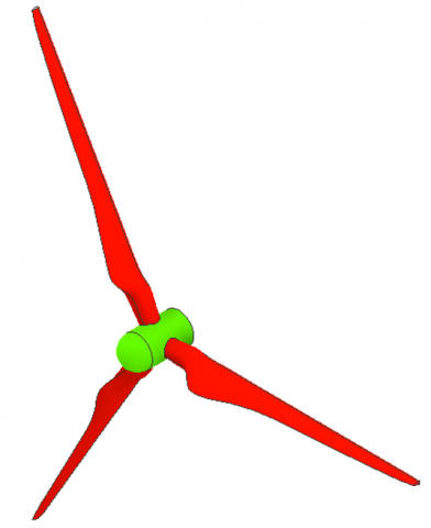
The offshore wind turbine blade model is designed using Inventor software as illustrated in Figure 1. The spatial structure of the blades consists of three blades symmetrically around the green cylindrical axis. The wind turbine blades were designed to be tapered and twisted to increase aerodynamic efficiency and power output. This model is similar to the actual shape of the turbine for aerodynamic analysis and structural strength analysis. The analysis results serve as a basis for optimizing turbine performance in offshore storm conditions.
Figure 1. The offshore three-bladed wind turbine power model
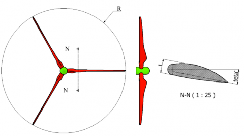
A view of an offshore wind turbine blade was shown in Figure 2. The blades were arranged symmetrically around a central axis. The blade twist and thickness were clearly shown in this view, and the model dimensions such as radius and maximum thickness were shown in this figure. The radius of the designed turbine blade was measured at 59 meters. The angle of inclination of the blade relative to the horizontal line, referred to as the pitch angle (Teta), was varied at three levels: 8°, 10°, and 12°. The thickness of the turbine blade was designed as 650 mm. Aluminum alloy, magnesium alloy, and titanium alloy were selected as the materials for the turbine blades in the simulation.
Figure 2. Drawigng 2D of the offshore three-bladed wind turbine power model
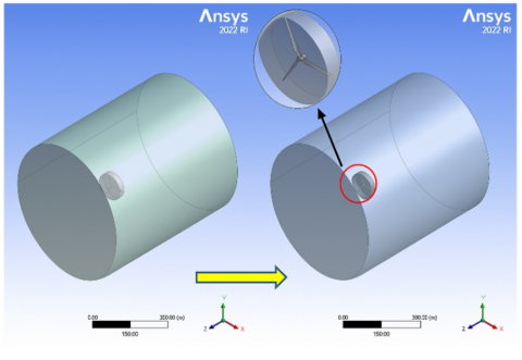
To simulate the relationship between the environment and wind turbine building, Boolean operation was used to define the computational domains for air. The features and details of these procedures, including the subtract operation that generates flow regions around the model shape, were compiled in Table 1.
Table 1. Using Boolean operation command to create obstacles in the environment
|
Details of Boolean1 |
|
|
Boolean operation |
Boolean1 Subtract |
|
Target Bodies |
2 Bodies |
|
Tool Bodies |
1 Body |
|
Tool Bodies? |
No |
The fluid domain after Boolean operation subtraction as shown in Figure 3, makes it easy to distinguish between fluid flow channels and structural boundaries. This is the resulting computational domain. This step is important for accurate mesh generation and boundary condition setting during the simulation.
Figure 3. Outcomes of domain creation
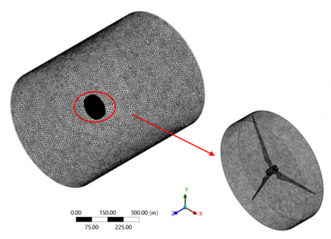
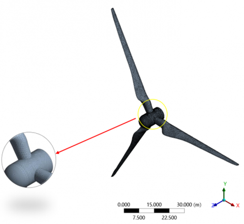
The detailed integration of the rotor mesh within the global computational domain was depicted in Figure 4. The left part of the figure highlights the refined mesh region around the rotor with a red ellipse, emphasizing the high-resolution elements where complex flow interactions were expected. The right part presents a zoomed-in view of the meshed three-bladed propeller, clearly depicting the dense mesh distribution along the blade surfaces. This integrated meshing strategy ensures accurate coupling between the rotating blades and the surrounding fluid, which is crucial for capturing the aerodynamic performance of the offshore wind turbine system.
Figure 4. Mesh result
The mesh parameters used in the simulation environment were compiled and presented in Table 2. During the meshing process, mechanical physics preferences were followed to ensure appropriate resolution and accuracy for the offshore wind turbine blade analysis. An overall element size of 700 mm was applied, and the arrangement of elements was controlled automatically by the simulation program. To improve mesh quality in regions with complex geometry, adaptive scaling was employed, allowing for automatic refinement of the mesh where necessary. Additionally, defeaturing techniques were implemented to remove small, non-essential geometric details that could otherwise increased computational cost without contributing significantly to the simulation results. To improve the accuracy and reliability of the simulation, the minimum mesh size at small locations near complex surfaces and important transition zones was 0.03 meters. This meshing method was used to improve computational efficiency. This is necessary when performing aerodynamic analysis of offshore wind turbine blades.The meshing result for the computational domain was 1890732 triangular elements and 2612046 nodes. The turbine blade was meshed automatically with the mesh size 0.03 meters. The meshing result for the turbine blade was 50234 triangular elements 89737 nodes.
Table 2. Parameters to set for creating mesh
|
Display |
|
|
Display style |
Use Geometry setting |
|
Defaults |
|
|
Physics preference |
Mechanical |
|
Element Order |
Program Controlled |
|
Element size |
700.0 mm |
|
Sizing |
|
|
Use Adaptive sizing |
Yes |
|
Resolution |
Default (2) |
|
Mesh Defeaturing |
Yes |
|
Defeature size |
20 mm |
|
Transition |
Fast |
|
Span Angle center |
Coarse |
|
Initial Size Seed |
Assembly |
|
Bounding Box Diagonal |
68739 mm |
|
Average Surface Area |
37295000 mm2 |
|
Minimum Edge Length |
0.03 |
|
Nodes |
2612804 |
|
Elements |
1891248 |
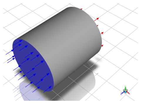
The boundary conditions applied to a cylindrical geometry in ANSYS Fluent for a Computational Fluid Dynamics (CFD) simulation were shown in Figure 5. The left face of the cylinder is assigned a velocity inlet boundary condition, with the direction and magnitude of the incoming flow indicated by blue arrows. Pressure outlets were defined on the side and rear surfaces, represented by red arrows, through which fluid is allowed to exit the domain. The calculation model was set up as a space containing air flowing through the offshore wind turbine blades. When passing through this turbine blade, the response of the air flow will change and impact the structure, affecting the aerodynamics and power output. And can cause damage to the offshore wind turbine blades. The average wind speed is set to 50 m/s, 70 m/s and 90 m/s respectively. To perform aerodynamic analysis. While other parameters were fixed. The air properties were set by default of ANSYS fluent software and the ambient temperature is constant at 288.16 K (15℃). In this model, the flow was set to be similar to the real outside.
Figure 5. Fluent module view
The simulation settings and physical properties used in the study were systematically organized into several categories, as shown in Table 3. The seawater density was specified as 1020 kg/m³. A pressure-based solver was employed, with the velocity formulation set to absolute. The simulation was conducted under steady-state conditions, and the gravitational acceleration in the vertical (Y) direction was set to -9.81 m/s².
Table 3. Settings in fluent
|
Category |
Setting/Value |
|
Solver |
Pressure Based |
|
Velocity formulation |
absolute |
|
Time |
steady |
|
Y gravity (m/s2) |
-9.81 |
|
Models |
|
|
Viscous |
Laminar |
|
Air |
|
|
Density (Kg/m3) |
1.225 |
|
Viscosity Kg/m s) |
1.7894e-05 |
|
Boundary conditions |
|
|
Inlet Air (m/s) |
|
|
Outlet |
|
|
Prevent Reverse Flow |
Yes |
|
Velocity specification method |
magnitude, normal to the boundary |
|
Reference frame |
absolute |
|
Solution methods |
|
|
Pressure-velocity coupling |
Yes |
|
Scheme |
coupled |
|
Spatial discretization |
|
|
Gradient |
Least Squares Cell-based |
|
Pressure |
Second-order |
|
Momentum |
Second-order Upwind |
|
Pseudo transient |
yes |
|
Pressure |
0.5 |
|
Momentum |
0.5 |
|
Density |
1 |
|
Body forces |
1 |
|
Number of iterations |
100 |
Regarding physical models, laminar viscous flow was considered. The properties of the fluids involved were defined as follows: air density was set at 1.225 kg/m³ with a viscosity of 1.7894 × 10⁻⁵ kg/m·s, while water-liquid density and viscosity were defined as 998.2 kg/m³ and 0.001003 kg/m·s, respectively.
Boundary conditions were applied with an inlet air velocity of 50 m/s. At the outlet, reverse flow prevention was activated, and velocity was specified based on magnitude and normal direction relative to the boundary. The reference frame was maintained as absolute throughout the simulation.
The solution methods incorporated pressure-velocity coupling, which was enabled, and a coupled scheme was selected. Spatial discretization schemes included a least squares cell-based gradient method, second-order pressure discretization, and second-order upwind momentum discretization. Pseudo-transient formulation was applied, with relaxation factors set to 0.5 for both pressure and momentum, 1 for density, and 1 for body forces. The simulation was run for a total of 100 iterations.
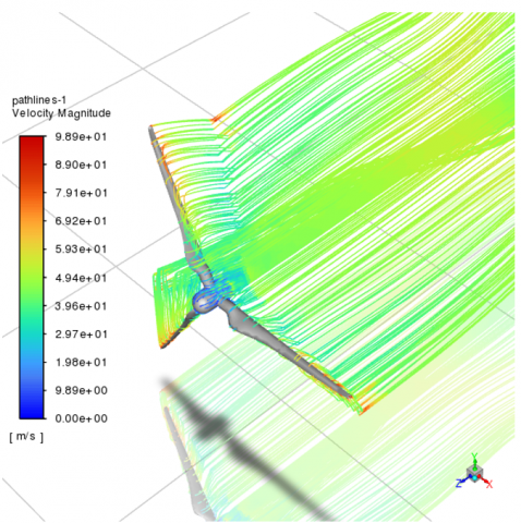
The variation in velocity magnitude around the wind turbine blades was thoroughly analyzed as the pitch angle (θ) was increased from 8° to 10° and then 12° as demonstrated in Figure 6. At the initial pitch angle of 8°, the velocity field around the blade surfaces was found to be relatively uniform, with peak velocities reaching approximately 98.9 m/s. Under these conditions, the airflow remained fully attached to the blade surfaces, maintaining smooth streamlines and resulting in minimal turbulent wake formation near the blade tips. This indicated efficient aerodynamic performance with low drag and steady lift generation.
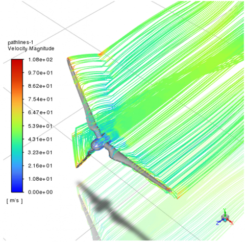
Upon increasing the pitch angle to 10°, a discernible increase in velocity magnitude was observed, particularly concentrated near the leading edge of the blades, where maximum velocities rose to 108 m/s. This local acceleration of the flow was attributed to the increase in pressure gradient, which increases the suction force on the upper blade surface and thus increases the lift force. The increase in velocity gradient near the leading edge indicates an improvement in aerodynamic loading, which was beneficial for the extraction of power from the wind.
a) Pitch angle = 8°
b) Pitch angle = 10°
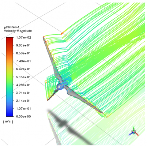
c) Pitch angle = 12°
Figure 6. Aerodynamic analysis results at different θ angle
The increase in flow velocity increases the pressure acting on the wind turbine blades. It also increases the lift force on the wind turbine blades. With the current turbine blade structure, the aerodynamic loading of the turbine blades has been improved. This not only increases the power output but also reduces damage to the turbine blades.
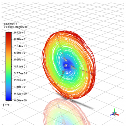
The increase in the inclination of the wind turbine blades by 12° has increased the velocity of the gas flow after passing the turbine blades, which also increases the power output obtained, the velocity of the gas flow through the turbine blades has increased to 107 m/s while the inlet velocity was only 90 m/s. This causes a more pronounced pressure difference between the suction and pressure sides of the wind turbine blades, which increases the aerodynamic thrust and power output. However, this also causes unfavorable pressure concentrations near the blade tips and creates flow separation. The overall efficiency of the turbine was reduced because the separated flow regions increase aerodynamic drag by disrupting the stability of the airflow and causing unstable loads on the offshore wind turbine blades. Changing the blade pitch angle significantly changes the velocity of the airflow passing through the offshore wind turbine blades, which negatively affects the aerodynamic behavior of the wind turbine blades. Meanwhile, a moderate blade pitch angle helps the airflow to be stable when passing through the wind turbine blades. Therefore, to increase the power, it was only necessary to increase the airflow velocity to increase the pressure gradient. However, excessive increase will cause damage to the turbine blades due to flow separation and airflow turbulence affecting the aerodynamic efficiency. Thus, an optimal study will create a balance of lift force to help the airflow stabilize when passing through the turbine blade to maximize the aerodynamic efficiency and reliability of the offshore wind turbine blade under different conditions. The initial wind speeds were investigated at 50 m/s, 70 m/s and 90 m/s, respectively. The aerodynamic analysis results were recorded in Figure 7. The airflow velocity passing through the blade was recorded at about 94.2 m/s while the inlet airflow velocity was 50 m/s as shown in Figure 7(a). This shows that the airflow velocity after passing through the wind turbine blade has increased significantly. However, the presence of kinks on the blade surface was observed. This kinking phenomenon was believed to be due to the rotation of the blade, operating at a speed of 15 rpm. The rotational movement created a counteracting force on the incoming airflow, generating vortex-like patterns and localized turbulence over the blade surfaces.
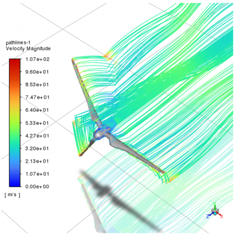
As the inlet velocity was increased to 70 m/s, the airflow velocity over the turbine blade rose significantly to 114 m/s (Figure 7(b)). In this case, the streamlines were observed to extend further downstream, suggesting a stronger and more energetic wake formation behind the blade. This indicated that higher inflow speeds enhanced momentum transfer across the blade surface, accelerating the airflow and extending its influence farther into the downstream flow field.
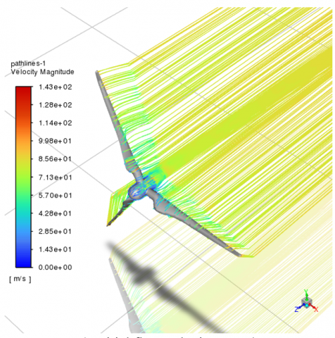
When the inlet wind speed was further increased to 90 m/s, the velocity of the airflow passing over the blade surface reached 143 m/s (Figure 7(c)). The streamlines were again observed to move extensively downstream, forming a longer and more developed wake. This behavior suggested that the kinetic energy imparted to the flow by the high inlet velocity and the blade’s rotation was significantly increased, resulting in a more pronounced aerodynamic response. The streamline elongation also indicated greater pressure differentials across the blade surface, which were typically associated with stronger lift generation—but also increased flow complexity and potential for unsteady aerodynamic phenomena.
These observations demonstrated that increasing the inlet wind speed had a direct and substantial influence on the flow field around the turbine blade. Not only was the airflow velocity amplified, but the streamline behavior also reflected the interaction between axial and tangential flow components induced by blade rotation. As airflow velocity rose, both aerodynamic loading and wake dynamics became more intense, potentially affecting overall turbine performance, stability, and downstream flow conditions. The findings also implied that under high inflow velocity conditions, the blade design must effectively manage both lift generation and flow separation risks to maintain optimal aerodynamic efficiency.
a) Initial flow velocity 50 m/s
b) Initial flow velocity 70 m/s
c) Initial flow velocity 90 m/s
Figure 7. Aerodynamic analysis results at different initial air flow velocity
The offshore wind turbine blade model was meshed automatically and was performed as follows: The physics preference was Mechanical, with element order set to Program Controlled. The default element size was 0.05 m. Sizing: Adaptive Sizing and Mesh Defeaturing were enabled to optimize the mesh based on the geometry. The resolution was set to Default (2), with a defeature size of 2.0e-002 m. The mesh uses Fast Transition for size change between elements. Geometric dimensions: The bounding box dimension was 135.95 m, the average surface area per element was 74.022 m², and the minimum edge length was 8.083e-003 m. Statistics: The meshing results achieved 28370 nodes and 15111 elements, ensuring a sufficient level of detail for structural analysis as depicted in Figure 8.
Figure 8. Finite element model
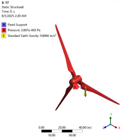
Figure 9. Set up loads and boundary conditions
In this static structural analysis, the model of a wind turbine blade assembly as presented in Figure 9 subjected to specific boundary conditions and loading. A fixed support was applied at the hub of the blade, fully constraining all degrees of freedom to simulate the connection to the main shaft. The blades were exposed to a pressure load of 2.897 × 10⁻³ Pa acting on their surface, representing aerodynamic effects. Additionally, standard Earth gravity with an acceleration of 9.8066 m/s² was applied in the negative Y-direction to account for the self-weight of the structure. These conditions aim to evaluate the structural response of the blades under combined aerodynamic and gravitational forces.
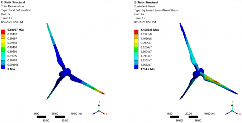
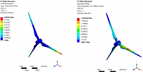
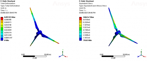
A redistribution of aerodynamic loading was observed as the blade pitch angle was increased from 8° to 12°, while the rotor speed was maintained at 15 revolutions per minute. This change in blade orientation resulted in noticeable variations in both mechanical deformation and equivalent stress, as illustrated in Figure 10. Specifically, the deformation changed slightly from 88.185 mm to 86.642 mm, while the equivalent stress decreased from 151.6 MPa to 146.41 MPa. These variations indicated that although the aerodynamic force distribution shifted with the increased pitch angle, the structural response of the blade remained within a relatively stable range.
Deformation was primarily concentrated from the mid-span to the trailing edge of the blade, while stress was consistently focused around the central region. This stress concentration suggested that, under critical loading scenarios, structural failure would most likely be initiated near the mid-blade section. The consistent location of both peak deformation and stress pointed to a structural weak point that would require reinforcement or careful monitoring during long-term operation.
a) Pitch angle = 8°
b) Pitch angle = 10°
c) Pitch angle = 12°
Figure 10. Results of offshore wind turbine blade durability analysis at different pitch angles
Despite the high inflow wind velocity of 55 m/s used in the simulation, the maximum stress observed 152.6 MPa remained below the material’s yield strength. This confirmed that the turbine blade maintained sufficient structural integrity under the tested conditions. No material failure was predicted, and the blade was deemed structurally sound under high aerodynamic loads.
These findings demonstrated that variations in blade pitch angle significantly influenced the aerodynamic load distribution, which in turn affected mechanical performance. However, the structural design of the blade was shown to be robust enough to accommodate the resulting stress and deformation. While the aerodynamic behavior became more complex with increased pitch, and localized mechanical responses were amplified, the overall integrity of the blade was preserved. Consequently, the turbine blade was considered to be both structurally stable and mechanically durable under varying pitch angles and high-speed wind conditions, though potential fatigue risks at stress concentration zones may require long-term evaluation.
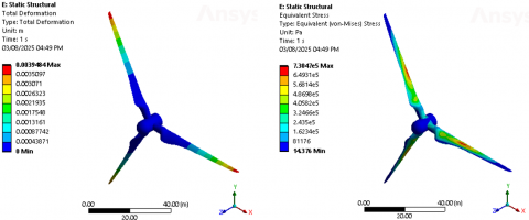
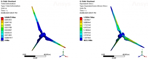
A redistribution of aerodynamic loading was observed as a result of increasing the initial airflow velocity from 50 m/s to 90 m/s, while maintaining the rotor speed at 15 revolutions per minute. This change in operating conditions led to a notable rise in mechanical responses, as evidenced by an increase in blade deformation from 0.39 mm to 6.06 mm, and in equivalent stress from 0.73 MPa to 11.583 MPa. These results, illustrated in Figure 11, indicated that both the structural integrity and service life of the turbine blade were significantly influenced by elevated airflow velocities.
a) Initial flow velocity 50 m/s
b) Initial flow velocity 70 m/s
c) Initial flow velocity 90 m/s
Figure 11. Results of offshore wind turbine blade durability analysis at different initial air flow velocities
Deformation was primarily concentrated along the mid-span and trailing edge regions of the blade, where bending and torsional effects were most pronounced. Concurrently, stress concentration was observed in the central section of the blade, suggesting that, under extreme loading conditions, failure would most likely initiate at this location. The increase in stress and deformation reflected the heightened aerodynamic forces acting on the blade surfaces, which translated into larger mechanical loads and potential fatigue risks over prolonged operation.
When performing simulations with an inlet air velocity of 90 m/s, the maximum stress was measured to be 11.583 MPa. This value was recorded as lower than the yield limit of the material. This indicates that the turbine blade structure ensures very good mechanical strength under the impact conditions of the air flow. This analysis result proves that the offshore wind turbine blade structure ensures durability against storms without breaking the offshore wind turbine blades.
The mechanical strength of the offshore wind turbine blades has been confirmed to be guaranteed against storms. Regardless of the initial air velocity, the designed turbine blades were guaranteed to be durable without being damaged. The stress and deformation increase as the inlet air velocity increases. The design structure not only ensures aerodynamic stability, stable lift of the blades, and high power output, but also ensures durability. In addition, the analysis results have shown that design factors have a significant influence on the aerodynamic behavior of offshore wind turbine blades and the power of the turbine blades. Therefore, optimization of these parameters is necessary to be carried out.
The simulation results obtained in this study were compared with findings from four previously published experimental investigations to assess the accuracy and reliability of the numerical model. In the study of Noever-Castelos et al. [31], full-scale blade deflection tests were conducted, and the measured deformation patterns were found to be consistent with those predicted by the present simulations, confirming the model’s capability to capture bending and twisting behaviors. Similarly, Chen et al. [32] performed static load experiments on a composite blade, and their progressive failure simulations aligned well with the deformation trends observed in this research. Aerodynamic performance benchmarks using NREL Phase VI data provided validation for the CFD results, as the lift and drag coefficients computed here were in good agreement with their reported values [33]. Additionally, vibration tests on 3D-printed blades conducted by Esquivel-Sancho et al. [34] yielded natural frequencies comparable to those predicted by the finite element analysis in this work. Although exact numerical values of wind speeds, deformations, and stresses were not always explicitly reported in the referenced studies, the qualitative agreement in response patterns reinforces the validity of the present modeling approach.
It was demonstrated that both the inlet airflow velocity and blade pitch angle critically influenced the aerodynamic behavior and structural responses of the offshore wind turbine blade. Importantly, the redistribution of aerodynamic forces caused by pitch angle adjustments was found to reduce stress concentrations, suggesting that optimized wind turbine blade angles can be strategically applied to enhance structural durability while maintaining aerodynamic efficiency.
Stress concentrations were consistently observed at the mid-span region, indicating that targeted reinforcement or material enhancement in this area should be prioritized in future blade designs to prevent premature failure. Moreover, the substantial increase in mechanical loading at higher wind turbine blade speeds highlighted the necessity of defining operational limits and control strategies to mitigate fatigue risks.
These design insights emphasize the need for an integrated approach that balances aerodynamic optimization with structural integrity, guiding engineers to develop blades that were both efficient and resilient under varying offshore conditions. The methodologies and findings presented here provide a foundational framework for the continued advancement and refinement of offshore wind turbine blade design.
[1] Yang, Y., Wang, D., Zhang, H., Zha, R., Wu, G., Cai, C., Li, Q.A. (2025). Enhancing aerodynamic performance of horizontal axis wind turbine blade aerodynamic performance under rough wall condition using vortex generators. Journal of Marine Science and Engineering, 13(3): 397. https://doi.org/10.3390/jmse13030397
[2] Hermansen, S.M., Lund, E. (2024). Multi-material and thickness optimization of a wind turbine blade root section. Structural and Multidisciplinary Optimization, 67(7): 107. https://doi.org/10.1007/s00158-024-03811-0
[3] He, F., Zheng, X., Luo, W., Zhong, J., Huang, Y., Ye, A., Ma, H. (2025). Collaborative optimization of aerodynamics and wind turbine blades. Applied Sciences, 15(2): 834. https://doi.org/10.3390/app15020834
[4] Shen, Z., Gong, S., Xie, G., Lu, H., Guo, W. (2024). Investigation of the effect of critical structural parameters on the aerodynamic performance of the double darrieus vertical axis wind turbine. Energy, 290: 130156. https://doi.org/10.1016/j.energy.2023.130156
[5] Radi, J., Sierra-García, J.E., Santos, M., Armenta-Déu, C., Djebli, A. (2024). Metaheuristic optimization of wind turbine airfoils with maximum-thickness and angle-of-attack constraints. Energies, 17(24): 6440. https://doi.org/10.3390/en17246440
[6] Li, J., Dao, M. H., Le, Q.T. (2024). Data-driven modal parameterization for robust aerodynamic shape optimization of wind turbine blades. Renewable Energy, 224: 120115. https://doi.org/10.1016/j.renene.2024.120115
[7] Hamlaoui, M.N., Bouhelal, A., Smaili, A., Khelladi, S., Fellouah, H. (2024). An inverse CFD actuator disk method for aerodynamic design and performance optimization of Horizontal Axis Wind Turbine blades. Energy Conversion and Management, 316: 118818. https://doi.org/10.1016/j.enconman.2024.118818
[8] Firoozi, A.A., Hejazi, F., Firoozi, A.A. (2024). Advancing wind energy efficiency: A systematic review of aerodynamic optimization in wind turbine blade design. Energies, 17(12): 2919. https://doi.org/10.3390/en17122919
[9] Wang, H., Chen, B. (2023). Investigation on aerodynamic noise for leading edge erosion of wind turbine blade. Journal of Wind Engineering and Industrial Aerodynamics, 240: 105484. https://doi.org/10.1016/j.jweia.2023.105484
[10] Özkan, R., Genç, M.S. (2023). Aerodynamic design and optimization of a small-scale wind turbine blade using a novel artificial bee colony algorithm based on blade element momentum (ABC-BEM) theory. Energy Conversion and Management, 283: 116937. https://doi.org/10.1016/j.enconman.2023.116937
[11] Cai, C., Yang, Y., Jia, Y., Wu, G., Zhang, H., Yuan, F., Li, Q.A. (2023). Aerodynamic load evaluation of leading edge and trailing edge windward states of large-scale wind turbine blade under parked condition. Applied Energy, 350: 121744. https://doi.org/10.1016/j.apenergy.2023.121744
[12] Yirtici, O., Tuncer, I.H. (2021). Aerodynamic shape optimization of wind turbine blades for minimizing power production losses due to icing. Cold Regions Science and Technology, 185: 103250. https://doi.org/10.1016/j.coldregions.2021.103250
[13] Ma, Y., Chen, C., Fan, T., Lu, H., Fang, J. (2022). An innovative aerodynamic design methodology of wind turbine blade models for wind tunnel real-time hybrid tests based on genetic algorithm. Ocean Engineering, 257: 111724. https://doi.org/10.1016/j.oceaneng.2022.111724
[14] Yen, S.C., Liu, W.S., San, K.C., Wang, W.F. (2021). Design of wind-turbine blades for improving aerodynamic performance using hybrid blades. Ocean Engineering, 227: 108889. https://doi.org/10.1016/j.oceaneng.2021.108889
[15] Lalonde, E.R., Vischschraper, B., Bitsuamlak, G., Dai, K. (2021). Comparison of neural network types and architectures for generating a surrogate aerodynamic wind turbine blade model. Journal of Wind Engineering and Industrial Aerodynamics, 216: 104696. https://doi.org/10.1016/j.jweia.2021.104696
[16] Hermansen, S.M., Macquart, T., Lund, E. (2025). Gradient-based structural optimization of a wind turbine blade root section including high-cycle fatigue constraints. Engineering Optimization, 1-32. https://doi.org/10.1080/0305215x.2024.2428678
[17] Papadakis, N., Condaxakis, C. (2024). An experimental performance assessment of a passively controlled wind turbine blade concept: Part B—material oriented with glass-fiber-reinforced polymer. Energies, 17(13): 3286. https://doi.org/10.3390/en17133286
[18] Kim, H.J., Cho, J.R. (2024). Effects of graphene reinforcement on static bending, free vibration, and torsion of wind turbine blades. Materials, 17(13): 3332. https://doi.org/10.3390/ma17133332
[19] Han, Y., Lei, Z., Dong, Y., Wang, Q., Li, H., Feng, F. (2024). The icing characteristics of a 1.5 MW wind turbine blade and its influence on the blade mechanical properties. Coatings, 14(2): 242. https://doi.org/10.3390/coatings14020242
[20] Pender, K., Bacharoudis, K., Romoli, F., Greaves, P., Fuller, J. (2024). Feasibility of natural fibre usage for wind turbine blade components: A structural and environmental assessment. Sustainability, 16(13): 5533. https://doi.org/10.3390/su16135533
[21] Firoozi, A.A., Firoozi, A.A., Hejazi, F. (2024). Innovations in wind turbine blade engineering: exploring materials, sustainability, and market dynamics. Sustainability, 16(19): 8564. https://doi.org/10.3390/su16198564
[22] Revilla-Cuesta, V., Manso-Morato, J., Hurtado-Alonso, N., Skaf, M., Ortega-López, V. (2024). Mechanical and environmental advantages of the revaluation of raw-crushed wind-turbine blades as a concrete component. Journal of Building Engineering, 82: 108383. https://doi.org/10.1016/j.jobe.2023.108383
[23] Zou, L., Chen, A., Li, C., Yang, X., Sun, Y. (2024). DCW-YOLO: An improved method for surface damage detection of wind turbine blades. Applied Sciences, 14(19): 8763. https://doi.org/10.3390/app14198763
[24] Zabihi, A., Aghdasi, F., Ellouzi, C., Singh, N.K., Jha, R., Shen, C. (2024). Non-contact wind turbine blade crack detection using laser doppler vibrometers. Energies, 17(9): 2165. https://doi.org/10.3390/en17092165
[25] Memari, M., Shekaramiz, M., Masoum, M.A., Seibi, A.C. (2024). Data fusion and ensemble learning for advanced anomaly detection using multi-spectral RGB and thermal imaging of small wind turbine blades. Energies, 17(3): 673. https://doi.org/10.3390/en17030673
[26] Lee, H., Hwang, Y.M., Lee, J., Kim, N.W., Ko, S.K. (2024). A drone-driven X-ray image-based diagnosis of wind turbine blades for reliable operation of wind turbine. IEEE Access, 12: 56141-56158. https://doi.org/10.1109/access.2024.3388494
[27] Davis, M., Nazario Dejesus, E., Shekaramiz, M., Zander, J., Memari, M. (2024). Identification and localization of wind turbine blade faults using deep learning. Applied Sciences, 14(14): 6319. https://doi.org/10.3390/app14146319
[28] Altice, B., Nazario, E., Davis, M., Shekaramiz, M., Moon, T.K., Masoum, M.A. (2024). Anomaly detection on small wind turbine blades using deep learning algorithms. Energies, 17(5): 982. https://doi.org/10.3390/en17050982
[29] Zhang, Z., Li, J., Lei, Z., Zhu, Q., Cheng, J., Gao, S. (2024). Reinforcement learning-based particle swarm optimization for wind farm layout problems. Energy, 313: 134050. https://doi.org/10.1016/j.energy.2024.134050
[30] Koragappa, P., Verdin, P.G. (2024). Design and optimisation of a 20 MW offshore wind turbine blade. Ocean Engineering, 305: 117975. https://doi.org/10.1016/j.oceaneng.2024.117975
[31] Noever-Castelos, P., Haller, B., Balzani, C. (2021). Validation of a modelling methodology for wind turbine rotor blades based on a full scale blade test. Wind Energy Science, 7(1): 105-127. https://doi.org/10.5194/wes-7-105-2022
[32] Chen, X., Zhao, W., Zhao, X.L., Xu, J.Z. (2014). Failure test and finite element simulation of a large wind turbine composite blade under static loading. Energies, 7(4): 2274-2297. https://doi.org/10.3390/en7042274
[33] Qaissi, K., Elsayed, O., Faqir, M., Essadiqi, E. (2021). A validation study of the aerodynamic behaviour of a wind turbine: Three-dimensional rotational case. CFD Letters, 13(9): 1-12. https://doi.org/10.37934/cfdl.13.9.112
[34] Esquivel-Sancho, L.M., Tehrani, M.G., Muñoz-Arias, M., Askari, M. (2025). Fault diagnosis of 3D-printed scaled wind turbine blades. arXiv preprint arXiv:2505.06080. https://doi.org/10.48550/arXiv.2505.06080