Hussein A. Jasim*![]() | Akeel Abbas Mohammed
| Akeel Abbas Mohammed![]() | Malik N. Hawas
| Malik N. Hawas![]()
© 2025 The authors. This article is published by IIETA and is licensed under the CC BY 4.0 license (http://creativecommons.org/licenses/by/4.0/).
OPEN ACCESS
Improving heat transfer is fundamental to increasing thermal efficiency through optimum heat exchange rates. Many parameters can be investigated to achieve this purpose, like tilted angles, PR, Re and BR to enhance heat transfer rate. This simulation evaluates the effect of multi-V ribs on heat transfer and friction factor, especially under turbulent flow conditions with Reynold number ranging from 6846 to 11980. The implication of the Re, PR, and α on heat transfer performance was studied where PR = 2 and 1. Findings reveal that as the Reynolds number goes up, the Nusselt number (Nu) becomes higher, while the friction factor (f) is reduced. A diagonal tape boosted heat transfer, reaching a Nu/Nu₀ ratio of 1.19 at Re = 6846. The pitch ratio has also strongly affected heat transfer; when the pitch ratio decreased, the Nu increased, with a peak increment of Nu = 169.75 at a pitch ratio of 1 and α = 60°. A decrease in pitch ratio results in a corresponding rise in the friction factor, where the maximum value of f = 0.647 at a Re = 6846, α = 60° and a pitch ratio of 1. Increasing the tilted angle increases raise f and Nu at varying PR.
tilted angle, pitch ratio, multi-V ribs
Many types of thermal systems need an increase in heat transfer rates to save power. Varied mechanisms are used to improve thermal performance. The appropriate kind of heat transfer optimization method is selected in accordance with the desired level of increase, geometry, cost, and pressure drop. Using obstacles is one technique used to enhance heat transfer, and that kind can be applied in different mechanical applications like SAH, HVAC and heat exchanger [1]. Obstacles like baffles, ribs, or rough surfaces increase heat transfer by obstructing fluid flow and causing turbulent flow, which improves heat exchange [2, 3]. There are many parameters of design that affect the heat transfer rate, like pitch ratio, blockage ratio, and rib size [4]. Blockage ratio and pitch ratio have a large impact on heat transfer rate, where pitch ratio affects the heat transfer coefficient and friction factor. Nu increases with decreasing pitch ratio, and the friction factor increases too. Blockage ratio increment gives an increase in Nu and f [5].
Alfarawi et al. [6] studied empirically effect of ribs shapes on heat transfer were used semicircular, rectangular and hybrid ribs with pitch ratio varied from 6.6-53 and Re in range of 12500-86500. Findings show that the hybrid ribs have more efficiency as compared with other shapes and the highest improvement in heat transfer had got at 6.6 while for rectangular and semicircular ribs were at 13.3, Nusselt number enhancement ratio was obtained between 1.3 and 2.14.
Promvonge et al. [7] studied impact of 30° angle-finned tape on heat transfer and flow properties. Air was the working fluid, BR = 0.1-0.3, PR = 1, 2, 3, and Re was in the range of 4000-23000. Empirical results reveal that smaller pitch spacing and BR = 0.3 gives largest heat transfer and friction factor, but at PR = 1 and BR = 0.2 provide highest thermal performance where the highest TEF about 1.95 and Nu number ratio is getting closer to 4.5 at lowest Re. Friction factor tends to improve with raising the BR and shows the rapid increase when BR ≥ 0.2 also Nu rise with increasing with Re and BR.
Kumar et al. [8] conducted an experiential study on heat transfer and friction factor in a square duct that has and has no inserts where flow is turbulent, and heat flux is constant. Results reveal a 30% increase in the Nu as a result of a 15% increment in Re. Inserts provide more increases in the heat transfer coefficient and generally, both of Nu and Re improved greatly with inserts.
Nuntadusit et al. [9] studied the effect of putting cut baffles on heat transfer, which include the standard baffle that involves a rectangular zigzag cut and another triangular zigzag cut with two different angles of 45° and 90°. The pitching ranges from 4, 6, and 8. Re was 20000. Results reveal that rectangular baffle provide the height thermal performance in several of pitch distances. Triangle zigzag-cut with 90° produces better heat transfer compared with triangle 45° in several pitch distances.
Kaewkohkiat et al. [10] had tested the influence of V-ribbed tape, which was put diagonally in a square duct, and the tilted angle was 45°, on heat transfer and friction factor. Air is the working fluid, and Re is 4000–25000, BR = 0.1, 0.15, 0.2, and 0.25, and PR = 0.75 and 2. V-ribs produce a longitudinal vortex, and BR and PR have a large effect on the thermal performance and at lower values of PR. BR = 0.25 gives maximal heat transfer and friction factor, while maximum thermal performance is achieved at BR = 0.2, PR = 0.75, where the TEF value is around 1.88 at the lowest Re. Friction factor lowers when there is an increase in PR but with a fall in BR.
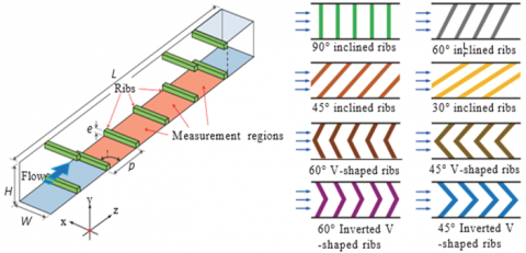
Kaewchoothong et al. [11] examined the impact of inclined ribs on the heat transfer coefficient in a square channel with different designs such as inclined, V-shaped, and inverted V-shaped, which has a square cross-section as shown in Figure 1. (e/Dh) ratio and pitch ratio were 0.133 and 10. Inclined ribs were α = 30°, 60°, and 90°, and other ribs were α = 45° and 60° with Re = 30000. Findings show that enhancement of the heat transfer coefficient for tilted ribs that have α = 60° and V-shaped ribs that have α = 45° and 60° offer more increment around 19.3%, 23.5%, and 32.6%, respectively, as compared with tilted ribs with α = 90°. V-ribs, which have α = 60°, achieve the largest average heat transfer as compared with others, and this is due to secondary flow, which is created by ribs.
Singh et al. [12] examined the effect of multi-V ribs on heat transfer by using perforated multi-V and continuous multi-V ribs where Re = 2000–18000, (e/Dh) is 0.043, (P/e) is 10, α is 60°, and W/w is 2–10. Results pointed out that perforation in multi-V ribs raises the thermal performance, where improvement in Nu for perforated multi-V ribs and multi-V ribs was 7.22 and 5.02 times as compared with the smooth case. Perforation has a large impact on the friction factor; it is decreased. Thermo-hydraulic performance was maximum where it reached 4.27 by using perforation multi-V rib. When W/w increases, Nu increases too, and it attains the maximal value at W/w = 6. Also, any extra increase in the W/w value reduces the Nu.
This simulation utilizes previous parameters mentioned that have a large effect on heat transfer enhancement and uses multi-V ribs to get the highest heat transfer rate and select optimal design parameters, then compares this design with 30°angle-finned tapes.
Figure 1. Variety of shapes of ribs placed at different angles
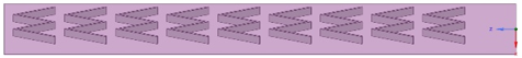
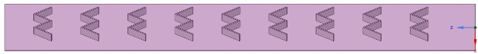
A square duct has a cross-section of 25 cm2 with a 50 cm length and has a 3 mm thickness. It has tape placed diagonally, and the thickness of the tape is 1 mm with 6.8 cm wide. Multi v-ribs are put on the upper and lower surfaces of tape with two angles ($\alpha$ = 30°, 60°) and available wide of multi-V ribs (w) was 4 cm as shown in Figure 2.
(a) 30°Multi V-ribs
(b) 60°Multi v-ribs
Figure 2. Upper surface of tape
The design parameters are shown in Table 1, The first upper rib is set 41.5 cm from the inlet, and the first lower rib is set 44 cm from the inlet.
Table 1. Design parameters
|
Parameter |
Value |
|
Height of duct (H) |
5 cm |
|
Length of duct and tape (L) |
50 cm |
|
Thickness of Duct |
0.3 cm |
|
Thickness of tape |
0.1 cm |
|
Relative roughness |
1.7 |
|
e |
1 cm |
|
PR |
1 and 2 |
|
α |
60° and 30° |
3.1 Governing equations
Duct simulations were evaluated as follows: Continuity equation, momentum equation, and energy equation [13].
$\frac{\partial}{\partial x_i}\left(\rho u_i\right)=0$ (1)
$\frac{\partial\left(\rho u_i u_i\right)}{\partial x_i}=-\frac{\partial P}{\partial x_i}+\frac{\partial}{\partial x_j}\left[\mu\left(\frac{\partial u_i}{\partial x_j}-\rho \dot{u_i} \dot{u}_j^{-}\right)\right]$ (2)
$\frac{\partial\left(\rho u_i \mathrm{~T}\right)}{\partial x_i}=\frac{\partial}{\partial x_j}\left[\left(\Gamma+\Gamma_t\right) \frac{\partial T}{\partial x_j}\right]$ (3)
$\Gamma=\frac{\mu}{p r}, \Gamma_t=\frac{\mu_t}{p r_t}$ (4)
Re, PR, Nu are investigated in this study [14]:
$R e=\frac{\rho u_i D_h}{\mu}$ (5)
$P R=\frac{p}{H}$ (6)
$N u=\frac{h * D_h}{k}$ (7)
3.2 Boundary conditions and solution methods
ANSYS FLUENT 20221 R2 was applied in this study and finite volume approach-based CFD software. Constant heat flux (1343 W/m2) was applied on the upper and lower surfaces of duct walls and other walls insulated by fiberglass with 0.01m insulation, no-slip boundary condition, and velocity of air varied 2-3.5 m/s. Flow is turbulent, and the k-ε (RNG model) with enhanced wall treatment is employed [15].
Assumptions of simulation were steady-state condition, 3D flow, density and fluid properties are constant, the outlet is exposed to atmospheric pressure and body force, radiation heat transfer and viscous dissipation are negligible [16].
The residual was set at an absolute criterion equal to 10-6, and solution methods include a scheme that was simple, a flux type that was distance-based, and momentum, pressure, and energy set in a second-order upwind [17]. The minimum number of iterations was 1200.
3.3 Mesh generation and validation
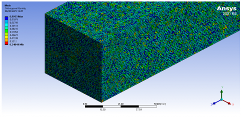
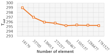
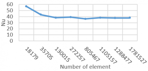
The tetrahedron method is used in the current simulation as shown in Figure 3 with respect to effect of number of elements up on Results different element is taken as shown in the Figure 4 and Figure 5. To get the best accurate mesh achieved at the number of elements was 1781527, and the mesh metric quality was good where skewness is 0.24708, orthogonal quality is 0.75194, and aspect ratio is 1.8783.
Figure 3. Three-dimensional mesh for a smooth duct
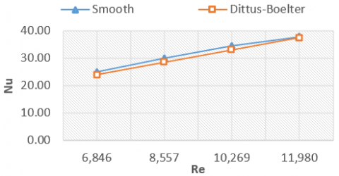
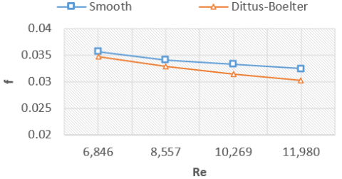
By contrasting the Nu and f calculated from the present simulation with those taken from the Dittus-Boelter Eq. (8) and Blasius correlations Eq. (9) [18] show that this simulation is acceptable, where the highest difference of Nu and f is less than +4% and +9% severally, as shown in Figure 6 and Figure 7.
$N u=0.023 R e^{0.8} P r^{0.4}$ For heating (8)
$f=0.316 R e^{-0.25}$ For $3000 \leq R e \leq 20,000$ (9)
Figure 4. Outlet temperature of air versus elements number
Figure 5. Nusselt number versus elements number
Figure 6. Nusselt number versus Re number
Figure 7. Friction factor versus Reynold number
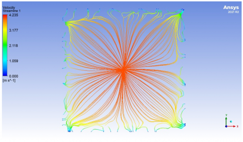
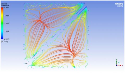
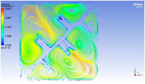
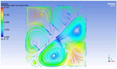
4.1 Flow structure
The flow structure in a square duct can be shown by streamline plots, as visualized in Figure 8. Figure 8 shows the vortexes' generation as a result of adding Multi-V ribs with angles of 60° and 30° across the length of the duct at a distance of 0.25 m. In a smooth and tape case, there are no vortexes, but multi-ribs with 60° and multi-V ribs angled 30° create six vortexes on each upper and lower surface of tape. Vortex flows can serve to improve heat transfer rates in the duct because of stronger fluid mixtures.
(a) Smooth duct
(b) Tape case
(c) Multi-V rib 30°
(d) Multi-V rib 60°
Figure 8. Velocity streamline for (a) smooth duct, (b) tape case, (c) multi-V rib 30°, (d) multi-V rib 60° at Re = 11980
4.2 Effect of design parameters
4.2.1 Effect of Re number
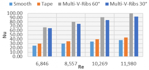
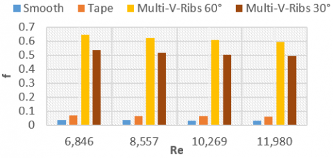
When the Re number increased, the Nu number increased too, and the friction factor decreased, as shown in Figure 9 and Figure 10. Inserting a diagonal tape in a square duct improves heat transfer where Nu/Nuo = 1.19 and f/f0 = 1.88 at the lowest Re number, as shown in Figure 11 and Figure 12.
Figure 9. Variation of Nusselt number with the Re number
Figure 10. Variation of friction factor with the Re number
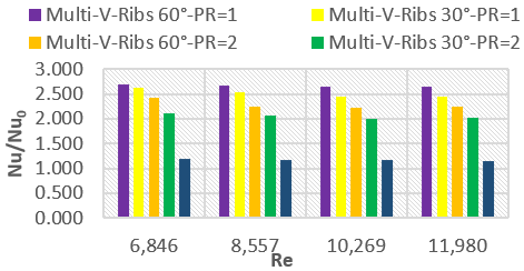
Figure 11. Variation of average Nusselt number with the Re number at different PR
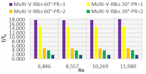
Figure 12. Variation of average friction factor with the Re number
4.2.2 Effect of pitch ratio
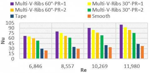
The influence of pitch ratio on heat transfer and friction factor was shown in Figures 13 and 14. In Figure 13, inserting multi-V ribs at α = 60° increases the heat transfer rate, and the Nu number gets higher as the pitch ratio is decreased, where the increment reaches 169.75% as compared with a smooth duct for Re = 6846 and PR = 1. At PR = 1, Re = 6846, and α = 60°, the Nu is higher by around 11.13% than at PR = 2. This is due to increasing levels of turbulence mixing and a greater vortex strength compared with PR = 2 [19].
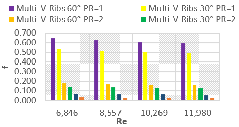
In Figure 14, the friction factor increases with decreasing the pitch ratio, where f = 0.647 at α = 60°, PR = 1, and Re = 6846, while at PR = 2, f = 0.177, therefore incrementing 265.54%. PR=1 provides the maximum value of Nu and f.
Figure 13. Variation of Nusselt number with different pitch ratio
Figure 14. Variation of friction factor with different pitch ratio
4.2.3 Effect of tilted angle
At PR = 2, the tilted angle has the same effect where the Nusselt number increases with increasing tilted angle but less than at PR = 1. At Re = 6846, the value of Nu = 60.63 at α = 60°, while the value of Nu = 52.92 at α = 30°. At PR = 1, Re = 6846, and α = 30°, the Nu is higher around 24% than at PR = 2. Optimal tilted angle and PR are 60° and 1, where enhancement of Nu is 169.752% compared with a smooth duct, while at α = 30°, enhancement of Nu is 162.89% compared with a smooth duct. In Figure 14, adding multi-V ribs at α = 30° increases the friction factor to 14.91 times more than a smooth duct at Re = 6846 and PR = 1, while 60° multi-V ribs provide more losses, which increase the friction factor to 17.93 times more than a smooth duct. At α = 60°, airflow faces more resistance and therefore more pressure drops. At PR = 2, the tilted angle has the same effect, where the friction factor increases with increasing tilted angle. This is due to an increasing resistance of airflow [20] but still less than PR = 1.
4.2.4 Performance evaluation
The average Nusselt number reduces as Re increases. As a PR gets lower, the average of Nu increases, where it reaches maximum at PR = 1. At PR = 1, α = 30°, and the lowest Re, the increment reaches 24.13% as compared with the PR = 2.
At PR = 1, α = 60°, and the lowest Re, the increment reaches 11.12% as compared with the PR = 2, as shown in Figure 10. The effect of tilted angle on average Nu is significant; the average Nu decreases with decreasing tilted angle, where at α = 60°, the increment reaches 14.59% as compared with α = 30°, PR = 2, and at the lowest Re.
The average friction factor starts decreasing and then increases as Re increases. As a PR gets lower, the average of f increases, where it reaches a maximum at PR = 1.
At PR = 1, α = 30°, increment reaches 277.89%, 278.62%, 280%, and 280.61% as compared with PR = 2 and depending on the Reynolds value.
At PR = 1, α = 60°, and the increment reaches 264.95%, 269.64%, 268.1%, and 269.12% as compared with PR 2 and depending on the Reynolds value, as shown in Figure 12.
60° multi-V ribs provide f/fo = 17.93-18.323 and Nu/Nuo = 2.7-2.67, and this is a considerable enhancement, which balances between heat transfer and pressure drop. comparing this design with other designs like 30° angle-finned tapes with BR = 0.3 and PR = 1 provide f/fo = 67-109 and Nu/Nuo = 5.9-6.3 [7].
A numerical study has been conducted to examine airflow characteristics that involve heat transfer and friction factor in a square duct set with diagonal tape with multi-V ribs at a varied pitch ratio and tilted angle for a turbulent flow. The following is concluded:
|
Dh |
hydraulic diameter, m |
|
e |
height of ribs, cm |
|
H k |
duct height, cm thermal conductivity, W.m-1. K-1 |
|
L |
length of Duct, cm |
|
P |
pressure, Kpa |
|
T |
temperature, K |
|
u |
velocity, m/s |
|
W |
width of tape, cm |
|
w |
width of single multi-v rib, cm |
|
x |
length of test section, cm |
|
$\Gamma$ |
thermal diffusivity |
|
Greek symbols |
|
|
a |
tilted angle, ° |
|
r |
density, kg/m3 |
|
µ |
dynamic viscosity, kg. m-1.s-1 |
|
Subscripts |
|
|
i |
inlet |
|
o |
smooth duct |
|
t |
turbulent |
|
Dimensionless parameters |
|
|
f |
friction factor |
|
f/f0 |
Average Friction factor |
|
Nu/Nuo |
Average Nusselt number |
|
Nu |
Nusselt number |
|
PR |
Pitch ratio |
|
Pr |
Prandtl number |
|
Re |
Reynold number |
|
TEF |
Thermal enhancement factor |
|
W/w |
Relative roughness width |
[1] Kareem, D.F., Mohammed, A.A., Al-Gburi, H. (2023). Empirical investigation of thermal features of phase change material as thermal storage system. Journal of Advanced Research in Fluid Mechanics and Thermal Sciences, 111(2): 154-169. https://doi.org/10.37934/arfmts.111.2.154169
[2] Wang, D., Liu, J., Liu, Y., Wang, Y., Li, B., Liu, J. (2020). Evaluation of the performance of an improved solar air heater with “S” shaped ribs with gap. Solar Energy, 195: 89-101. https://doi.org/10.1016/j.solener.2019.11.034
[3] Chamkha, A.J., Menni, Y. (2020). Hydrogen flow over a detached V-shaped rib in a rectangular channel. Mathematical Modelling of Engineering Problems, 7(2): 178-186. https://doi.org/10.18280/mmep.070202
[4] Sivakumar, K., Natarajan, E., Kulasekharan, N. (2014). Experimental studies on turbulent flow in ribbed rectangular convergent ducts with different rib sizes. International Journal of Heat and Technology, 32(1&2): 79-85.
[5] Yang, W.H., Xue, S.L., He, Y.H., Li, W. (2017). Experimental study on the heat transfer characteristics of high blockage ribs channel. Experimental Thermal and Fluid Science, 83: 248-259. https://doi.org/10.1016/j.expthermflusci.2017.01.016
[6] Alfarawi, S., Abdel-Moneim, S.A., Bodalal, A. (2017). Experimental investigations of heat transfer enhancement from rectangular duct roughened by hybrid ribs. International Journal of Thermal Sciences, 118: 123-138. https://doi.org/10.1016/j.ijthermalsci.2017.04.017
[7] Promvonge, P., Skullong, S., Kwankaomeng, S., Thiangpong, C. (2012). Heat transfer in square duct fitted diagonally with angle-finned tape—Part 1: Experimental study. International Communications in Heat and Mass Transfer, 39(5): 617-624. https://doi.org/10.1016/j.icheatmasstransfer.2012.03.007
[8] Kumar, M.U., Hussian, M.M., Ali, M.Y. (2013). Review of heat transfer enhancement techniques in square ducts with inserts. International Journal of Emerging Technology and Advanced Engineering, 3(8): 767-770.
[9] Nuntadusit, C., Piya, I., Wae-hayee, M., Eiamsa-ard, S. (2015). Heat transfer characteristics in a channel fitted with zigzag-cut baffles. Journal of Mechanical Science and Technology, 29(6): 2547-2554. https://doi.org/10.1007/s12206-015-0552-9
[10] Kaewkohkiat, Y.Y., Tamna, S., Promvonge, P. (2015). Enhanced heat transfer in square duct fitted diagonally with Double-Sided V-Ribbed Tapes. Applied Mechanics and Materials, 751: 251-256. https://doi.org/10.4028/www.scientific.net/AMM.751.251
[11] Kaewchoothong, N., Maliwan, K., Takeishi, K., Nuntadusit, C. (2017). Effect of inclined ribs on heat transfer coefficient in stationary square channel. Theoretical and Applied Mechanics Letters, 7(6): 344-350. https://doi.org/10.1016/j.taml.2017.09.013
[12] Singh, V.P., Jain, S., Gupta, J.M.L. (2023). Analysis of the effect of perforation in multi-v rib artificial roughened single pass solar air heater: - Part A. Experimental Heat Transfer, 36(2): 163-182. https://doi.org/10.1080/08916152.2021.1988761
[13] Sriromreuna, P., Sriromreunb, P. (2018). Numerical study on heat transfer enhancement in a rectangular duct with V-shaped ribs. Chemical Engineering, 70: 1285-1290. https://doi.org/10.3303/CET1870215
[14] Sriromreun, P. (2017). Numerical study on heat transfer enhancement in a rectangular duct with incline shaped baffles. Chemical Engineering Transactions, 57: 1243-1248. https://doi.org/10.3303/CET1757208
[15] Sahel, D., Ameur, H., Baki, T. (2020). Effect of the size of graded baffles on the performance of channel heat exchangers. Thermal Science, 24(2): 767-775. https://doi.org/10.2298/TSCI180326295S
[16] Gogoi, P., Triveni, M.K., Panua, R. (2017). Numerical investigation of 3D turbulent forced convective heat transfer and friction characteristics of a square duct. International Journal of Heat and Technology, 35(4): 919-932. https://doi.org/10.18280/ijht.350428
[17] Oleiwi, A., Mohsen, A.M., Abdulkadhim, A., Abed, A. M., Laidoudi, H., Abderrahmane, A. (2023). Experimental and numerical study on the heat transfer enhancement over scalene and curved‐side triangular ribs. Heat Transfer, 52(5): 3433-3452. https://doi.org/10.1002/htj.22835
[18] Noothong, W., Suwannapan, S., Thianpong, C., Promvonge, P. (2015). Enhanced heat transfer in a heat exchanger square-duct with discrete V-finned tape inserts. Chinese Journal of Chemical Engineering, 23(3): 490-498. https://doi.org/10.1016/j.cjche.2014.05.018
[19] Promvonge, P., Skullong, S., Kwankaomeng, S., Thiangpong, C. (2012). Heat transfer in square duct fitted diagonally with angle-finned tape—Part 1: Experimental study. International Communications in Heat and Mass Transfer, 39(5): 617-624. https://doi.org/10.1016/j.icheatmasstransfer.2012.03.007
[20] Albaldaw, R.A., Shyaa, A.K., Abd Al-Ameer, S. (2017). Experimental investigation for enhancement heat transfer in a channel with angle-ribbed tape at various attack angle. Journal of Engineering and Sustainable Development, 21(2): 163-180.