Sanaa Abourub![]() | Hakim Kbab*
| Hakim Kbab*![]() | Anis Tcherak
| Anis Tcherak![]() | Omar Abada
| Omar Abada![]()
© 2025 The authors. This article is published by IIETA and is licensed under the CC BY 4.0 license (http://creativecommons.org/licenses/by/4.0/).
OPEN ACCESS
Nozzle design is a key challenge in aerospace engineering, where the goal is to maximize performance under changing operating conditions. Dual-bell nozzles, valued for their altitude adaptability and potential mass reduction, are a promising solution. Most previous studies assessed their performance using cold gas models, valid only for stagnation temperatures below 1000 K. These models do not capture the thermodynamic conditions of real propulsion systems, where combustion chamber temperatures are often much higher. This study introduces a high-temperature gas model for air, applicable up to 5000 K (avoiding chemical dissociation). In this range, the specific heat at constant pressure (Cp) varies with temperature, requiring modifications to the energy equation and Prandtl–Meyer function. These changes affect both the nozzle design process and predictions of flow expansion at the inflection point. We present a new framework for predicting dual-bell nozzle performance using real-gas thermodynamics. A comparison with the perfect gas model quantifies the impact of thermal effects on geometry and performance. Numerical simulations further show how high temperatures influence the transition between sea-level and altitude operating modes. Results indicate that accounting for real-gas effects leads to a higher expansion ratio, improved thrust performance, and an increased nozzle pressure ratio at transition.
supersonic nozzles, characteristics method, dual bell nozzle, supersonic flow, high temperatures
The concept of dual-bell nozzles was proposed by Foster and Cowles [1] as an advancement in the field of space propulsion. These nozzles are designed to automatically adapt to altitude variations without requiring mechanical activation, thereby reducing their weight. Their goal was to meet the rapid development of space propulsion and the increasing performance demands of that era.
The first experimental and numerical studies were conducted in the 1990s by Horn and Fisher [2], Frey and Hagemann [3], and Immich and Caporicci [4], aiming to demonstrate the feasibility of this new concept. These studies also predicted a payload increase of more than 70% if a dual-bell nozzle was used on the FSS1 engine. Miyazawa et al. [5] calculated an increase in specific impulse of 10 seconds in their study.
Early experimental and analytical studies by Hagemann et al. [6] provided foundational verification of the dual-bell principle, demonstrating its capability to extend performance beyond conventional bell nozzles by enabling controlled flow separation and transition. These pioneering investigations established the feasibility of the concept and motivated subsequent numerical and experimental research.
In addition to flow physics, researchers have explored design optimization approaches to improve nozzle efficiency. Tcherak et al. [7] proposed a novel axisymmetric dual-bell nozzle configuration, reporting enhanced performance potential over traditional geometries.
A significant body of work has focused on the understanding of flow transition mechanisms in dual-bell nozzles. Nürnberger-Genin and Stark [8] investigated the transition between sea-level and altitude modes, emphasizing the role of pressure gradients and separation shock dynamics. Their studies provided valuable insights into the hysteresis effects associated with mode switching, which remain a key challenge in ensuring predictable nozzle performance. Loosen et al. [9] extended this line of research through high-fidelity numerical simulations, analyzing jet–wake interactions that govern separation behavior in the dual-bell configuration. Similarly, Scharnowski and Kähler [10] examined the base flow of a generic launcher equipped with a dual-bell nozzle, highlighting the influence of nozzle geometry on the stability of the separated flow region. Collectively, these works underscore the complexity of flow transition phenomena and the importance of coupling experimental validation with advanced computational modeling.
The previous study [8] applied artificial neural network (ANN) algorithms for design optimization and computational validation, demonstrating the growing trend of integrating machine learning with computational fluid dynamics (CFD) tools to accelerate the design process. These contributions reflect a shift from purely physics-based studies toward data-driven optimization strategies in nozzle research.
The development of advanced simulation techniques has further enriched dual-bell nozzle analysis. Scarlatella et al. [11] employed Reynolds-averaged Navier–Stokes (RANS) simulations to assess nozzle performance under retro-flow conditions relevant to vertical landing operations of reusable launch vehicles. Their results not only reinforced the adaptability of dual-bell nozzles for modern space transportation but also addressed operational aspects associated with reusability. Toufik et al. [12] investigated the influence of the extension angle on the transition between the nozzle's two operating modes. The evolution of parameters was analyzed and studied by Kbab et al. [13]. In 2017, the same authors, Kbab et al. [14], proposed a TOP profile for the base nozzle design for the first time, yielding satisfactory results.
In 2023, several studies explored the performance of dual-bell nozzles from various perspectives. Liu and Li [15] analyzed the impact of aspiration drag at low altitudes and investigated how design parameters influence this drag at different flight altitudes using simulations. In their study, Wu et al. [16] numerically investigated the flow in a dual-bell nozzle, validating CFD results with experimental data. They analyzed wall pressure distributions and hysteresis behavior near the nozzle inflection point across a wide nozzle pressure ratio (NPR) range (6–55). Their findings confirmed the transition dynamics between sea-level and high-altitude operating modes.
In 2022, Ferrero et al. [17] conducted a study on transition control using fluidic injection. In 2024, Patil et al. [18] investigated the altitude-adaptation mechanisms of dual-bell nozzles (DBNs) through ANSYS-based CFD simulations of a two-dimensional axisymmetric model. Using a control volume approach, they analyzed Mach number, pressure, and temperature distributions, demonstrating that higher aspect ratios significantly enhance high-altitude performance via optimized Prandtl–Meyer expansion at the inflection point. Their results quantitatively established the relationship between nozzle geometry and altitude-dependent flow patterns, providing key insights for DBN design optimization.
In recent years, ONERA has emerged as a leader in the field of dual-bell nozzles, focusing on fluidic injection and transition control in this type of nozzle, experimenting with multiple injection gases in the process [19-22].
During 2025, several research efforts were undertaken to further advance the understanding and optimization of dual-bell nozzles (DBNs), with a focus on improving flow control, thermal management, and overall propulsive efficiency across varying altitudes. Building on the need for precise mode transition control, Legros et al. [23] investigated DBN flow regulation using transverse secondary injection through steady-state CFD simulations. While baseline simulations without injection reproduced the main flow structures, the predicted separation location near the transition NPR was inaccurate until turbulence model calibration was performed via structural parameter adjustment.
Introducing secondary injection enabled the simulations to match experimental observations of increased transition NPR with higher mass flow rates, although limitations persisted near critical NPR values due to insufficient interaction between the separation and inflection zones, as evidenced by wall-pressure measurements and Schlieren imaging. In another investigation, Raju et al. [24] examined thermal management strategies by numerically studying a DBN equipped with hydrogen film cooling in an LO₂/LH₂ engine, using two-dimensional axisymmetric CFD simulations. Their validated model (RMSD = 0.0012) revealed substantial shifts in the separation point (up to 1.34× at NPR = 30) and highlighted marked differences in cooling effectiveness between propellants (0.78 for LH₂ vs. 0.27 for RP-1), albeit with a 3–5% penalty in specific impulse. This systematic analysis across a broad NPR range provided important insights into the trade-offs between cooling performance and propulsive efficiency in altitude-adaptive nozzle designs.
Focusing on geometric optimization, Chehat et al. [25] aimed to reduce performance losses and side loads while enhancing adaptability to different altitudes. Their study compared three baseline configurations—TIC, TOP, and MNL—combined with a constant-pressure extension, using CFD simulations validated against experimental data. The evaluation encompassed geometric parameters, flow dynamics, mode transition behavior, and performance metrics such as thrust, specific impulse, and aspiration drag over a wide NPR spectrum. Among the tested designs, the TOP configuration exhibited the most favorable performance, characterized by faster transitions, higher propulsive efficiency, and a significant reduction in aspiration drag, particularly in high-altitude operation, thus establishing it as the most promising option for future aerospace propulsion applications.
After this comprehensive literature review on dual-bell nozzles, it has been observed that all the works published in this field are based on the use of the perfect gas model with constant specific heat capacity (CP). However, this assumption does not account for the actual behavior of the gas when the temperature exceeds 1000 K. Under these conditions, it is necessary to completely reconsider the mathematical model used. The new model, termed the high-temperature perfect gas model, primarily differs in the energy equation and the Prandtl-Meyer equation. By replacing the energy equation with a new equation that considers the variation of specific heats at high temperatures, we obtain a new model to solve. The resolution philosophy remains essentially the same, with some minor modifications. Generally, choosing two state variables is sufficient to determine the other parameters. In our study, we propose for the first time a computational approach for flows in high-temperature dual-bell nozzles. We will examine the effect of high temperature on design, parameter evolution, and performance, and compare these results to those obtained for a perfect gas. Finally, we will analyze the influence of high temperature on flow transition.
2.1 Hypotheses and mathematical formulation
The resolution of the problem of flow in supersonic nozzles involves simultaneously solving the equations of conservation of mass, axial and radial momentum, and energy. In this regard, the following assumptions are considered:
The mathematical formulation of the problem is as follows:
$\frac{\partial(\rho u)}{\partial x}+\frac{1}{y^\delta} \frac{\partial\left(y^\delta \rho v\right)}{\partial y}=0$ (1)
$\frac{\partial\left(\rho u^2+P\right)}{\partial x}+\frac{\partial(\rho u v)}{\partial y}=0$ (2)
$\frac{\partial(\rho u v)}{\partial x}+\frac{\partial\left(\rho v^2+P\right)}{\partial y}=0$ (3)
$V^2=2 H(T)$ (4)
With
$H(T)=\int_T^{T_0} C_P(T) d T$ (5)
And
$V^2=u^2+v^2$ (6)
$a^2(T)=\gamma(T) R T$ (7)
$P=\rho R T$ (8)
The development of thermodynamic relations is based on the use of conservation equations in differential form:
$a^2=\left(\frac{d P}{d \rho}\right)_{s=\text { constant }}$ (9)
After performing mathematical transformations, we arrive at the following result:
$a^2(T)=\gamma(T) R T$ (10)
The energy conservation equation in differential form is written as:
$C_p d T+V d V=0$ (11)
Integrating Eq. (11) between the initial reference state, which is the combustion chamber for our study (V0 ≈ 0, T0), and any arbitrary state given by (V, T), we obtain:
$\int_{V_0}^V V d V=-\int_{T_0}^T C_P(T) d T$ (12)
At the exit of the combustion chamber, where V0 ≈ 0 and T0 is given, we can find the velocity at a supersonic point using the following relation:
$V^2=-2 \int_{T_0}^T C_P(T) d T$ (13)
With
$H(T)=\int_T^{T_0} C_P(T) d T$ (14)
Thus
$V^2=2 H(T)$ (15)
Combining Eqs. (10) and (15), we obtain:
$M=\frac{v}{a}$ (16)
Thus
$M(T)=\frac{\sqrt{2 H(T)}}{a(T)}$ (17)
Eq. (17) shows the variation of Mach number as a function of temperature for a calorically imperfect gas.
The momentum conservation equation in differential form is written as:
$V d V+\frac{d P}{\rho}=0$ (18)
By representing the Mach number, substituting Eq. (16), and then substituting Eqs. (17) and (18), we obtain:
$\frac{d \rho}{\rho}=F_\rho(T) d T$ (19)
With
$F_\rho(T)=\frac{C_P(T)}{a^2(T)}$ (20)
The ratio of the densities corresponding to temperature T can be obtained by integrating Eq. (19) between the reference state (ρ0, T0) and the given state (ρ, T). These yield:
$\frac{\rho}{\rho_0}=\operatorname{Exp}\left(-\int_T^{T_0} F_\rho(T) d T\right)$ (21)
The pressure ratio is given using the following relation (Eq. (22)) once the ratios of densities and temperatures are known.
$\frac{P}{P_0}=\left(\frac{\rho}{\rho_0}\right)\left(\frac{T}{T_0}\right)$ (22)
The mass conservation equation is given by:
$\rho V A=$ constant (23)
The differential form of the Eq. (23) is:
$\frac{d A}{A}=F_A(T) d T$ (24)
With
$F_A(T)=C_P(T)\left[\frac{1}{a^2(T)}-\frac{1}{2 H(T)}\right]$ (25)
Integrating Eq. (24) between the throat state (A*, T*) and any state (A, T) in the divergent section determines the ratio of supersonic cross-sectional areas:
$\frac{A}{A_*}=\operatorname{Exp}\left(-\int_T^{T_*} F_A(T) d T\right)$ (26)
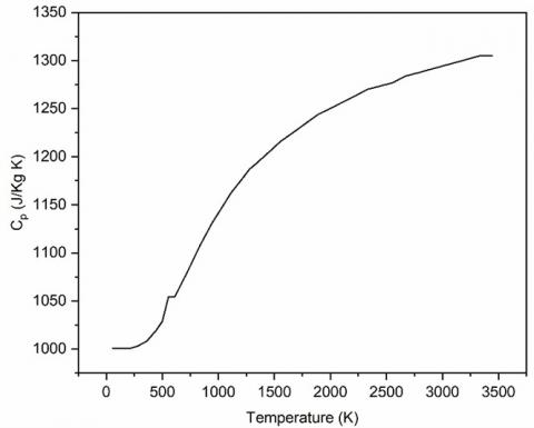
We notice that to calculate the parameters ρ and A, we need to compute the integral of a certain function where analytical procedures are impractical due to the complexity of the functions involved. Therefore, our focus turns towards numerical computation. The bisection method is used for solving the nonlinear algebraic equations encountered, and the Simpson's algorithm is used for numerical integration of the presented functions. All parameters M, ρ, and A are functions of temperature. The specific heat at constant pressure, Cp(T) is a function of temperature and is given by the following 9th degree polynomial expression:
$\begin{gathered}C_p(T)=\alpha_0+\alpha_1 T+\alpha_2 T^2+\alpha_3 T^3+\alpha_4 T^4+ \\ \alpha_5 T^5+\alpha_6 T^6+\alpha_7 T^7+\alpha_8 T^8+\alpha_9 T^9\end{gathered}$ (27)
The least-squares interpolation method is used to calculates the coefficients αi (Table 1) based on the data given in Table 2 for air.
Table 1. Coefficients of the 9th degree polynomial Cp(T)
|
$\alpha_0$ |
1001.1058 |
|
$\alpha_1$ |
0.040661289 |
|
$\alpha_2$ |
-0.00063376997 |
|
$\alpha_3$ |
2.7474759×10-06 |
|
$\alpha_4$ |
-4.0338459×10-09 |
|
$\alpha_5$ |
3.0697736×10⁻¹² |
|
$\alpha_6$ |
-1.3509355×10⁻¹⁵ |
|
$\alpha_7$ |
3.472262×10⁻¹⁹ |
|
$\alpha_8$ |
-4.8467531×10⁻²³ |
|
$\alpha_9$ |
2.8411878×10⁻²⁷ |
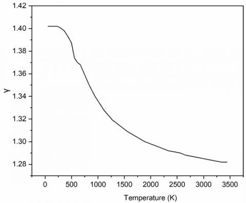
The variations of CP(T) and γ(T) versus the temperature for air are illustrated in Figure 1 and Figure 2.
2.2 Prandtl-Meyer function
The resolution of the problem of flow in supersonic nozzles involves simultaneously solving the equations of conservation of mass, axial and radial momentum, and energy. In this regard, the following assumptions are considered:
The Prandtl-Meyer function plays a crucial role in the calculation of supersonic flows. If one wishes to design a supersonic nozzle that provides a uniform and parallel flow at the exit section, it is essential to determine the initial expansion angle at the throat to achieve the desired Mach number at the exit. The design of such nozzles is based on the application of the method of characteristics (MoC), which is formulated using the Prandtl-Meyer function.
Figure 1. Variation of specific heat CP(T) versus the temperature for air
Figure 2. Variation of specific heat ratio γ(T) versus the temperature for air
Table 2. Variation of CP(T) and γ(T) versus the temperature for air
|
T(K) |
Cp (J/Kg K) |
γ(T) |
T(K) |
Cp (J/Kg K) |
γ(T) |
T(K) |
Cp (J/Kg K) |
γ(T) |
|
55,538 |
1001,104 |
1,402 |
833,316 |
1107,192 |
1,35 |
1999,983 |
1250,305 |
1,298 |
|
222,205 |
1001,101 |
1,402 |
888,872 |
1119,078 |
1,345 |
2111,094 |
1256,813 |
1,296 |
|
277,761 |
1002,885 |
1,401 |
944,427 |
1131,314 |
1,34 |
2222,205 |
1263,410 |
1,294 |
|
305,538 |
1004,675 |
1,4 |
999,983 |
1141,365 |
1,336 |
2333,316 |
1270,097 |
1,292 |
|
333,316 |
1006,473 |
1,399 |
1055,538 |
1151,658 |
1,332 |
2444,427 |
1273,476 |
1,291 |
|
361,094 |
1008,281 |
1,398 |
1111,094 |
1162,202 |
1,328 |
2555,538 |
1276,877 |
1,290 |
|
388,872 |
1011,923 |
1,396 |
1166,650 |
1170,280 |
1,325 |
2666,650 |
1283,751 |
1,288 |
|
416,65 |
1015,603 |
1,394 |
1222,205 |
1178,509 |
1,322 |
2777,761 |
1287,224 |
1,287 |
|
444,427 |
1019,32 |
1,392 |
1277,761 |
1186,893 |
1,319 |
2888,872 |
1290,721 |
1,286 |
|
499,983 |
1028,781 |
1,387 |
1333,316 |
1192,570 |
1,317 |
2999,983 |
1294,242 |
1,285 |
|
555,538 |
1054,563 |
1,374 |
1444,427 |
1204,142 |
1,313 |
3111,094 |
1297,789 |
1,284 |
|
611,094 |
1054,563 |
1,37 |
1555,538 |
1216,014 |
1,309 |
3222,205 |
1301,360 |
1,283 |
|
666,65 |
1067,077 |
1,368 |
1666,650 |
1225,121 |
1,306 |
3333,316 |
1304,957 |
1,282 |
|
722,205 |
1080,005 |
1,362 |
1777,761 |
1234,409 |
1,303 |
3444,427 |
1304,957 |
1,282 |
|
777,761 |
1093,37 |
1,356 |
1888,872 |
1243,883 |
1,300 |
3444,427 |
1304,957 |
1,282 |
The function ν is defined purely in the supersonic regime. When M = 1.0, ν = 0.0 is set, as calculation proceeds via definite integration. Thus, the function ν represents the deviation of the flow velocity vector corresponding to Mach number M > 1.00 from the velocity vector at M = 1.00. The value of ν for a supersonic Mach number M > 1.0 (where the temperature is lower than the critical temperature, T < T*) is given by:
$v=\int_T^{T_*} F_v(T) d T$ (28)
With
$F_v(T)=\frac{C_P(T)}{2 H(T)} \sqrt{\frac{2 H(T)}{a^2(T)}-1}$ (29)
It is noted that calculating the value of ν requires integrating function (29), where analytical procedures are impractical due to the complexity of this function to integrate. Therefore, our focus turns towards numerical computation using the Simpson method. The system consists of five equations with five unknowns (ρ, u, v, P, T). After performing mathematical transformations, we obtain a single equation relating the components of the velocity vector, presented by the following relationship. For axisymmetric flow, symmetry is along the x-axis. The y-direction in the equations corresponds to the radial direction.
$\begin{gathered}\left(a^2-u^2\right) \frac{\partial u}{\partial x}+\left(a^2-v^2\right) \frac{\partial v}{\partial y}-u v\left[\frac{\partial v}{\partial x}+\frac{\partial u}{\partial y}\right]+\delta a^2 \frac{v}{y} =0\end{gathered}$ (30)
The parameter δ distinguishes between different flow configurations: δ = 0 corresponds to planar flow, while δ = 1 describes axisymmetric flow. Thus, we obtain the general equation of gas dynamics. The speed of sound is a function of temperature according to the energy equation. Since the flow is isentropic, the condition ∇⋅(ρV) = 0 is expressed as:
$\frac{\partial v}{\partial x}-\frac{\partial u}{\partial y}=0$ (31)
These equations transform into hyperbolic form, where their solution at a given point depends entirely on upstream conditions and numerical methods like the 'step-by-step" approach, such as the method of characteristics.
In such scenarios, these equations demonstrate characteristic directions in the (x, y) plane where the normal derivative of dependent variables (in this case, u and v) can be discontinuous, while the velocity must remain continuous. Along these characteristic directions, the dependent variables must satisfy the compatibility equation, which plays a central role in the method of characteristics. Substituting Eqs. (31) and (32) into Eq. (30) results in the compatibility equation as follows:
$\sigma_1\left(u^2-\mathrm{a}^2\right) \frac{d u}{d x}+\left(-\sigma_2\right) \frac{d v}{d x}-\sigma_1 \frac{\delta \mathrm{a}^2 v}{y}=0 c$ (32)
Multiplying the compatibility equation above by (dx), we obtain:
$\sigma_1\left(u^2-\mathrm{a}^2\right) d u-\sigma_2 d v-\sigma_1 \frac{\delta \mathrm{a}^2 v}{y} d x=0$ (33)
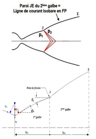
Figure 3. Expansion centered at junction point J
Eq. (33) of compatibility provides two differential equations linking the velocity components ν. These are valid only along the characteristics C- and C+.
The profile of the second curve is calculated for a constant wall pressure P2. Under the assumption of inviscid flow, this profile coincides with the isobaric streamline of the perfect fluid with pressure P2. This streamline is obtained using the direct method of characteristics. It is applied for an expansion wave (Prandtl-Meyer wave) of intensity P2/P1 at junction point J, as shown in Figure 3. The profile of the second curve is calculated for a constant wall pressure P2. Under the assumption of inviscid flow, this profile coincides with the isobaric streamline of the perfect fluid with pressure P2. This streamline is obtained using the direct method of characteristics. It is applied for an expansion wave (Prandtl-Meyer wave) of intensity P2/P1 at junction point J, as shown in Figure 3.
3.1 DBN nozzle design
To design the nozzle and assess its performance, an in-house method of characteristics (MoC) code was developed in the Fortran language. The program requires geometric and thermodynamic input parameters. The stagnation pressure at the combustion chamber exit, P0, is set to 30 bar. The stagnation temperature, T0, is set to 243 K for the perfect gas case (nozzle 1, N1), and to 1000 K, 2000 K, and 3000 K for the high-temperature cases corresponding to nozzle 2 (N2), nozzle 3 (N3), and nozzle 4 (N4), respectively. The upstream and downstream curvature radii are identical, each having a value of 0.03. The design Mach numbers are 3.9 for the base nozzle and 4.1 at the exit of the complete nozzle. The base nozzle was designed as a truncated ideal contour (TIC), truncated at the junction point, yielding a Mach number of 3.4, in order to reduce structural mass, while the extension nozzle was designed using the constant pressure (CP) method.
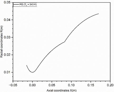
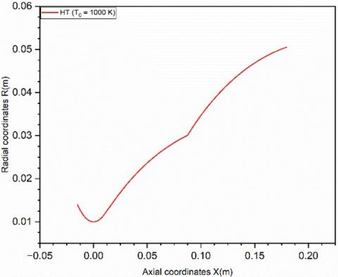
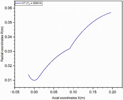
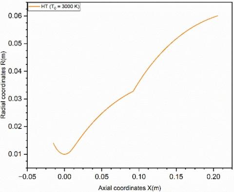
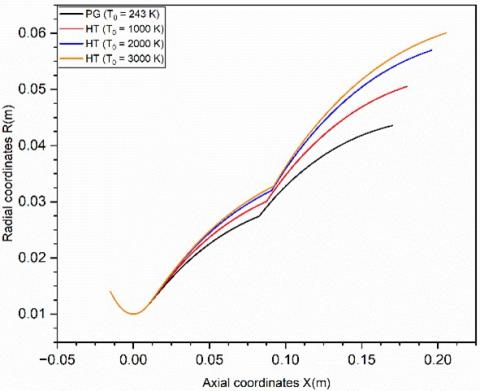
Figures 4-8 present a comparison of the nozzle profiles obtained for the perfect gas case and for the high-temperature cases at 1000 K, 2000 K, and 3000 K. It is evident that temperature has a significant influence on the nozzle geometry: as the temperature increases, the nozzle becomes longer and the exit area enlarges. This behavior is attributed to the fact that hotter gases require more expansion volume, resulting in an extended nozzle contour. This increase in length and exit area is observed in both the base and extension sections of the nozzle.
Figure 4. Dual-bell nozzle contour: T0 = 243 K (Perfect gas model)
Figure 5. Dual-bell nozzle contour: T0 = 1000 K (High-Temperature gas model)
Table 3 summarizes the geometric data for each nozzle configuration. The parameters L1, L2, and L denote the lengths of the base nozzle, the extension, and the total nozzle length, respectively, expressed in meters. J indicates the coordinates of the junction point for each nozzle. S1 and S2 represent the cross-sectional areas of the base nozzle and the extension, respectively, while θ denotes the inflection angle of the extension for each nozzle. Notably, the N4 nozzle, corresponding to the highest temperature (3000 K), exhibits the greatest length and exit area, whereas the N1 nozzle, corresponding to the lowest temperature (243 K), has the shortest length and smallest exit area. Moreover, the inflection angle θ increases with increasing stagnation temperature, reflecting the greater divergence required to accommodate the higher thermal energy and resulting expansion of the exhaust gases.
Figure 6. Dual-bell nozzle contour: T0 = 2000 K (High-Temperature gas)
Figure 7. Dual-bell nozzle contour: T0 = 3000 K (High-Temperature gas model)
Table 3. DBN designs geometrical characteristics
|
DBN |
Length 1st Bell (m) |
Length 2nd Bell (m) |
Total Length (m) |
Inflection Angle (deg) |
|
N1: GP |
8.265866E-02 |
0.08745564 |
1.701143E-01 |
10.448874440054 |
|
N2: 1000 |
8.751992E-02 |
0.09237168 |
1.798916E-01 |
12.496896999232 |
|
N3: 2000 |
9.092478E-02 |
0.10499092 |
1.959157E-01 |
13.37034639982 |
|
N4: 3000 |
9.220724E-02 |
0.11335266 |
2.055599E-01 |
13.537288092432 |
|
DBN |
Throat Area Section (m2) AThroat (Rthroat = 0.01 m) |
Junction Point (J) Coordinates |
1st Bell Exit Area Section (A=π×R2) Afirst bell (m2) |
2nd Bell Exit Area Section Asecond bell (m2) |
|
N1: GP |
0.0003141593 |
XJ = 8.265866E-02 m RJ = 2.742179E-02 m |
0.002362334943 |
0.00595836069 |
|
N2: 1000 |
0.0003141593 |
XJ = 8.751992E-02 m RJ = 3.006013E-02 m |
0.002838778985 |
0.008022381341 |
|
N3: 2000 |
0.0003141593 |
XJ = 9.092478E-02 m RJ = 3.200971E-02 m |
0.003218943485 |
0.01019438173 |
|
N4: 3000 |
0.0003141593 |
XJ = 9.220724E-02 m RJ = 3.276133E-02 m |
0.003371886297 |
0.01132969649 |
Figure 8. Dual-bell nozzle contours comparison
3.2 Influence of the temperature-dependent Prandtl–Meyer function on dual-bell nozzle design
In the design of supersonic nozzles using the method of characteristics (MoC), the Prandtl–Meyer (PM) function, denoted ν(M, γ), plays a central role in defining flow expansion and wall contour generation. Under the perfect gas (PG) assumption, the PM function is expressed as:
$\begin{gathered}v(M)=\sqrt{\frac{\gamma+1}{\gamma-1}} \cdot \tan ^{-1}\left(\sqrt{\frac{\gamma-1}{\gamma+1}\left(M^2-1\right)}\right)- \tan ^{-1}\left(\sqrt{M^2-1}\right)\end{gathered}$ (34)
However, this formulation assumes a constant specific heat ratio γ. At high temperatures, particularly above 1000 K, this assumption becomes invalid due to the temperature dependence of specific heats (Cp(T)) and hence of γ(T) = Cp(T)/Cv(T). As a result, the PM function becomes a function of both Mach number and temperature:
$v(M, T)=\int_1^M \frac{\sqrt{M^2-1}}{1+\frac{(\gamma(T)-1) M^2}{2}} \cdot \frac{d M}{M}$ (35)
To evaluate ν(M,T), a thermodynamically consistent model of γ(T) must be introduced. For air, the specific heat at constant pressure Cp(T) can be modeled by a polynomial fit. From this, Cv(T) = Cp(T) − R, and then γ(T) = Cp(T)/(Cp(T) − R), where R is the specific gas constant for air. As the stagnation temperature T0 increases (e.g., 243 K → 1000 K → 2000 K → 3000 K), several key effects are observed: - Expansion Angle Increases - Nozzle Length and Exit Area Increase - Enhanced Performance at High Altitude.
3.3 MoC Mach and pressure evolution
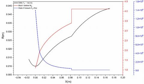
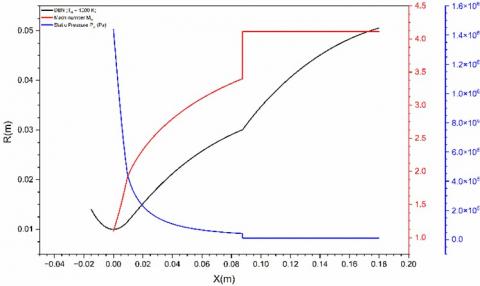
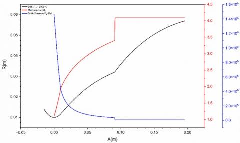
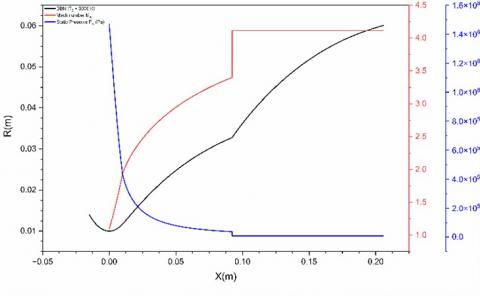
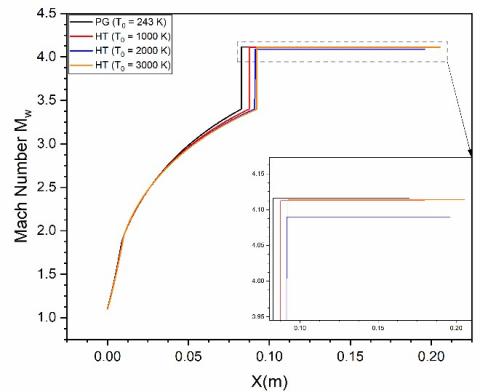
Figures 9-12 illustrate the evolution of wall Mach number and static pressure for each nozzle configuration (perfect gas, 1000 K, 2000 K, and 3000 K). It is observed that both the Mach number and static pressure follow similar trends across all four configurations, despite variations in stagnation temperature.
The Mach number increases, while the static pressure decreases rapidly at the throat—corresponding to the transonic region—and in the initial expansion zone. In the divergent section of the first bell, these variations become more gradual, with the Mach number reaching its maximum value and the static pressure reaching its minimum at the exit of the base nozzle. At the junction point J, both the Mach number and static pressure exhibit a discontinuity, assuming two distinct values due to the presence of a centered Prandtl–Meyer expansion wave. This expansion wave induces an abrupt increase in Mach number and a corresponding sharp drop in static pressure. Along the entire second bell (extension), both the Mach number and static pressure remain constant, as expected from the constant-pressure design approach.
Figure 9. Wall Mach number and static pressure variations: T0 = 243 K
Figure 10. Wall Mach number and static pressure variations: T0 = 1000 K
Figure 11. Wall Mach number and static pressure variations: T0 = 2000 K
Table 4 presents the wall thermodynamic parameters attained at key sections of the four dual-bell nozzle configurations: specifically, at the exit of the first bell (i.e., the junction point) and at the exit of the second bell. These parameters include the local Mach number, static pressure, static temperature, and density. This data enables a detailed comparative analysis of the flow behavior and thermodynamic state along the nozzle wall under varying stagnation temperatures.
Table 4. Dual-bell nozzle thermodynamic parameters comparison
|
DBN |
Mach Number at Exit of the 1st Bell |
Mach Number at Exit of the 2nd Bell |
Static Pressure at Exit of the 1st Bell (Pa) |
Static Pressure at Exit of the 2nd Bell (Pa) |
|
GP |
3.399530 |
4,1159 |
45404.430000 |
13450,7 |
|
1000 |
3.399377 |
4,1128 |
41108.670000 |
10541 |
|
2000 |
3.399938 |
4,09 |
38250.370000 |
9501,8 |
|
3000 |
3.399701 |
4,1141 |
37255.050000 |
8701,62 |
|
DBN |
Static Temperature (K) at Exit of the 1st Bell |
Static Temperature (K) at Exit of the 2nd Bell |
Density (kg/m3) at Exit of the 1st Bell (Pa) |
Density (kg/m3) at Exit of the 2nd Bell |
|
GP |
73.38372 |
55.3533 |
2.15171 |
0.85368 |
|
1000 |
340.1063 |
258.81 |
0.421 |
0.14413 |
|
2000 |
734.6148 |
573.381 |
0.18136 |
0.0565 |
|
3000 |
1132.894 |
880.52 |
0.11454 |
0.03466 |
Figure 12. Wall Mach number and static pressure variations: T0 = 3000 K
3.4 Performance comparison of the four dual-bell nozzle designs based on method of characteristics (MoC) calculations
Table 5 presents the performance metrics of each nozzle configuration (N1 to N4) in terms of the generated thrust force F and the thrust coefficient Cf. It is observed that the dual-bell nozzle configuration with T0 = 3000 K (N4) exhibits the highest performance, delivering the greatest thrust force and thrust coefficient. In contrast, the perfect gas configuration ith T0 = 243 K (N1) shows the lowest values for both performance indicators. This trend is primarily attributed to the difference in exit area ratio: the nozzle operating at T0 = 3000 K features a significantly larger exit area, allowing for more efficient expansion and greater momentum transfer, whereas the configuration with T0 = 243 K has a smaller exit area ratio, limiting its expansion capability and resulting performance.
Table 5. Performances comparison
|
DBN |
Thrust Force (N) |
Thrust Coefficient CF |
|
GP |
1697.78895 |
1.801409826161441 |
|
1000 |
1768.55141 |
1.8764911198448261 |
|
2000 |
1873.22419 |
1.987552376559705 |
|
3000 |
1986.84825 |
2.1081112352873208 |
3.5 MoC thermodynamic parameters comparison
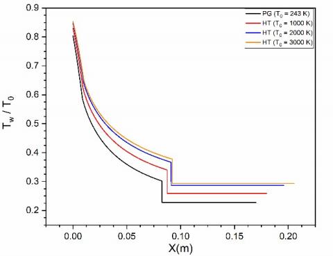
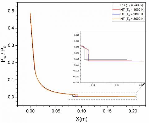
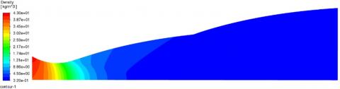
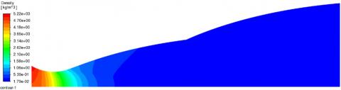
Figure 13 illustrates the comparison of wall Mach number contours for the four dual-bell nozzle (DBN) configurations. Figure 14 presents the corresponding comparison of normalized wall static temperature contours, while Figure 15 shows the normalized wall static pressure contours.
Figure 13. DBN wall Mach number contours comparison
Figure 14. Wall static temperature contours comparison
3.6 CFD calculations
We performed computational fluid dynamics (CFD) calculations after obtaining the dual-bell nozzle (DBN) designs and evaluating the flow parameters using the method of characteristics (MoC). These CFD simulations are crucial for analyzing high-speed compressible flows in rocket nozzles, as they enable the precise prediction of performance metrics, detailed examination of internal and external flow behaviors, and design optimization under various operational conditions. Additionally, the CFD results provide a valuable basis for comparison with the MoC-based predictions, thereby reinforcing the accuracy and robustness of the proposed nozzle configurations.
Figure 15. DBN normalized wall static pressure contours comparison
3.6.1 Mesh sensitivity study
Two-dimensional, axisymmetric, steady-state Reynolds-Averaged Navier–Stokes (RANS) simulations were performed using the finite volume commercial solver ANSYS Fluent 2019R1. The working fluid was treated as an ideal gas, and Sutherland’s law was employed to account for the temperature dependence of dynamic viscosity.
The numerical method implemented in Fluent is based on the finite volume approach, wherein the integral forms of the governing equations for continuity, momentum, energy, and turbulence are discretized and solved using a density-based solver. The continuity, momentum, and energy equations were coupled and solved simultaneously. These equations were linearized in an implicit manner, and the resulting system of equations was solved for all control volumes concurrently. To close the RANS equations, the Shear Stress Transport (SST) k–ω turbulence model was adopted, owing to its robustness and accuracy in capturing flow features involving adverse pressure gradients and boundary layer separation.
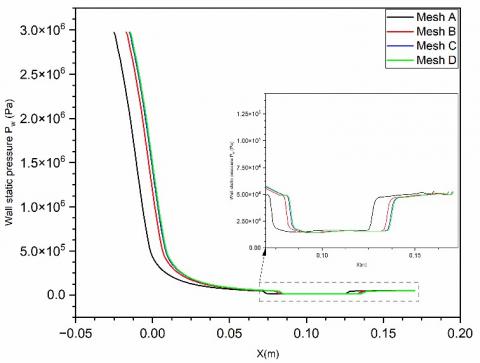
A structured mesh comprising 120,360 quadrilateral cells was employed in the present study. The computational grid was generated using the commercial pre-processing software ANSYS Meshing. The final mesh configuration, referred to as Grid C, was selected based on a comprehensive mesh sensitivity analysis, see Figure 16. Table 6 presents a summary of the various mesh densities considered, ranging from the coarse grid (Mesh A) to the very fine grid (Mesh D).
Figure 16. Mesh sensitivity analysis
3.6.2 Thermodynamics parameters contours
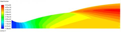
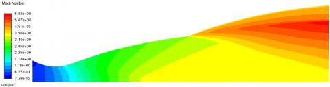
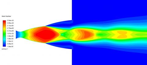
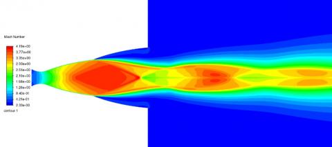
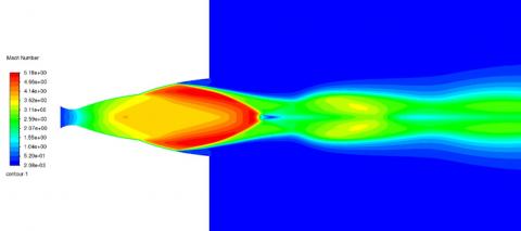
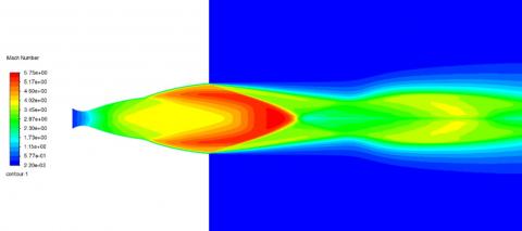
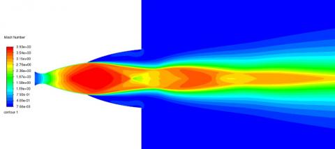
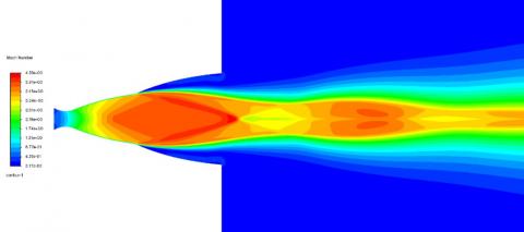
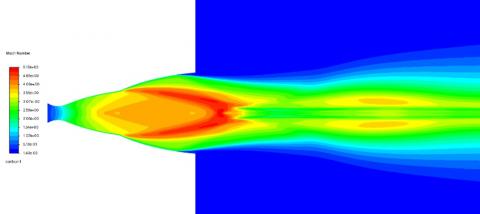
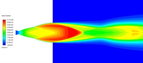
Figures 17-32 provide a detailed illustration of the evolution of the main thermodynamic parameters (Mach number, static pressure, static temperature, and density) across different dual-bell nozzle (DBN) configurations subjected to varying stagnation temperatures T0 (243, 1000, 2000, 3000) [K]. These distributions provide deeper insight into the behavior of compressible flows in high- temperature conditions.
Mach number. The analysis of the Mach number contours (Figures 17-20) highlights a progressive acceleration of the flow within the nozzle, with supersonic values exceeding Mach 4 at the wall nozzle exit. The transition between the two bells (junction J) is characterized by a centered Prandtl-Meyer expansion wave, resulting in abrupt evolution of thermodynamic parameters. The influence of stagnation temperature is particularly evident: at T0 = 3000 K, the flow expands more significantly, leading to a slightly higher final Mach number. This confirms that high-enthalpy gases require a longer expansion to fully convert thermal energy into kinetic energy.
Table 6. Sensitivity mesh analysis
|
Grid |
Mesh A (Coarse) |
Mesh B (Medium) |
Mesh C (Refined) |
Mesh D (Very fine) |
|
Number of elements |
17500 |
70000 |
120360 |
140420 |
|
Number of nodes |
17801 |
70601 |
120100 |
140890 |
Figure 17. Mach number contour: T0 = 243 K (Perfect gas model)
Figure 18. Mach number contour: T0 = 1000 K (High-Temperature gas model)
Figure 19. Mach number contour: T0 = 2000 K (Perfect gas model)
Figure 20. Mach number contour: T0 = 3000 K (High-Temperature gas model)
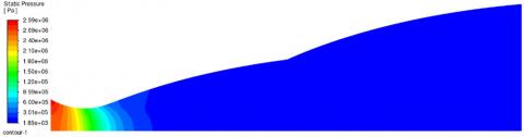
Figure 21. Static pressure contour: T0 = 243 K (Perfect gas model)
Figure 22. Static pressure contour: T0 = 1000 K (High-Temperature gas model)
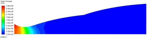
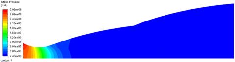
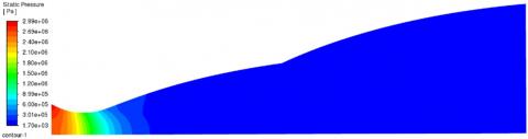
Static pressure, temperature and density. Figures 21-24 present the static pressure contours, where a sharp pressure drop is observed at the throat, corresponding to the subsonic-to-supersonic transition. In the second bell, the pressure stabilizes, in accordance with the “constant-pressure” design principle of dual-bell nozzles. An increase in T0 enhances expansion, resulting in a significantly lower exit pressure. This behavior aligns with the expected dynamics of high-temperature gases, which undergo more intense expansion and thus require an adapted geometry to maintain efficient energy transfer.
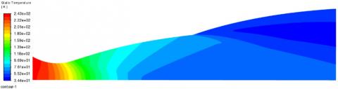
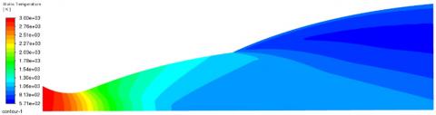
Regarding the static temperature contours (Figures 25-28), a global decrease along the nozzle is observed, reflecting the progressive conversion of thermal energy into kinetic energy. However, at high stagnation temperatures, the residual exit temperature remains elevated, indicating that even after substantial expansion, the gases retain a significant portion of their enthalpy. This aspect has critical implications for nozzle material selection, particularly in regions exposed to intense thermal loads.
Finally, the density contours (Figures 29-32) reveal a sharp drop downstream of the throat, typical of supersonic expansion. At elevated temperatures, the gas density at the nozzle exit is considerably lower, which reduces mass thrust. However, this rarefaction is compensated by a higher exhaust velocity, resulting in improved specific impulse.
Figure 23. Static pressure contour: T0 = 2000 K (Perfect gas model)
Figure 24. Static pressure contour: T0 = 3000 K (High-Temperature gas model)
Figure 25. Static temperature contour: T0 = 243 K (Perfect gas model)
Figure 26. Static temperature contour: T0 = 1000 K (High-Temperature gas model)
Figure 27. Static temperature contour: T0 = 2000 K (Perfect gas model)
Figure 28. Static temperature contour: T0 = 3000 K (High-Temperature gas model)
Figure 29. Density contour: T0 = 243 K (Perfect gas model)
Figure 30. Density contour: T0 = 1000 K (High-Temperature gas model)
Figure 31. Density contour: T0 = 2000 K (Perfect gas model)
Figure 32. Density contour: T0 = 3000 K (High-Temperature gas model)
In summary, increasing the stagnation temperature leads to a higher Mach number, lower exit pressure and density, and a higher residual temperature. These results confirm that optimizing performance in high-temperature regimes requires nozzles with tailored geometries, including extended lengths and enlarged exit sections, in accordance with theoretical predictions based on the perfect gas laws with variable specific heat capacity.
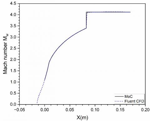
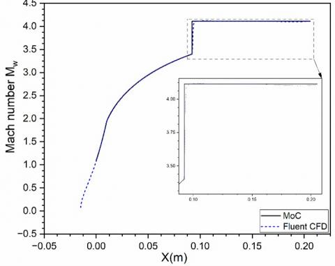
Figure 33. DBN wall Mach number comparison MoC vs CFD, (T0 = 243 K)
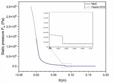
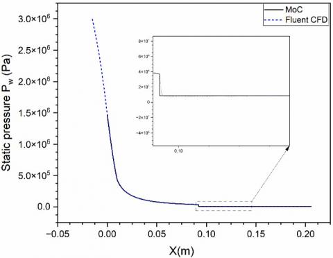
Figure 34. DBN wall static pressure comparison MoC vs CFD, (T0 = 243 K)
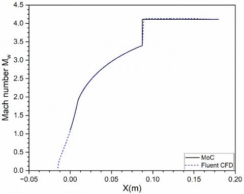
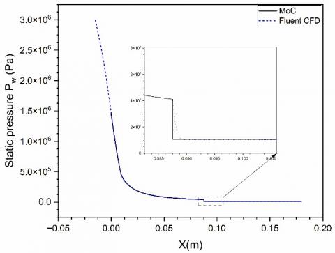
Comparison curves between MoC and CFD for each nozzle. Figures 33-38, along with Tables 7 and 8, compare the results obtained using the method of characteristics (MoC) and computational fluid dynamics (CFD) simulations for dual-bell nozzle configurations subjected to different stagnation temperatures T0 (243, 1000, 2000, 3000) [K].
A) DBN (T0 = 243 K):
Figures 33 and 34 present the variation of the Mach number and static pressure along the wall of the dual-bell nozzle, comparing the results from the MoC and CFD for a stagnation temperature of T0 = 243 K.
A very good agreement is observed between the two approaches, with a relative error of less than 0.5% along the entire nozzle length. The Mach number distribution shows a continuous acceleration of the flow up to the exit, achieving a stable supersonic regime. This figure highlights the ability of the MoC to accurately predict flow acceleration under perfect gas conditions.
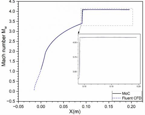
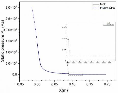
B) DBN (T0 = 1000 K):
Figures 35 and 36 illustrate the Mach number and static pressure distribution for a higher stagnation temperature (T0 = 1000 K). As in the previous configuration, the flow accelerates progressively, reaching slightly higher values at the exit. The agreement between MoC and CFD remains very satisfactory, with discrepancies below 0.5%, despite the introduction of a more complex thermodynamic model with variable specific heat Cp (T). This result demonstrates the robustness of the MoC even in the presence of non-negligible thermal variations.
Figure 35. DBN wall Mach number comparison MoC vs CFD, (T0 = 1000 K)
Figure 36. DBN wall static pressure comparison MoC vs CFD, (T0 = 1000 K)
C) DBN (T0 = 2000 K):
Figures 37 and 38 show the comparison of Mach and static pressure profiles for an even higher stagnation temperature (T0 = 2000 K). The Mach number evolution follows the same trend as the previous cases, with a slight increase in the maximum exit value. The deviation between the two methods remains limited, confirming that the variable Cp(T) model implemented in the MoC accurately captures the flow dynamics even under more thermally aggressive conditions.
Table 7. MoC versus CFD comparison for wall Mach number
|
DBN |
Mach Number at Exit of the 1st Bell (MoC) |
Mach Number at Exit of the 1st Bell (CFD) |
Relative Error (%) |
|
GP |
3.399530 |
3.389655 |
0.29048 |
|
1000 |
3.399377 |
3.385113 |
0.4196 |
|
2000 |
3.399938 |
3.390074 |
0.29012 |
|
3000 |
3.399701 |
3.389629 |
0.2963 |
|
DBN |
Mach Number at Exit of the 2nd Bell (MoC) |
Mach Number at Exit of the 2nd Bell (CFD) |
Relative Error (%) |
|
GP |
4,1159 |
4.09792 |
0.4368 |
|
1000 |
4,1128 |
4.10338 |
0.229 |
|
2000 |
4,09 |
4.07894 |
0.27 |
|
3000 |
4,1141 |
4.10617 |
0.193 |
Figure 37. DBN wall Mach number comparison MoC vs CFD, (T0 = 2000 K)
Table 7 reports the Mach number values obtained by both MoC and CFD at the ends of the two bells of the nozzle for the four stagnation temperatures studied. Relative deviations are consistently below 0.5%, indicating excellent agreement between the two methods. The Mach number at the exit of the second bell slightly increases with temperature (from 4.0979 to 4.1141), reflecting the more pronounced expansion of hot gases. This table confirms that the MoC enables reliable estimation of flow velocity across a wide range of thermal conditions.
Figure 38. DBN wall static pressure comparison MoC vs CFD, (T0 = 2000 K)
Figure 39. DBN wall Mach number comparison MoC vs CFD, (T0 = 3000 K)
D) DBN (T0 = 3000 K):
Figures 39 and 40 represent the most extreme thermodynamic configuration analyzed, with a stagnation temperature of T0 = 3000 K, which places the flow under conditions of extremely high enthalpy. At these elevated temperatures, the fluid properties, especially the specific heat Cp, exhibit significant variation with temperature. Despite these complex, high-enthalpy conditions, the method of characteristics (MoC) has demonstrated its exceptional ability to accurately capture the flow behavior, with a remarkably low relative deviation from computational fluid dynamics (CFD) results, consistently staying below 0.3%. This result underscores the robustness of the MoC in predicting key flow parameters, even under extreme conditions that typically challenge traditional simulation methods. What is particularly notable in this scenario is the incorporation of a temperature-dependent specific heat capacity (Cp(T)) in the MoC formulation.
Figure 40. DBN wall static pressure comparison MoC vs CFD, (T0 = 3000 K)
Table 8. MoC versus CFD comparison for wall static pressure
|
DBN |
Static Pressure at Exit of the 1st Bell (Pa) (MoC) |
Static Pressure at Exit of the 1st Bell (Pa) (CFD) |
Relative Error (%) |
|
GP |
45404.430000 |
44986.922 |
0.9195 |
|
1000 |
41108.670000 |
40945.731 |
0.3964 |
|
2000 |
38250.370000 |
38011.477 |
0.6246 |
|
3000 |
37255.050000 |
37118.782 |
0.3658 |
|
DBN |
Static Pressure at Exit of the 2nd Bell (Pa) (MoC) |
Static Pressure at Exit of the 2nd Bell (Pa) (CFD) |
Relative Error (%) |
|
GP |
13450,7 |
13114.77 |
2.4975 |
|
1000 |
10541 |
10278.46 |
2.4907 |
|
2000 |
9501,8 |
9388.964 |
1.188 |
|
3000 |
8701,62 |
8497.55 |
2.3452 |
Table 8 summarizes the static pressure results calculated at the same locations as for the Mach number, for each stagnation temperature T0. Slightly larger discrepancies are observed compared to the Mach number, particularly in the second bell, with differences reaching up to 2.5%.
This greater sensitivity is attributed to the fact that pressure is directly affected by turbulence and viscous losses, which are not accounted for in the MoC. Nonetheless, the results remain within an acceptable error margin, confirming that the MoC retains practical relevance for pressure prediction in compressible supersonic flow regimes.
This section presents a comprehensive numerical analysis of the flow transition phenomena in dual-bell nozzles N1, N2, N3, and N4, each characterized by a different stagnation temperature: 243 K, 1000 K, 2000 K, and 3000 K, respectively, under varying nozzle pressure ratios (NPRs). These values are selected to cover a representative range of operating conditions that may be encountered in practical propulsion systems, from cold-flow experiments to high-temperature rocket engine flows. The analysis is performed over a broad range of NPRs to capture the transition from the sea-level operating mode, in which the flow remains attached to the primary contour, to the high-altitude mode, where the flow separates and attaches to the extension contour of the dual-bell nozzle.
The principal aim is to numerically determine the critical nozzle pressure ratio, denoted as NPRtransition at which this mode transition occurs for each nozzle configuration. By systematically varying the stagnation temperature, the study further investigates its influence on NPRtransition, thereby providing insight into thermodynamic effects on dual-bell nozzle performance. The results obtained in this investigation are expected to contribute to a better understanding of the sensitivity of flow transition to thermal conditions at the nozzle inlet. Such an understanding is crucial for the accurate prediction and control of altitude transition behavior in dual-bell nozzles, particularly in applications where high thermal loads and variable operating conditions are encountered, such as in advanced launch vehicle propulsion systems.
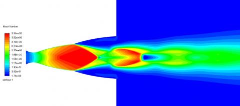
Figure 41. CFD Mach number contour (DBN PG model, T0 = 243 K), NPR = 23
Figure 42. CFD Mach number contour (DBN PG model, T0 = 243 K), NPR = 33
Figure 43. CFD Mach number contour (DBN PG model, T0 = 243 K), NPR = 54.5
Figure 44. CFD Mach number contour (DBN PG model, T0 = 243 K), NPR = 79
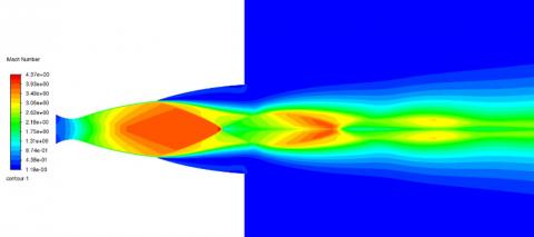
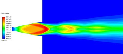
Figures 41-45 illustrate the computed Mach number contours obtained from CFD simulations of the N1 dual-bell nozzle (DBN) under a range of nozzle pressure ratios (NPRs). These simulations cover operating conditions from NPR=23, representative of the sea-level mode, to NPR=150, corresponding to the high-altitude mode where the exhaust jet remains significantly underexpanded. In the sea-level regime, the flow adheres closely to the contour of the base nozzle, while at higher NPRs, the flow expands into the extension nozzle, exhibiting shock structures and characteristic separation behavior typical of underexpanded supersonic flows. The numerical analysis allowed for the precise determination of the transition point between the two operating modes, which was found to occur at a critical pressure ratio of NPRtransition = 34.3. This value marks the onset of flow attachment within the extension, indicating the switch from sea-level to high-altitude operation.
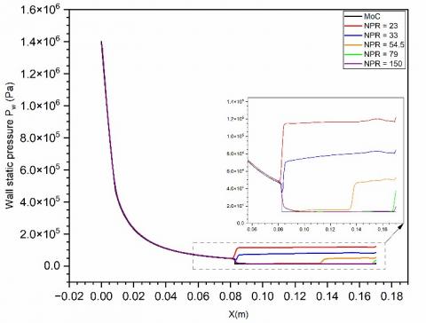
To complement the Mach number visualization, Figure 46 presents the corresponding wall pressure distributions for the range of NPRs considered. These distributions provide further insight into the evolution of flow separation, reattachment, and the overall pressure recovery along the nozzle wall as a function of increasing NPR.
Figure 45. CFD Mach number contour (DBN PG model, T0=243 K), NPR=150
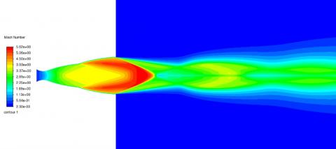
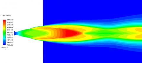
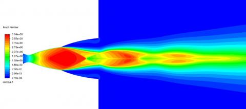
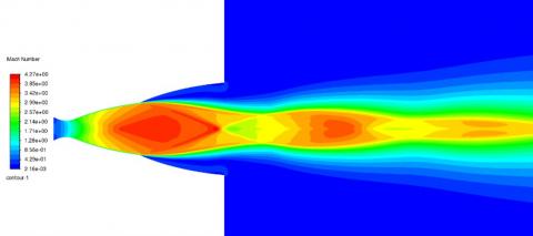
Figures 47-51 display the Mach number contours calculated through CFD simulations for the N2 dual-bell nozzle (DBN) across a range of nozzle pressure ratios (NPRs). The examined
range spans from NPR=30, indicative of sea-level operation, to NPR = 375, which characterizes the high-altitude regime where the exhaust flow remains markedly underexpanded. Under sea-level conditions, the jet remains attached to the contour of the base nozzle.
As the NPR increases, the flow extends into the nozzle's second bell, accompanied by the formation of shock waves and flow separation phenomena that are characteristic of supersonic underexpanded jets.
Numerical results enabled the accurate identification of the transition between these operating regimes, occurring at a critical NPR of NPRtransition = 56.74, signifying the point at which the flow reattaches to the wall within the extension, thus marking the shift to high-altitude mode.
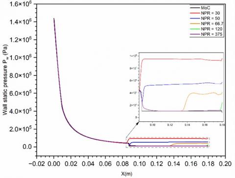
To further elucidate this behavior, Figure 52 shows the associated wall pressure distributions for the evaluated NPRs, highlighting the progression of flow separation, reattachment, and pressure recovery along the nozzle wall with increasing NPR.
Figure 46. Wall pressure distributions with varying NPR (DBN PG model, T0 = 243 K)
Figure 47. CFD Mach number contour (DBN HT model, T0 = 1000 K), NPR = 30
Figure 48. CFD Mach number contour (DBN HT model, T0 = 1000 K), NPR = 50
Figure 49. CFD Mach number contour (DBN HT model, T0 = 1000 K), NPR = 66.7
Figure 50. CFD Mach number contour (DBN HT model, T0 = 1000 K), NPR = 120
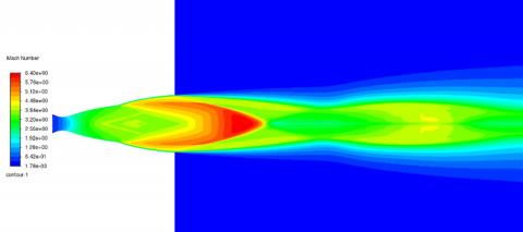
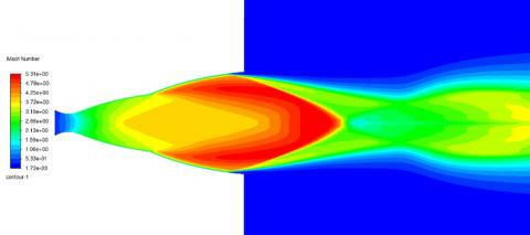
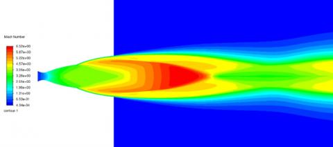
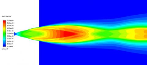
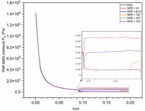
Figures 53-57 show the Mach number contours resulting from CFD simulations of the N3 dual-bell nozzle (DBN) across a range of nozzle pressure ratios (NPRs). The study encompasses conditions from NPR = 43, associated with sea-level operation, up to NPR = 450, indicative of high-altitude functioning where the jet is highly underexpanded. The transition between these regimes was numerically determined to occur at a critical value of NPRtransition = 70.4, marking the onset of flow attachment in the extension and the shift to high-altitude mode. Figure 58 complements this analysis by presenting wall pressure distributions for the same NPR range, offering insight into the progression of separation, reattachment, and pressure recovery along the nozzle wall.
Figure 51. CFD Mach number contour (DBN HT model, T0 = 1000 K), NPR = 375
Figure 52. Wall pressure distributions with varying NPR (DBN HT model, T0 = 1000 K)
Figure 53. CFD Mach number contour (DBN HT model, T0 = 2000 K), NPR = 43
Figure 54. CFD Mach number contour (DBN HT model, T0 = 2000 K), NPR = 62.5
Figure 55. CFD Mach number contour (DBN HT model, T0 = 2000 K), NPR = 107
Figure 56. CFD Mach number contour (DBN HT model, T0 = 2000 K), NPR = 287
Figure 57. CFD Mach number contour (DBN HT model, T0 = 2000 K), NPR = 450
Figure 58. Wall pressure distributions with varying NPR (DBN HT model, T0 = 2000 K)
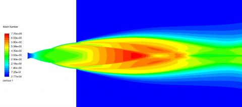
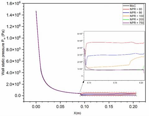
Figures 59-63 depict the Mach number contours obtained from CFD simulations of the N4 dual-bell nozzle (DBN) over a wide range of nozzle pressure ratios (NPRs), spanning from NPR = 60—representative of sea-level conditions—to NPR = 750, characteristic of high-altitude operation with a strongly underexpanded jet. The transition between these two operating modes was identified numerically at a critical NPR of 89.63. Figure 64 presents the corresponding wall pressure profiles across the same NPR interval.
The numerical investigation conducted on the dual-bell nozzle (DBN) under varying thermodynamic conditions has revealed a clear dependence of the transitional nozzle pressure ratio (NPRtransition) on the stagnation temperature of the flow.
For the perfect gas (PG) model at 243 K, the transition from sea-level mode to high-altitude mode occurs at NPRtransition = 34.3. In contrast, for high-temperature (HT) real-gas models, the transition point increases with temperature: 56.74 at 1000 K, 70.4 at 2000 K, and 89.63 at 3000 K.
Figure 59. CFD Mach number contour (DBN HT model, T0 = 3000 K), NPR = 60
Figure 60. CFD Mach number contour (DBN HT model, T0 = 3000 K), NPR = 86
Figure 61. CFD Mach number contour (DBN HT model, T0 = 3000 K), NPR = 100
Figure 62. CFD Mach number contour (DBN HT model, T0 = 3000 K), NPR = 200
Figure 63. CFD Mach number contour (DBN HT model, T0 = 3000 K), NPR = 750
Figure 64. Wall pressure distributions with varying NPR (DBN HT model, T0 = 3000 K)
This trend clearly demonstrates that higher stagnation temperatures delay the onset of flow attachment in the nozzle extension, requiring higher NPRs to initiate the transition to high-altitude mode.
The observed ordering—NPRtransition(243 K) < NPRtransition(1000 K) < NPRtransition(2000 K) < NPRtransition(3000 K) highlights the significant influence of thermodynamic effects on nozzle flow behavior. These findings underscore the necessity of accounting for real-gas effects in high-enthalpy nozzle flow simulations, particularly in the design and performance prediction of DBNs operating across a wide range of altitudes and thermal conditions.
This study examined the complex behavior of supersonic flows in nozzles operating under high-temperature conditions, where the classical perfect gas (PG) model becomes increasingly inadequate. Recognizing that the PG assumption is valid only at relatively low temperatures, the thermodynamic model was extended to account for real-gas effects, specifically tailored for air at elevated temperatures—well above 1000 K but below the chemical dissociation threshold. These conditions are representative of those encountered in practical aerospace propulsion systems.
The analysis revealed a strong sensitivity of nozzle geometry and thermodynamic performance indicators to stagnation temperature, even when the exit Mach number is held constant. In particular, the design and evaluation of dual-bell nozzles at temperatures up to 3000 K demonstrated that traditional PG-based approaches significantly underestimate the geometric requirements. For instance, the total length and exit area increased markedly—from 17 cm and 0.0059 m² at 243 K to 20.5 cm and 0.0113 m² at 3000 K, respectively.
Through the method of characteristics (MOC) and validated CFD simulations employing the k–ω SST turbulence model (with discrepancies below 3%), it was shown that elevated thermal loads intensify the expansion process, thereby enhancing energy conversion. This is reflected in slightly increased exit Mach numbers (4.116 vs. 4.114) and significantly reduced static pressures (8701 Pa vs. 13,450 Pa at 3000 K). Moreover, the nozzle pressure ratio (NPR) required to trigger the flow regime transition rose from 34.3 to 89.63, illustrating the impact of thermal effects on flow separation dynamics. The thrust coefficient also increased by approximately 17% (from 1.801 to 2.108), confirming the potential gains in propulsion performance.
However, these performance improvements are accompanied by substantial engineering challenges. The severe thermal gradient (ΔT ≈ 2119 K over a 20 cm nozzle length) induces significant thermo-mechanical stresses that can limit operational lifetime if not properly addressed. This highlights the necessity for advanced high-temperature materials—such as carbon–carbon composites, refractory metal alloys (e.g., niobium-based), and ceramic matrix composites—capable of sustaining extreme temperatures and cyclic thermal loading. Complementary thermal protection measures, including regenerative or transpiration cooling and ablative liners, are also essential to ensure both flow management and structural durability under these extreme conditions.
While the present results are based on air as the working fluid, the modeling framework is generalizable to other gases of aerospace interest, including helium and hydrogen. Given their markedly different specific heat capacities, molecular weights, and thermal conductivities, future investigations will quantify how these properties influence nozzle geometry, expansion efficiency, and flow separation characteristics at high temperatures. Such analyses will support the broader applicability of the proposed methodology to diverse propulsion concepts.
In summary, this work establishes a novel high-temperature design framework for dual-bell nozzles, integrating analytical modeling with CFD validation to deliver thermodynamically optimized and structurally resilient designs. Future research will involve (i) extending the real-gas formulation to other propellants, (ii) conducting coupled thermal–mechanical simulations to assess material behavior under operational loads, and (iii) performing experimental or high-fidelity numerical studies of active flow-control strategies, such as fluidic injection and localized heating, to enhance transition control. These efforts aim to bridge the gap between high-fidelity design methodologies and practical, flight-ready propulsion hardware.
|
CFD |
computational fluid dynamics |
|
DBN |
dual-bell nozzle |
|
PG |
perfect gas model |
|
HT |
high-temperature gas model |
|
MoC |
method of characteristics |
|
NPR |
nozzle pressure ratio (P0/Pa) |
|
TIC |
truncated ideal contour |
|
CP |
constant pressure |
|
NPRtransition |
transitional nozzle pressure ratio |
|
Symbols |
|
|
A |
cross section area |
|
a |
sound velocity |
|
CF |
thrust force coefficient |
|
C+ |
right running characteristic |
|
C- |
left running characteristic |
|
α0, α1, α2, …, αn |
interpolation polynomial coefficients |
|
Cp(T) |
specific heat at constant pressure for HT gas model |
|
γ(T) |
specific heat ratio for HT gas model |
|
H |
enthalpy |
|
T0 |
stagnation temperature |
|
P0 |
stagnation pressure |
|
L |
length of nozzle |
|
M |
Mach number |
|
ν |
Prandtl–Meyer function |
|
μ |
Mach angle |
|
ρ |
density |
|
N1 |
nozzle contour T0=243 K |
|
N2 |
nozzle contour T0=1000 K |
|
N3 |
nozzle contour T0=2000 K |
|
N4 |
nozzle contour T0=3000 K |
[1] Foster, C., Cowles, F. (1949). Experimental study of gas-flow separation in over-expanded exhaust nozzles for rocket motors. Progress Report No. 4-103. Pasadena, CA: Jet Propulsion Laboratory.
[2] Horn, M., Fisher, S. (1994). Altitude compensating nozzles. Rocketdyne Division, NASA-CR-194719.
[3] Frey, M., Hagemann, G. (1999). Critical assessment of dual bell nozzles. Journal of Propulsion and Power, 15(1): 137-143. https://doi.org/10.2514/2.5402
[4] Immich, H., Caporicci, M. (1996). FESTIP technology developments in liquid rocket propulsion for reusable launch vehicles. Paper Presented at the 32nd AIAA Joint Propulsion Conference, Lake Buena Vista, FL. https://doi.org/10.2514/6.1996-3113
[5] Miyazawa, M., Takeuchi, S., Takahashi, M. (2002). Flight performance of dual bell nozzles. Paper Presented at the 40th Aerospace Sciences Meeting & Exhibit, Reno, NV. https://doi.org/10.2514/6.2002-686
[6] Hagemann, G., Terhardt, M., Haeseler, D., Frey, M. (2002). Experimental and analytical design verification of the dual bell concept. Journal of Propulsion and Power, 18(1). https://doi.org/10.2514/2.5905
[7] Tcherak, A., Kbab, H., Haddad, A. (2025). Proposal of a novel dual-bell axisymmetric rocket propulsive nozzle design. In 2025 9th International Conference on Mechanical Engineering and Robotics Research (ICMERR), Barcelona, Spain, pp. 198-202. https://doi.org/10.1109/ICMERR64601.2025.10949881
[8] Nürnberger-Genin, C., Stark, R. (2009). Flow Transition in dual bell nozzles. Shock Waves, 19: 265-270. https://doi.org/10.1007/s00193-008-0176-4
[9] Loosen, S., Meinke, M. Schröder, W. (2020). Numerical Investigation of jet-wake interaction for a dual-bell nozzle. Flow Turbulence Combust, 104: 553-578. https://doi.org/10.1007/s10494-019-00056-6
[10] Scharnowski, S., Kähler, C.J. (2021). Investigation of the base flow of a generic space launcher with dual-bell nozzle. CEAS Space Journal, 13: 197-216. https://doi.org/10.1007/s12567-020-00333-5
[11] Scarlatella, G., Sieder-Katzmann, J., Propst, M., Heutling, T., et al. (2025). RANS simulations of advanced nozzle performance and retro-flow interactions for vertical landing of reusable launch vehicles. Aerospace, 12(2): 124. https://doi.org/10.3390/aerospace12020124
[12] Toufik, H., Sellam, M., Kbab, H., Bergheul, S. (2019). Design and wall fluid parameters evaluation of the dual bell nozzle. International Journal of Engineering Research and Technology, 12(7): 1064-1074.
[13] Kbab, H., Abada, O., Haif, S. (2023). Numerical investigation of supersonic flows on innovative nozzles (Dual bell nozzle). Journal of Applied Fluid Mechanics, 16(4): 819-829. https://doi.org/10.47176/jafm.16.04.1551
[14] Kbab, H., Sellam, M., Hamitouche, T., Bergheul, S., Lagab, L. (2017). Design and performance evaluation of a dual bell nozzle. Acta Astronautica, 130: 52-59. https://doi.org/10.1016/j.actaastro.2016.10.015
[15] Liu, Y.Z., Li, P. (2023). Analysis of the aspiration drag in dual-bell nozzles. International Journal of Aeronautical and Space Sciences, 24: 467-474. https://doi.org/10.1007/s42405-022-00541-9
[16] Wu, K.X., Sohn, G.C., Deng, R.Y., Jia, H., Kim, H.D., Su, X.H. (2023). Study on wall pressure and hysteresis behaviors of a novel dual bell nozzle. Journal of Mechanical Science and Technology, 37(9): 4639-4646. https://doi.org/10.1007/s12206-023-0819-5
[17] Ferrero, A., Conte, A., Martelli, E., Nasuti, F., Pastrone, D. (2022). Dual bell nozzle with fluidic control of transition for space launchers. Acta Astronautica, 193: 130-137. https://doi.org/10.1016/j.actaastro.2021.12.048
[18] Patil, P.J., Mankar, K., Mishra, A.K. (2024). Computational study on flow characteristics of dual bell nozzle with varying altitude effect. In: Choubey, G., Tripathi, S., Singh, V.K., Subbarao, P.M.V. (eds) Advances in Thermal Engineering. ICFAMMT 2024. Lecture Notes in Mechanical Engineering. Springer, Singapore. https://doi.org/10.1007/978-981-97-4500-5_20
[19] Léger, L., Zmijanovic, V., Sellam, M., Chpoun, A. (2021). Experimental investigation of forced flow regime transition in a dual bell nozzle by secondary fluidic injection. International Journal of Heat and Fluid Flow, 89: 108818. https://doi.org/10.1016/j.ijheatfluidflow.2021.108818
[20] Legros, B., Léger, L., Kourta, A., Chpoun, A., Sellam, M. (2023). Parametrical investigation of transverse injection in a dual bell nozzle during altitude varying conditions. Journal of Propulsion and Power, 39(6): 875-885. https://doi.org/10.2514/1.B39077
[21] Legros, B., Léger, L., Kourta, A., Sefir, A., Sellam, M., Chpoun, A. (2022). Fluidic control of flow regime transition and retransition in a dual-bell launcher nozzle. In 8th Edition of the 3AF Space Propulsion Conference, 3AF, Estoril, Portugal, pp. 1-10.
[22] Legros, B., Léger, L., Chpoun, A., Sellam, M., Kourta, A. (2023). Potential benefits of radial secondary injection of helium in dual-bell nozzles. In 57th 3AF International Conference on Applied Aerodynamics, 3AF, Bordeaux, France, pp. 1-10.
[23] Legros, B., Léger, L., Kourta, A., Chpoun, A., Sellam, M., Gilard, V. (2025). Experimental and numerical investigation of transverse secondary injection in dual-bell nozzles for enhanced operating mode switch control. Acta Astronautica, 236: 667-683. https://doi.org/10.1016/j.actaastro.2025.06.063
[24] Raju, M., Suryan, A., Šimurda, D. (2021). Computational investigation of cooling effectiveness for film cooled dual-bell exhaust nozzle for LO2/LH2 liquid rocket engines. Energy Sources, Part A: Recovery, Utilization, and Environmental Effects, 47(1): 10315-10331. https://doi.org/10.1080/15567036.2021.1963885
[25] Chehat, T., Kbab, H., Hamaidia, W., Benaouda Zouaoui, B. (2025). Analysis of dual bell nozzle configurations: Design parameters and performance measurements. Journal of Applied Fluid Mechanics, 18(7): 1767-1781. https://doi.org/10.47176/jafm.18.7.3239