Kodjo Kpode*![]() | Yawovi Nougblega
| Yawovi Nougblega![]() | N'Détigma Kata
| N'Détigma Kata![]() | Hodo-Abalo Samah
| Hodo-Abalo Samah![]()
© 2025 The authors. This article is published by IIETA and is licensed under the CC BY 4.0 license (http://creativecommons.org/licenses/by/4.0/).
OPEN ACCESS
This study presents the numerical results of mixed convection in a habitat equipped with a photovoltaic chimney. The photovoltaic panel of the chimney captures solar radiation through a glazed upper surface and generates the electricity required to power a fan that accelerates the hot air flow at the chimney outlet. The main objective is to prevent reverse flow and eliminate air recirculation within the living space by combining the effects of thermal buoyancy and the kinetic impulse provided by the fan. These reverse flows and recirculations hinder the continuous and efficient renewal of the air. Using the simplified Navier-Stokes equations, solved by the finite volume method and a power law scheme, a calculation code was developed in Fortran. For Reynolds numbers below 45 and Rayleigh numbers ranging from 103 to 5 × 10⁵, simulations reveal the presence of recirculating flows. Beyond this threshold, the recirculations disappear, and the cavity is fully traversed by open streamlines. This phenomenon improves thermal comfort, leading to a significant decrease in temperatures within the living space and at the panel level.
photovoltaic chimney, solar chimney, reverse flow, air recirculation, energy efficiency
Buildings account for approximately 40% of global electricity consumption, with nearly 60% of this energy dedicated to heating and cooling purposes [1, 2]. Consequently, they contribute significantly to global carbon emissions, as highlighted in various studies [3-5]. Enhancing the energy efficiency of buildings is therefore considered one of the most effective strategies for reducing their carbon footprint [6, 7]. This includes insulation [8-10], green roofing or vegetation-based solutions [11], and natural ventilation strategies [12], among other elements that should be integrated from the design phase. To ensure continuous indoor air renewal in buildings located in areas with high solar radiation, passive systems such as solar chimneys can be employed [13, 14]. These systems have a significant impact on building energy consumption and contribute to reducing the energy required for cooling [15, 16]. This reduction can reach up to approximately 50% of the energy demand compared to mechanical ventilation systems [15].
The natural operation of a solar chimney is based on the principle of thermally induced convection (thermosiphon) [17]. Its effectiveness in contributing to thermal comfort within a building is generally evaluated based on the airflow rate or the velocity of the extracted air, both of which depend on geometric and thermal parameters [13].
Thus, to enhance the natural thermal draft, recent research has focused on optimizing heat transfer to the air flowing within the channel to increase buoyancy forces. These modern or optimized solar chimneys [18, 19] generally consist of two main walls: a glazing (collector) and an absorber or a photovoltaic (PV) panel [20-23]. Solar radiation passing through the glazing is absorbed by the absorber, which transfers heat to the air within the channel. Under these conditions, several studies [24, 25] have shown that a solar chimney can induce an air renewal rate varying between 8% and 45%, with a mass flow rate reaching up to 44.5 kg/s in summer when solar radiation is at its peak. However, this rate drops to values between 1.16% and 24.89% in winter due to reduced sunlight. The work of Abdeen et al. [18] also showed that the average air velocity in the solar chimney varies between 0.28 m/s and 0.52 m/s for average irradiance levels of 500 to 850 W/m² received by the absorber, respectively. Furthermore, it was observed that the airflow rate increases with the Rayleigh number (Ra), which is proportional to the thermal flux density. Finally, the work of Ren et al. [26] highlighted a correlation between the chimney inclination angle and the critical Rayleigh number. They demonstrated that reverse flow occurs at a relatively low Rayleigh number as the inclination angle increases.
Among the geometric parameters affecting the performance of a solar chimney are the inclination angle relative to the roof, as well as its dimensions such as thickness and width. Ren et al. [26] showed that the chimney maintains high efficiency, with airflow rate increasing as the Rayleigh number increases, when its inclination angle is less than 30°. The location of the openings also plays a crucial role in the airflow rate for the renewal of thermally polluted air. By analyzing three different configurations [27] - vertical outlet, horizontal outlet, and mid-level outlet - the authors observed that the chimney with a vertical outlet and openings oriented in the same direction generates a greater thermal draft. This naturally results in a higher volumetric flow rate compared to the other configurations.
The performance of a solar chimney is also measured by the velocity of the renewed air within the living space. This velocity depends on several geometric parameters, notably the chimney width, the thickness of the air gap, and the inclination angle [18, 28]. It has been observed that chimneys with excessively wide outlet openings are prone to reverse flows [29]. Regarding the height (or length) of the chimney, it does not appear to have a significant influence on the airflow rate. However, experimental studies by Jing et al. [30] have shown that an optimal ratio between spacing and height (spacing/height) is approximately 0.5, which maximizes the airflow rate through the chimney.
In the absence of reverse flows, Nguyen et al. [29] demonstrated that the thermal efficiency of a solar chimney can reach up to 90%. However, reverse flow and recirculation phenomena still occur. Although these are intrinsic to natural convective flows, the literature indicates that they depend on both the direction of heat flux and geometrical parameters. In the case of habitats of hot climates, the heat flux is generally directed downward due to significant thermal gains [31-33] through the roof exposed to solar radiation. Under these conditions, the flow structure within the living space becomes particularly complex, with the emergence of zones where buoyancy forces act favorably, but also regions characterized by reverse flows or recirculation [34, 35], potentially caused by the presence of obstacles (such as walls) or by gravitational effects. In addition to enhancing the buoyancy forces by the supply of heat, it is possible to strengthen the draft by introducing a forced impulse, which would help eliminate dead zones and recirculating flows detrimental to thermal comfort [36]. In other words, this involves providing additional kinetic energy to the fluid particles, complementing that generated by the conversion of thermal flux. Furthermore, through a comparative study of the performance between a fan powered by direct current from a photovoltaic (PV) panel and a solar chimney with an absorber plate of the same area as the PV panel, Klimeš et al. [37] made important observations. They found that, under identical solar incidence, the mass flow rate of air generated by the fan is three times higher than that of the solar chimney. It therefore seems possible to utilize the combined action of thermal thrust forces and the kinetic impulse from the fan powered by the PV to optimize thermal comfort.
In this context, a typical case of a building equipped with a photovoltaic chimney, referred to as an “active chimney”, is studied. In this chimney, the absorber plate is replaced by a photovoltaic panel, which powers the fan it is equipped with.
Although passive solar chimneys have been the subject of numerous studies, research on active configurations integrating a photovoltaic panel powering a fan remains limited. This hybrid system, combining the effects of thermal buoyancy and mechanical impulse, represents an innovative solution to improve air renewal and prevent reverse flows as well as recirculation zones. Thus, considering the unfavorable case where the flow remains laminar, this study aims to identify the relevant parameters for quantifying these transfers under the specific operating conditions of an active chimney.
The increase in the air exit velocity should allow the visualization of fully open streamlines, indicative of a complete air renewal within the cavity. This study will also provide useful numerical results for evaluating the efficiency of active chimneys integrated into buildings, with a focus on optimizing thermal comfort.
2.1 Physical domain and equations
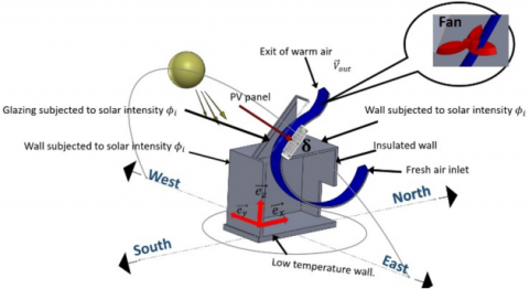
We consider a cavity with a rectangular cross-section equipped with a photovoltaic (PV) chimney, as illustrated in Figure 1. The photovoltaic panel (PV) of the chimney is exposed to solar radiation $\Phi_i$ through glazing. The chimney thus forms an airflow channel inclined at an angle $\delta=9^{\circ}$, with a thickness e. The inclination angle δ is selected to optimize the solar irradiation received by the photovoltaic (PV) panel, thereby ensuring sufficient electricity production to power the fan. This inclination falls within the recommended range for solar installations in the Sahel region, which benefits from high solar irradiance throughout the year [38].
Figure 1. Physical system
The air entering the chimney is heated by the photovoltaic panel, which is also assumed to generate the electrical energy required to operate the fan to which it is connected. The unfavorable laminar flow condition, characterized by weak buoyancy forces that limit optimal ventilation, is considered to evaluate the performance of the photovoltaic chimney in achieving complete renewal of the indoor air volume in a residential building. The flow is assumed to be incompressible and two-dimensional ($\left(\overrightarrow{\mathrm{e}}_{\mathrm{x}}, \overrightarrow{\mathrm{e}}_{\mathrm{z}}\right)$ plane), and the governing equations of mixed convection are formulated under the Boussinesq approximation. Using the reference parameters $\mathrm{L}, \mathrm{V}_{\text {out }}, \mathrm{L} / \mathrm{V}_{\text {out }}$, and $\Phi_{\mathrm{i}} \mathrm{L} / \lambda$, representing respectively the length of the cavity, the magnitude of the outlet velocity imposed by the fan, the reference time, and the temperature gradient, the dimensionless continuity, momentum, and energy equations are written as follows:
$\vec{\nabla} \cdot \vec{\nabla} \psi=-\Omega$ (1)
$\frac{\partial \Omega}{\partial \mathrm{t}}+\vec{\nabla}\left(\overrightarrow{\mathrm{V}} \cdot \Omega-\frac{1}{\operatorname{Re}} \vec{\nabla} \Omega\right)=-\frac{\operatorname{Ra}}{\operatorname{Pe} \cdot \operatorname{Re}} \frac{\partial \theta}{\partial \mathrm{x}}$ (2)
$\frac{\partial \theta}{\partial \mathrm{t}}+\vec{\nabla}\left(\overrightarrow{\mathrm{V}} \cdot \theta-\frac{1}{\mathrm{Pe}} \vec{\nabla} \theta\right)=0$ (3)
where:
$\psi$ is such that $\mathrm{u}=\partial \psi / \partial \mathrm{z}$ and $\mathrm{v}=-\partial \psi / \partial \mathrm{x}$,
$\Omega$ is such that $\vec{\Omega}=\nabla \wedge \overrightarrow{\mathrm{V}}$.
These equations are supplemented by the following dimensionless initial and boundary conditions:
$\mathrm{u}=\mathrm{v}=\psi=\Omega=\theta=0$
$\mathrm{u}=\mathrm{v}=\psi=0,(\overrightarrow{\mathrm{n}} \cdot \vec{\nabla})[(\overrightarrow{\mathrm{n}} \cdot \vec{\nabla}) \psi]=-\Omega$ along the solid walls
$\Omega=\left(\overrightarrow{\mathrm{e}_{\mathrm{x}}} \cdot \vec{\nabla}\right) \mathrm{u}=\left(\overrightarrow{\mathrm{e}_{\mathrm{x}}} \cdot \vec{\nabla}\right) \mathrm{v}=\left(\left(\overrightarrow{\mathrm{e}_{\mathrm{x}}} \cdot \vec{\nabla}\right) \Psi\right)=0$ at inlet
$\begin{aligned} & \Omega=0,\left(\left(\overrightarrow{\mathrm{e}_{\mathrm{z}}} \cdot \vec{\nabla}\right) \Psi\right)=\cos (\delta), \frac{\overrightarrow{\mathrm{v}}_{\text {out }}}{\mathrm{v}_{\text {out }}}=\left(\cos (\delta) \overrightarrow{\mathrm{e}}_{\mathrm{x}}+\sin (\delta) \overrightarrow{\mathrm{e}}_{\mathrm{z}}\right) \text { at outlet }\end{aligned}$
$\left\{\begin{array}{c}\left(\left(\overrightarrow{\mathrm{e}_{\mathrm{x}}} \cdot \vec{\nabla}\right) \theta\right)=0 \text { if } \mathrm{u}>0 \\ \quad \theta=0 \text { if } \mathrm{u} \leq 0\end{array}\right.$ at inlet, and
$\left(\left(\overrightarrow{\mathrm{e}_{\mathrm{x}}} \cdot \vec{\nabla}\right) \theta\right)=0$ at outlet
$((\overrightarrow{\mathrm{n}} \cdot \vec{\nabla}) \theta)=0$ along the insulated wall
$\theta=0$ along the bottom wall
$((\overrightarrow{\mathrm{n}} . \vec{\nabla}) \theta)=-1$ along the top horizontal and left vertical walls
$((\overrightarrow{\mathrm{n}} . \vec{\nabla}) \theta)=-\alpha_{\mathrm{gl}}$ along the glazing
$((\vec{n} \cdot \vec{\nabla}) \theta)=-\left(\alpha_{P V} \cdot \tau_{g l}-\eta\right)$ along the PV panel
where, $\vec{n}$ is the normal vector to each wall.
Dimensionless parameters are therefore introduced and will be used either to describe the nature of the fluid flow or to characterize heat transfer. The Prandtl number, Pr is set to 0.71. The Reynolds number, Re is based on the cavity length L, while the Rayleigh number Ra is determined from the constant solar intensity $\Phi_i$:
$\begin{gathered}\operatorname{Pr}=v / \alpha, \operatorname{Re}=\mathrm{V}_{\text {out}} \mathrm{L} / v , \operatorname{Pe}=\operatorname{Pr} \operatorname{Re}\text {and} \operatorname{Ra}=\mathrm{g} \beta \Phi_{\mathrm{i}} \mathrm{L}^4 / \lambda \alpha v\end{gathered}$
Heat transfer analysis is performed using the local and mean Nusselt numbers respectively expressed by:
$\mathrm{Nu}=1 / \theta_{\mathrm{P}}$ and $\overline{\mathrm{N}_{\mathrm{u}}}=\frac{1}{l} \int_l \mathrm{~N}_{\mathrm{u}} \mathrm{d} l$ (4)
where, l is the length of the wall over which the mean value is calculated.
2.2 Energy conversion efficiency
The electrical power of the PV is expressed as follows:
$P_{P V}=\eta \Phi_i S$ (5)
where, ![]() is the PV cells' efficiency, calculated using the following expression [39]:
is the PV cells' efficiency, calculated using the following expression [39]:
$\eta=\eta_{\text {ref }}\left[1-\beta_{P V}\left(\bar{T}_{P V}-T_{\text {ref }}\right)+\gamma \log \Phi_i\right]$ (6)
The electrical power required to operate the fan, neglecting frictional losses, is equivalent to the kinetic energy EK of the air flow drawn at the chimney outlet. It can be obtained by the following expression:
$\mathrm{E}_{\mathrm{k}}=\frac{1}{2} \dot{\mathrm{~m}} \mathrm{~V}_{\mathrm{out}}^2$ (7)
where, $\dot{m}$ and $\vec{V}_{\text {out }}$ are the mass flow rate of air at the chimney outlet and the outlet velocity imposed by the fan, respectively. The mass flow can then be determined from $V_{\text {out}}$, as follows:
$\dot{\mathrm{m}}=\mathrm{S}_{\mathrm{c}} \rho \mathrm{V}_{\text {out}}$ (8)
where, Sc is cross-section area of the chimney.
The efficiency $\eta_{\mathrm{el}}$ of converting PV energy into kinetic energy of the fan is determined as follows:
$\eta_{\mathrm{el}}=\frac{\frac{1}{2} \dot{\mathrm{~m}} V_{\mathrm{out}}^2}{\eta \Phi_{\mathrm{i}} S}$ (9)
The thermal efficiency $\eta_{\text {th }}$ can be determined with the following expression:
$\eta_{\text {th }}=\frac{\dot{m}\left(\overline{\mathrm{~T}}_{\text {out }}-\overline{\mathrm{T}}_{\text {in }}\right)}{\Phi_{\mathrm{i}} \mathrm{S}}$ (10)
where, $\overline{\mathrm{T}}_{\text {in }}$ and $\overline{\mathrm{T}}_{\text {out }}$ are the average air temperatures at the inlet and outlet of the chimney, respectively.
2.3 Numerical procedure
The finite volume method is used to discretize the equations. On each control volume $\vartheta$, which is a subdivision of the continuous domain, the equations are integrated. The general form of the integrals over one control volume is as follows:
$\int_{\vartheta} \frac{\partial \phi}{\partial \mathrm{t}} \mathrm{d} \vartheta+\int_{\vartheta} \vec{\nabla} \cdot(\overrightarrow{\mathrm{V}} \cdot \phi-\xi \cdot \vec{\nabla} \phi) \mathrm{d} \vartheta=\int_{\Omega} \mathrm{S}_\phi \mathrm{d} \vartheta$ (11)
where, $\phi \in\{\psi, \theta, \Omega\}, \mathrm{S}_\phi$ and $\xi$ are respectively the physical quantities, the source terms, and the diffusion coefficient.
The temporal term of the above equation is calculated using an implicit Euler scheme, while the spatial terms are calculated using the finite volume method [40]. The power-law scheme of Patankar [40] is applied to compute the coefficients of the resulting algebraic equations. The system of equations, supplemented by boundary conditions discretized using the finite difference method, enabled the development of a Fortran-based computational code employing the Gauss-Seidel iterative method with under-relaxation.
3.1 Code validation
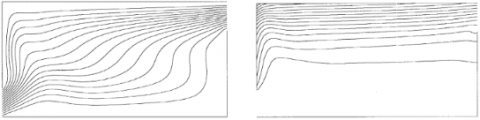
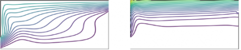
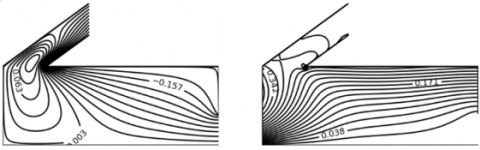
A uniform mesh of dimensions $101 \times 91$ and a time step of $\Delta t=5 \times 10^{-5}$ are used. The convergence criterion is based on a relative error of $10^{-5}$ calculated between two successive iterations. With these parameters, the present code is then tested under the working conditions of Raji and Hasnaoui [41], who studied mixed convection in a cavity with two apertures. In their study, the top and left vertical walls are subjected to a constant heat flux. Figure 2 presents the comparison and good agreement of the thermal and flow field results for Ra = 106 and Re = 100.
Figure 2. Diagram of streamline (left) and isotherms (right) for Re = 100 and Ra = 106: (a) comparison between the numerical results reported by Raji and Hasnaoui [41] and (b) those obtained using the present computational code
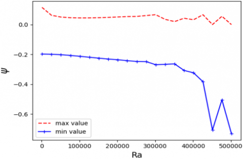
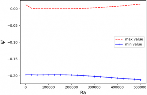
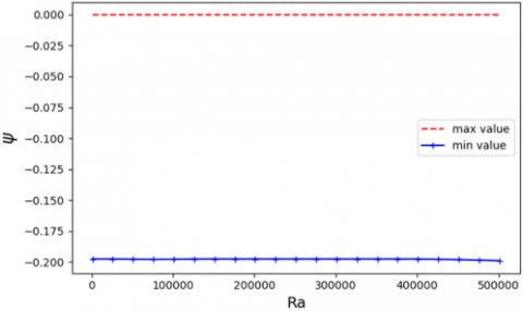
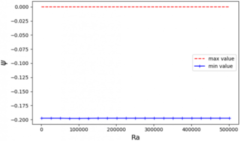
Figure 3. Extreme values of stream function
3.2 Discussions
The calculation conditions are summarized in Table 1.
Table 1. Computational parameters
|
Parameter |
Definition |
Value |
|
Dimensionless length |
L/L |
1 |
|
Dimensionless height |
h/L |
0.5 |
|
Dimensionless inflow port |
d/L |
0.2 |
|
Dimension air gap |
e/L |
0.03 |
|
Dimensionless length of PV |
LPV/L |
0.2 |
|
Absorptivity of the glazing |
αgl |
0.0014 |
|
Transmissivity of glazing |
τPV |
0.9 |
|
Absorptivity of the PV |
αPV |
0.9 |
|
Reference efficiency |
$\eta_{\text {ref}}$ |
0.125 |
|
Temperature coefficient |
$\beta_{\mathrm{PV}}$ |
0.0044℃-1 |
|
Temperature reference |
Tref |
25℃ |
|
Solar irradiance |
$\gamma$ |
0 |
3.2.1 Extreme values of stream function
The strictly positive or negative values of the stream function indicate a unidirectional flow. While vortices may be present, they evolve in the same direction as the main flow. The curves (see Figure 3) representing the extreme values (minimum and maximum) of the stream function, plotted as a function function of the Ra for a fixed Re , show that for $\mathrm{Re}<45$, reverse flows occur. In contrast, for $\operatorname{Re} \geq 45$, the flow direction remains unique regardless of Ra , since $\Psi_{\max }=0$. However, these results are not sufficient to conclude that the streamlines are entirely open or that no vortices exist, even when the flow appears unidirectional. Indeed, a domain entirely traversed by open streamlines implies a complete and continuous renewal of air within the region - an assertion that cannot be confirmed without further analysis.
3.2.2 Streamline and isotherms
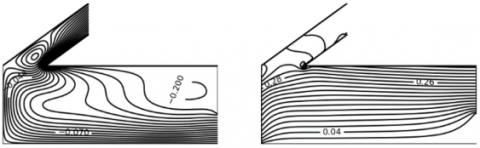
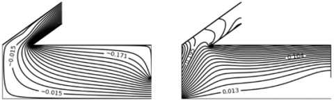
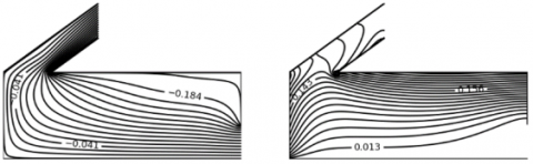
To visualize the real nature of the flow, it is essential to plot the streamlines that depict the movement of air from its entry into the cavity to its exit through the chimney. Forced convection develops with the increase in the Reynolds number (Re), which reflects the increase in the fan speed. Accordingly, Figures 4 to 9 illustrate the flow topology via streamlines (on the left), as well as the temperature distribution through isotherms (on the right).
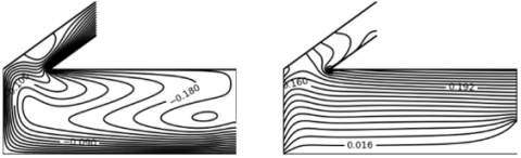
For low Reynolds number (Re < 45), natural convection dominates, leading to the formation of convective cells. This behavior is particularly observed for Re = 20 and Ra = 10³ (Figure 4(a)), where a convective cell appears near the hot left vertical wall.
Figure 4. Streamline (left) and isotherms (right) plots for Re = 20
Due to the suction effect exerted by the fan, this cell is drawn toward the chimney inlet, which it tends to obstruct. However, in accordance with the principle of mass conservation, the fresh air flow entering the cavity bypasses the convective cell by flowing along the upper horizontal wall to reach the chimney inlet, where it makes its way out.
The associated thermal field reveals isotherms that are generally parallel to the horizontal wall, but with a marked depression toward the left vertical wall. As a result, in the highly heated region located beneath the chimney, the temperature distribution becomes non-stratified, in contrast to the rest of the domain, where thermal stratification persists.
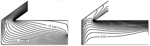
When Ra = 5 × 10⁴ (Figure 4(b)), the streamlines emerging from the inlet are deformed by thermal buoyancy and adopt a "Z"-shaped pattern. As the incoming airflow gradually heats up, it tends to fill the entire cavity volume, leading to the disappearance of the initially present convective cell. The deformation of the isotherms within the cavity becomes very slight, indicating a stratified temperature distribution, including in the area below the chimney. In this regime dominated by natural convection, the flow structure evolves into a large counterclockwise-rotating convective cell when Ra = 5 × 10⁵ (Figure 4(c)). Below the chimney, the isotherms show a hump-shaped deformation.
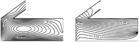
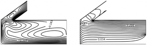
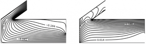
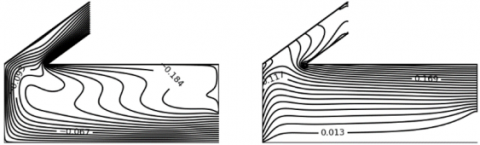
Figure 5. Streamline (left) and isotherms (right) plots for Re = 30
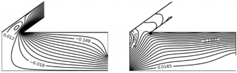
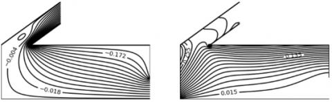
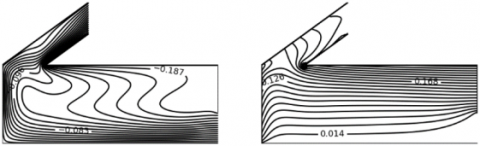
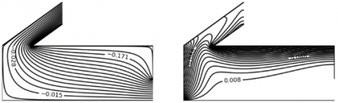
Figure 6. Streamline (left) and isotherms (right) plots for Re = 35
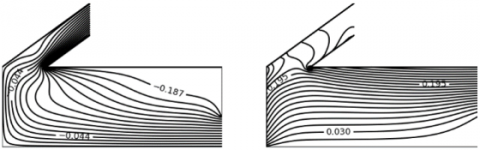
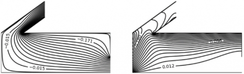
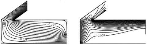
As the Reynolds number increases, the rotating cells are progressively weakened and eventually disappear entirely beyond Re = 45 (Figures 5 and 6). At this stage, the entire domain is characterized by open streamlines (Figures 7 to 9). Heat transfer then becomes dominated by forced convection, and the incoming fresh air flows directly toward the opposite vertical wall, bypasses it, and subsequently enters the chimney.
Within the chimney, the streamlines run parallel to the walls. The fluid undergoes a marked acceleration toward the outlet, as fluid particles are increasingly influenced by kinetic impulses acting parallel to the chimney walls. Nevertheless, the residual buoyancy forces at Ra = 5 × 10⁵ generate an upward motion of the air entering the cavity, resulting in a "Z"-shaped deformation of the streamlines (Figures 7(c) and 8(c)).
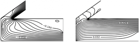
Figure 7. Streamline (left) and isotherms (right) plots for Re = 45
Figure 8. Streamline (left) and isotherms (right) plots for Re = 50
The corresponding isotherms accumulate along the horizontal wall, forming a clearly visible thermal boundary layer. The hump-shaped deformation of the isotherms at the chimney inlet becomes increasingly pronounced. This structure indicates good air renewal within the domain, while only the areas near the active walls retain a high temperature.
It is generally observed that, in the chimney (Figures 4 to 9), the isotherms are widely spaced, indicating the presence of weak temperature gradients.
Figure 9. Streamline (left) and isotherms (right) plots for Re = 100
3.2.3 Mean values of dimensionless temperature and Nusselt number
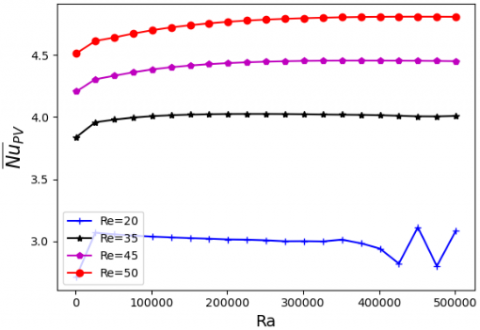
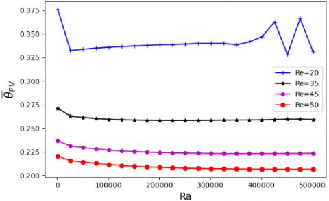
Figure 10 highlights an intensification of heat exchange between the fluid and the active surfaces, particularly the photovoltaic (PV) panel, as the Rayleigh number increases. This enhancement promotes the development of buoyancy forces, which induce an upward motion of the fluid and improve its mixing. These forces also cause thermal instabilities, manifested through recirculating flow patterns. The emergence and disappearance of convective cells may thus account for the observed fluctuations in the average Nusselt number in the case where Re = 20, a regime in which natural convection dominates the overall heat transfer mechanism. This result is consistent with the findings of Saha et al. [42], who reported similar behavior when increasing the Richardson number at a fixed Reynolds number. Furthermore, the increase in the Reynolds number provides additional kinetic energy to the hot, low-density fluid particles, accelerating their movement toward the chimney outlet. As a result, heat transfer is significantly enhanced with rising Reynolds number, emphasizing the increasing role of forced convection in the overall transfer process. This leads to an increase in the average Nusselt number and a corresponding decrease in the temperature of the PV panel, as shown in Figure 11. The principle of mass conservation ensures that the hot air evacuated through the chimney is generally replaced by cooler air entering the cavity through the opening on the right vertical wall. Consequently, the temperature within the living space decreases significantly with increasing Reynolds number, as illustrated in Figure 12.
Figure 10. Average Nusselt number calculated on PV
Figure 11. Dimensionless average temperature of the PV
Figure 12. Dimensionless average temperature of the fluid in the living space
3.2.4 Energy efficiency
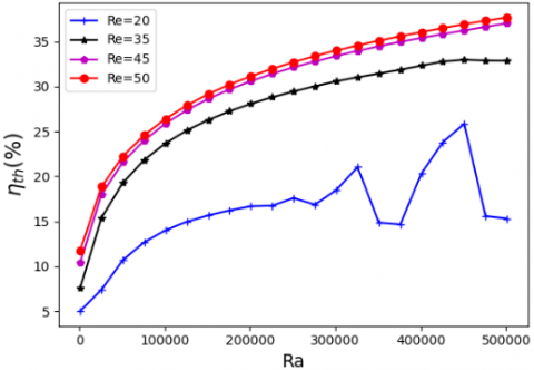
Figure 13 shows the thermal efficiency of the chimney as a function of the Rayleigh (Ra) and Reynolds (Re) numbers. It is observed that the efficiency increases with both parameters. Despite the relatively low values of Ra and Re, a satisfactory performance is achieved $\left(\eta_{\mathrm{el}}=38 \%\right.$ for $\mathrm{Re}=50$ and Ra $=5 \times 10^5$). This represents a significant improvement compared to the $30 \%$ efficiency obtained by Ong and Chow [28] under conditions of a 0.1 m air gap and a heat flux of $200 \mathrm{~W} / \mathrm{m}^2$ (i.e., a Rayleigh number $\mathrm{Ra} \approx 4 \times 10^6$). The oscillations observed for the case where Re = 20 indicate the presence of recirculating flow structures, which hinder the continuous renewal of the fluid, especially when heat transfer is primarily driven by natural convection. These oscillations progressively vanish as the Reynolds number increases, confirming that the addition of kinetic momentum to fluid particles, already subject to buoyancy forces, promotes a more stable flow and enhances continuous fluid renewal within the chimney.
Figure 13. Thermal efficiency
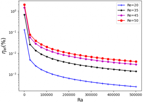
Figure 14. Electrical energy conversion efficiency
Figure 14 illustrates the conversion efficiency of the electrical energy generated by the photovoltaic panel into the kinetic energy of the fan. We evaluated the efficiency using the reference length L = 4 m, the PV length LPV = 1.6 m, and the air gap e = 0.12 m. It is important to note that we have used a logarithmic scale.
The conversion efficiency is very low, indicating that the fan consumes only a small fraction of the electrical energy produced by the PV panel. As expected, the efficiency increases with the Reynolds number, since higher kinetic energy corresponds to greater electrical energy consumption by the fan. For the considered values of Reynolds and Rayleigh numbers, the fan's electrical consumption represents between 10-4 and 2% of the electrical power produced by the PV panel. However, the efficiency decreases as the Rayleigh number increases. The reason for this behavior is that the fan operates at low power, with its maximum output occurring at low Ra, corresponding to low solar radiation. This observation aligns with the results reported by Klimeš et al. [22]. Furthermore, the fluid velocity at the chimney outlet remains constant for a given Reynolds number, according to Eq. (10). Therefore, the PV panel generates more energy than is consumed by the fan. The surplus energy can be used for other purposes or stored for later use.
This study benefits from a comprehensive approach that integrates the analysis of both the chimney and the building.
The numerical results of mixed convection obtained from a Fortran code based on the Gauss-Seidel algorithm show that:
Consequently, the photovoltaic chimney constitutes an effective solution for building cooling.
|
$\overrightarrow{\mathrm{e}_{\mathrm{x}}}, \overrightarrow{\mathrm{e}_{\mathrm{z}}}$ |
horizontal and vertical axis |
|
$\overrightarrow{\mathrm{V}}$ |
dimensionless velocity vector |
|
L |
length of the cavity, m |
|
Nu |
local Nusselt number along the PV |
|
Pe |
Péclet number |
|
t |
dimensionless time |
|
T |
temperature, K |
|
u,v |
horizontal and vertical velocity dimensionless velocity coordinate |
|
x, z |
horizontal and vertical dimensionless coordinates |
|
Greek symbols |
|
|
$\alpha$ |
thermal diffusivity, m2. s-1 |
|
$\beta$ |
thermal expansion coefficient, K-1 |
|
$\lambda$ |
thermal conductivity W.K-1. s-1 |
|
$\Omega$ |
dimensionless vorticity |
|
$\psi$ |
dimensionless stream function |
|
$\Phi_i$ |
Intensity of solar radiation, W m-2 |
|
$\theta$ |
dimensionless temperature |
|
v |
kinematic viscosity, m2.s-1 |
|
Subscripts |
|
|
f |
fluid |
|
p |
wall |
|
out |
outlet |
|
in |
inlet |
[1] Lam, J.C., Tsang, C.L., Li, D.H., Cheung, S.O. (2005). Residential building envelope heat gain and cooling energy requirements. Energy, 30(7): 933-951. https://doi.org/10.1016/j.energy.2004.07.001
[2] Omrany, H., Ghaffarianhoseini, A., Ghaffarianhoseini, A., Raahemifar, K., Tookey, J. (2016). Application of passive wall systems for improving the energy efficiency in buildings: A comprehensive review. Renewable and Sustainable Energy Reviews, 62: 1252-1269. https://doi.org/10.1016/j.rser.2016.04.010
[3] Xiong, L., Wang, M., Mao, J., Huang, B. (2024). A review of building carbon emission accounting methods under low-carbon building background. Buildings, 14(3): 777. https://doi.org/10.3390/buildings14030777
[4] Wang, G., Luo, T., Luo, H., Liu, R., Liu, Y., Liu, Z. (2024). A comprehensive review of building lifecycle carbon emissions and reduction approaches. City and Built Environment, 2(1): 12. https://doi.org/10.1007/s44213-024-00036-1
[5] Min, J., Yan, G., Abed, A.M., Elattar, S., Khadimallah, M.A., Jan, A., Ali, H.E. (2022). The effect of carbon dioxide emissions on the building energy efficiency. Fuel, 326: 124842. https://doi.org/10.1016/j.fuel.2022.124842
[6] Flores, R., Houssainy, S., Wang, W., Cu, K.N., Nie, X., et al. (2024). Addressing building related energy burden, air pollution, and carbon emissions of a low-income community in Southern California. Advances in Applied Energy, 14: 100169. https://doi.org/10.1016/j.adapen.2024.100169
[7] Mneimneh, F., Ghazzawi, H., Ramakrishna, S. (2023). Review study of energy efficiency measures in favor of reducing carbon footprint of electricity and power, buildings, and transportation. Circular Economy and Sustainability, 3(1): 447-474. https://doi.org/10.1007/s43615-022-00179-5
[8] Simona, P.L., Spiru, P., Ion, I.V. (2017). Increasing the energy efficiency of buildings by thermal insulation. Energy Procedia, 128: 393-399. https://doi.org/10.1016/j.egypro.2017.09.044
[9] Zou, D., Sun, C. (2020). Environmental thermal performance of prefabricated buildings based on building wall energy-saving technology. International Journal of Sustainable Development and Planning, 15(6): 965-969. https://doi.org/10.18280/ijsdp.150621
[10] Okokpujie, I.P., Essien, V., Ikumapayi, O.M., Nnochiri, E.S., Okokpujie, K., Akinlabi, E. (2022). An overview of thermal insulation material for sustainable engineering building application. International Journal of Design & Nature and Ecodynamics, 17(6): 831-841. https://doi.org/10.18280/ijdne.170603
[11] Campiotti, C.A., Gatti, L., Campiotti, A., Consorti, L., De Rossi, P., et al. (2022). Vertical greenery as natural tool for improving energy efficiency of buildings. Horticulturae, 8(6): 526. https://doi.org/10.3390/horticulturae8060526
[12] Ghasaban, M., Mirjalili, P., Yeganeh, M. (2025). Integration of building envelope with open spaces and greenery to enhance thermal and visual comfort and energy efficiency in office buildings. Results in Engineering, 25: 103660. https://doi.org/10.1016/j.rineng.2024.103660
[13] Liping, W., Angui, L. (2004). A numerical study of vertical solar chimney for enhancing stack ventilation in buildings. In Plea2004-the 21th Conference on Passive and Low Energy Architecture Eindhoven Netherlands, Eindhoven, the Netherlands, pp. 1-5.
[14] Zhai, X.Q., Song, Z.P., Wang, R.Z. (2011). A review for the applications of solar chimneys in buildings. Renewable and Sustainable Energy Reviews, 15(8): 3757-3767. https://doi.org/10.1016/j.rser.2011.07.013
[15] Miyazaki, T., Akisawa, A., Kashiwagi, T.J.R.E. (2006). The effects of solar chimneys on thermal load mitigation of office buildings under the Japanese climate. Renewable Energy, 31(7): 987-1010. https://doi.org/10.1016/j.renene.2005.05.003
[16] Harris, D.J., Helwig, N. (2007). Solar chimney and building ventilation. Applied Energy, 84(2): 135-146. https://doi.org/10.1016/j.apenergy.2006.07.001
[17] Bansal, N.K., Mathur, R., Bhandari, M.S. (1993). Solar chimney for enhanced stack ventilation. Building and Environment, 28(3): 373-377. https://doi.org/10.1016/0360-1323(93)90042-2
[18] Abdeen, A., Serageldin, A.A., Ibrahim, M.G., El-Zafarany, A., Ookawara, S., Murata, R. (2019). Solar chimney optimization for enhancing thermal comfort in Egypt: An experimental and numerical study. Solar Energy, 180: 524-536. https://doi.org/10.1016/j.solener.2019.01.063
[19] Belfegas, B., Larbi, S., Tayebi, T. (2021). Experimental and theoretical investigation on a solar chimney system for ventilation of a living room. Mathematical Modelling of Engineering Problems, 8(2): 259. https://doi.org/10.18280/mmep.080213
[20] Mathur, J., Mathur, S. (2006). Summer-performance of inclined roof solar chimney for natural ventilation. Energy and Buildings, 38(10): 1156-1163. https://doi.org/10.1016/j.enbuild.2006.01.006
[21] Ahmed, O.K., Hussein, A.S. (2018). New design of solar chimney (case study). Case Studies in Thermal Engineering, 11: 105-112. https://doi.org/10.1016/j.csite.2017.12.008
[22] Klimeš, L., Charvát, P., Hejčík, J. (2018). Comparison of the energy conversion efficiency of a solar chimney and a solar PV-powered fan for ventilation applications. Energies, 11(4): 912. https://doi.org/10.3390/en11040912
[23] Lare, D.Y., Nougblega, Y., Kpode, K., Amou, K.A. (2024). Enhancing thermoelectric efficiency through combined and shunt solar chimneys: An investigation of vented photovoltaic panels with multiple inlets. International Journal of Heat and Technology, 42(5): 1709-1720. https://doi.org/10.18280/ijht.420525
[24] Jiménez-Xamán, C., Xamán, J., Gijón-Rivera, M., Zavala-Guillén, I., Noh-Pat, F., Simá, E. (2020). Assessing the thermal performance of a rooftop solar chimney attached to a single room. Journal of Building Engineering, 31: 101380. https://doi.org/10.1016/j.jobe.2020.101380
[25] Wei, T., Li, H., Sun, R., Yu, C.W., Luo, X. (2024). Evaluation of photovoltaic-based solar chimney–assisted stack ventilation within a large space hall: A case study. Indoor and Built Environment, 33(4): 741-756. https://doi.org/10.1177/1420326X231220
[26] Ren, X.H., Wang, L., Liu, R.Z., Wang, L., Zhao, F.Y. (2021). Thermal stack airflows inside the solar chimney with discrete heat sources: Reversal flow regime defined by chimney inclination and thermal Rayleigh number. Renewable Energy, 163: 342-356. https://doi.org/10.1016/j.renene.2020.08.128
[27] Ren, X.H., Wang, P.L., Zhang, C.X., Song, Y.J., Shang, J., Wang, L., Zhao, F.Y. (2024). Heat removal and ventilation limitations of the solar chimney attached with a built enclosure: Correlations of thermal Rayleigh numbers, port arrangements and discrete heating elements. Renewable Energy, 221: 119782. https://doi.org/10.1016/j.renene.2023.119782
[28] Ong, K.S., Chow, C.C. (2003). Performance of a solar chimney. Solar Energy, 74(1): 1-17. https://doi.org/10.1016/S0038-092X(03)00114-2
[29] Nguyen, Y.Q., Wells, J.C. (2020). A numerical study on induced flowrate and thermal efficiency of a solar chimney with horizontal absorber surface for ventilation of buildings. Journal of Building Engineering, 28: 101050. https://doi.org/10.1016/j.jobe.2019.101050
[30] Jing, H., Chen, Z., Li, A. (2015). Experimental study of the prediction of the ventilation flow rate through solar chimney with large gap-to-height ratios. Building and Environment, 89: 150-159. https://doi.org/10.1016/j.buildenv.2015.02.018
[31] Lubis, I.H., Koerniawan, M.D. (2018). Reducing heat gains and cooling loads through roof structure configurations of a house in Medan. IOP Conference Series: Earth and Environmental Science, Bandung, Indonesia, 152: 012008. https://doi.org/10.1088/1755-1315/152/1/012008
[32] Adounkpe, J.G., Lawin, A.E., Ahouannou, C., Akiyo, R.O.L., Sinsin, B.A. (2013). Modeling solar energy transfer through roof material in Africa sub-Saharan regions. International Scholarly Research Notices, 2013(1): 480137. https://doi.org/10.1155/2013/480137
[33] Suehrcke, H., Peterson, E.L., Selby, N. (2008). Effect of roof solar reflectance on the building heat gain in a hot climate. Energy and Buildings, 40(12): 2224-2235. https://doi.org/10.1016/j.enbuild.2008.06.015
[34] Ostrach, S. (1988). Natural convection in enclosures. Journal of Heat Transfer, 110(4B): 1175-1190. https://doi.org/10.1115/1.3250619
[35] Kpode, K., Sow, M.L., Mbow, C. (2016). Unsteady natural convection with summer boundary conditions in a habitat at high Rayleigh number and at high time. Energy and Buildings, 121: 72-77. https://doi.org/10.1016/j.enbuild.2016.03.068
[36] Ren, X.H., Wang, L., Liu, R.Z., Wang, L., Zhao, F.Y. (2021). Thermal stack airflows inside the solar chimney with discrete heat sources: Reversal flow regime defined by chimney inclination and thermal Rayleigh number. Renewable Energy, 163: 342-356. https://doi.org/10.1016/j.renene.2020.08.128
[37] Klimeš, L., Charvát, P., Hejčík, J. (2018). Comparison of the energy conversion efficiency of a solar chimney and a solar PV-powered fan for ventilation applications. Energies, 11(4): 912. https://doi.org/10.3390/en11040912
[38] N’Tsoukpoe, K.E. (2022). Effect of orientation and tilt angles of solar collectors on their performance: Analysis of the relevance of general recommendations in the West and Central African context. Scientific African, 15: e01069. https://doi.org/10.1016/j.sciaf.2021.e01069
[39] Notton, G., Cristofari, C., Mattei, M., Poggi, P. (2005). Modelling of a double-glass photovoltaic module using finite differences. Applied thermal engineering, 25(17-18): 2854-2877. https://doi.org/10.1016/j.applthermaleng.2005.02.008
[40] Patankar, S. (2018). Numerical heat transfer and fluid flow. CRC Press. https://doi.org/10.1201/9781482234213
[41] Raji, A., Hasnaoui, M. (2000). Mixed convection heat transfer in ventilated cavities with opposing and assisting flows. Engineering Computations, 17(5): 556-572. https://doi.org/10.1108/02644400010339770
[42] Saha, S., Saha, G., Ali, M., Islam, M.Q. (2006). Combined free and forced convection inside a two-dimensional multiple ventilated rectangular enclosure. ARPN Journal of Engineering and Applied Sciences, 1(3): 23-35.