Ahmad Purnomo![]() | Zainal Arifin*
| Zainal Arifin*![]() | Rendy Adhi Rachmanto
| Rendy Adhi Rachmanto![]() | Singgih Dwi Prasetyo
| Singgih Dwi Prasetyo![]()
© 2025 The authors. This article is published by IIETA and is licensed under the CC BY 4.0 license (http://creativecommons.org/licenses/by/4.0/).
OPEN ACCESS
The demand for renewable energy sources continues to escalate as a means of addressing climate change. This study explores a novel approach to enhance the output power of floating photovoltaic (FPV) systems by integrating innovative multi-reflector systems with partially submerged staggered fin heat sinks. Increasing solar irradiation typically boosts the energy output. It simultaneously raises the panels' temperature, which can detract from overall performance. Our research employs multi-reflector designs to concentrate solar irradiation on FPV panels while utilizing partially submerged fin heat sinks to optimize heat dissipation. Experimental tests conducted in Surakarta, Indonesia, starting at 8 am and continuing until 4 pm involved three unique reflector configurations and two heat sink designs. Results indicated a significant increase in output power by integrating a reflector 1.25 times the panel width with a partially submerged staggered fin heat sink design, with a rise of 7.28 watts—or 17.17%—compared to a conventional floating photovoltaic. Statistical analysis via two-way ANOVA affirmed the effectiveness of both design variations in enhancing power output. This research represents an advancement in FPV technology, demonstrating that the application of reflectors and advanced heat sinks can improve energy production while maintaining lower operating temperatures, thereby providing a sustainable solution.
floating photovoltaics, multi-reflector systems, heat sink technology, renewable energy efficiency, solar energy concentration, temperature management, energy sustainability, ANOVA statistical analysis
In today’s era, the need for energy is increasing. The supply of fossil fuels has decreased as a result of this demand. As a result, switching from non-renewable to renewable energy is essential [1]. Renewable energy sources including solar, wind, and geothermal have grown faster and the studies on the use of renewable energy such as PV wind turbines [2, 3] continue to develop over time. Solar energy is a far more abundant renewable energy source, ranking third in importance for heating and lighting. Solar energy is the most promising way to meet the world's expanding energy needs because it is readily available and emits no greenhouse gases [4]. The importance of renewable energy lies in its role in ensuring long-term energy sustainability and meeting climate goals. By utilizing renewable energy, the energy supply can transition from fossil fuels to more sustainable energy sources [5]. Photovoltaic panels are the most suitable technology for capturing solar energy. In Indonesia, the average solar energy intensity is 4.7 to 4.8 kWh/m² [6, 7]. Typically, just a small amount of the solar irradiation is absorbed by photovoltaic solar panels and transformed into electrical energy, the remainder is absorbed as heat [8].
There are three generations of photovoltaic panels: Silicon photovoltaic cells made with silicon layers, the second generation referring to thin-film technology, and Dye Sensitized Solar Cell (DSSC) designed using environmentally friendly materials such as natural dyes [9]. Silicon photovoltaic cells are the most commonly utilized type of PV cells. The efficiency generated is greater than that of others. The efficiency of this monocrystalline silicon PV cell is approximately 17% to 18%. The polycrystalline type exhibits an efficiency ranging from approximately 12% to 14% [10]. The temperature of photovoltaic panels and sun irradiation are two aspects that influence them. The power output of the PV module increases in direct correlation to the solar energy it absorbs. Higher peaks on the power output curves signify that the photovoltaic module may generate increased electricity with the rise in solar radiation [11].
Rahman et al. [12] determined that a rise in irradiation of 100 W/m2 resulted in an enhancement of energy output by 2.94 W. A method used to enhance the absorption of solar irradiation on photovoltaic solar panels is by integrating a reflector [13]. Reflectors are a cost-effective optical device technology, with expenses not surpassing 5% of the photovoltaic module cost. They are designed to concentrate light and enhance the sunlight exposure on photovoltaic panels [14]. There are various types of reflectors that exist, such as the flat plate reflectors, the parabolic reflectors, and the polyline reflectors [15]. Reflectors are fabricated from various reflective materials to reflect the solar beam [16], such as glass mirrors, aluminum foil, and aluminum sheets.
Research indicates that the implementation of a single-sided polyline reflector can enhance solar irradiation on the collector by 40.3% [17]. Utilizing reflectors also enhances the electricity generation capacity of photovoltaic panels [18]. Single-sided reflectors on photovoltaic panels enhance power output by 10-13% during winter and 11-19% in summer, specifically in Western Himalayan climates [19]. Rachedi et al 's simulation findings reveal that the use of 4-sided reflectors can improve the mean yearly irradiation by 64% for fixed systems and by 111.28% for solar tracker systems. The daily average benefit ratio of the experimental receiving solar irradiation is measured at 1.33 and 4.25, respectively [20].
The performance of photovoltaic solar panels is negatively affected by high temperatures [21], while increased solar radiation boosts energy output. Therefore, it is crucial to keep the temperature of the photovoltaic solar panels low and to maximize solar radiation absorption [22]. Advancements in photovoltaic cooling methods have been persistently pursued. Cooling is accomplished through the use of fluids directed at the PV system, either directly, like water spray [23] and floating methods [24], or indirectly by heat sink system [25] and photovoltaic thermal collectors [26]. An increase in temperature leads to a decrease in the voltage produced by photovoltaic panels. With each degree Celsius increase in temperature, the voltage of the PV panel decreases by approximately 2.2 mV, leading to a reduction in power output of around 0.5% [11, 27].
Research indicates that floating photovoltaics can achieve a cooling effect on the panel's surface temperature of 2-4% and generate more power than non-floating photovoltaics [28]. Floating photovoltaics utilizing PV panels in direct contact with the membrane in the water body provide 5-7% greater electricity compared to those without direct touch [29]. A natural convection cooling system for floating photovoltaics has been proposed, demonstrating that a thermosiphon system achieves greater efficiency compared to floating photovoltaics without cooling mechanisms [30]. Adjusting the water reservoir height to 750 mm achieved an efficiency increase of 17.84% [31]. Floating photovoltaics, where the panel area is partially submerged in a body of water, have the ability to enhance electricity production [32]. By adding fin heatsinks on the panel's back surface, the temperature can be lowered by 19.07%, power output can be increased by 24.02%, and efficiency can be increased by 22.24% [33]. Meanwhile, using forced convection cooling, it was found that adding fin heat sinks to the photovoltaic panel that are partially submerged in the water body may cut operating temperatures by 33.31% and boost productivity by 22.77% [34].
According to earlier studies, conventional FPV exhibit elevated operating temperatures and reduced efficiency compared to FPV equipped with cooling systems. There are limitations to PV panel cooling technology that involves directly immersing the panels in water, as this can cause algae growth on the panel surface in the long term. At present, the use of fin heatsink technology for natural cooling, without the immersion of panels in floating photovoltaic systems, yields low enhancements in power output. The integration of multi-reflectors is advantageous for increasing solar radiation absorption and can enhance power productivity.
Based on the previously mentioned study, there is a notable research gap that presents an opportunity for novelty, specifically the integration of multi-reflectors as irradiation concentrators alongside partially submerged fin heat sinks as cooling mechanisms in floating photovoltaic systems. Reflectors are expected to increase the absorption of solar irradiation, and the heatsink cooling mechanism is expected to optimise heat dissipation to mitigate the harmful impacts of the panel's excessive heat. Moreover, it is expected that this technology will improve the performance of photovoltaic panels.
This document is structured into multiple sections. The initial section presents the study and delineates its aims. The second section outlines the methodology employed in the study, encompassing the tools utilized and the analytical techniques applied. The third section outlines the experimental outcomes for each variation, accompanied by a discussion informed by ANOVA analysis. In conclusion, the paper provides a summary of the findings employing the multi-reflector designs to concentrate solar radiation on FPV panels and utilizing partially submerged fin heat sinks to optimize heat dissipation based on experimental investigation and outlines recommendations for future investigations.
2.1 Experimental setup
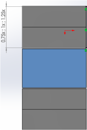
This study examines the potential to enhance the output power of solar panels. Additionally, in relation to environmental concerns, solar energy and renewable energy sourced directly or indirectly from the sun may be considered. Subsequent research involved an addition of reflectors to amplify solar irradiation intensity and the installation of a partially submerged fin heat sink aluminum plate on the rear of the solar panel for improved cooling, therefore mitigating the impacts of the added reflectors. The three analyzed geometric shapes of the reflectors were 0.75, 1, and 1.25 times the width of the photovoltaic panel, arranged in a top-bottom configuration, with each side comprising two combined reflectors. These variations are designated as reflector variation 1, reflector variation 2, and reflector variation 3. The installation of the reflector establishes a 120-degree angle, identified as the optimal angle according to research conducted by Manosroi et al. [35]. The reflector is constructed from aluminum due to its lightweight properties and possesses a reflectance rating of around 0.950-0.980 [36]. Figure 1 illustrates the reflectors employed in this investigation for each geometric design.
Figure 1. The reflector geometri with ratio 0.75; 1; 1.25 times wide of pv panel
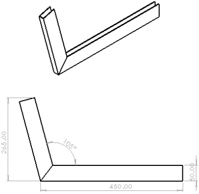
(a) Solid heatsink
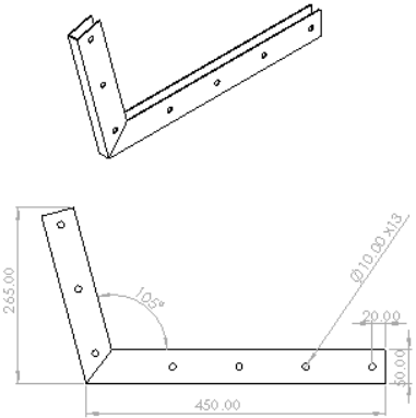
(b) Staggered perforated heatsink
Figure 2. The heatsink geometry for each shape
Two distinct fin heatsink geometries, each consisting of 12 fins, were utilized to attain optimal cooling performance in the photovoltaic system. The geometric forms of the fin heatsink analyzed consist of a solid heatsink, referred to as heatsink variation 1, and a staggered perforated heatsink, designated as heatsink variation 2. The height of each fin heatsink is set at 50 mm, a specification derived from the optimal performance range of 50-100 mm, as indicated in the research conducted by Nižetić et al. [37]. The fin heatsinks were constructed from aluminum, selected for its lightweight properties, high thermal conductivity, and cost-effectiveness. Figure 2 illustrates the fin heatsinks utilized in this study corresponding to each geometric configuration. The research was carried out on a floating photovoltaic system. Tarpaulin was used to construct a tube water basin with a diameter of 2 meters and a water depth of 1.1 meters. The purpose of this basin was to simulate a body of water in which the FPV modules act as a natural sink, allowing the modules to expel any excess heat that they generate through the use of extended submerged fins.
The increase in solar irradiation intensity incident on the solar panel is achieved while maintaining the panel temperature at a reduced level, which subsequently enhances the power output of the photovoltaic panel.
This experiment was conducted atop the UNS INN Building at Sebelas Maret University, Central Java, Indonesia. The panel was oriented northward at a 12-degree angle for the tests conducted from 8:00 am to 4:00 pm. Reflectors are attached to both the top and bottom sides of the photovoltaic (PV) system, while finned heat sinks have been included into the back panel. This study used a 50Wp polycrystalline photovoltaic panel manufactured by Jolywood Suzhou Sunwatt Co. Ltd. The specifications of the utilized photovoltaic panels are detailed in Table 1.
Table 1. SunWatt 50Wp specifications photovoltaic panel
|
Specifications |
Information |
|
Type |
Polycrystalline |
|
VOC |
21.24 V |
|
ISC |
3.11 A |
|
PMAX |
50 W |
|
Efficiency |
17.6 % |
|
Operating temperature |
-40℃ s/d 85℃ |
|
Dimensions in mm |
670×530×30 (4,23kg) |
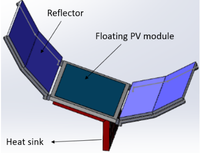
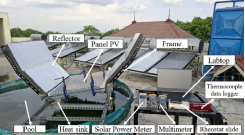
K-type thermocouple sensors were used to measure the temperature, and a LabJack U6 data logger was used to store the data. Nine temperature sensors were affixed to the panel's surface. Solar irradiation was quantified with a Lutron SPM-1116SD solar meter. A Heles UX838-TR multimeter was used to measure the output power, which was made up of voltage and current from the solar panel. A rheostat was used to apply a load. Figure 3 illustrates the design of FPV and the experimental figure, encompassing the arrangement of instruments. Table 2 presents the specs and accuracy of the measuring instruments utilized.
(a)
(b)
Figure 3. (a) The FPV design, (b) Experimental setup
Table 2. Specs and accuracy of the measuring instruments [38]
|
Instruments |
Model |
Specifications |
|
Multimeter |
Heles UX838-TR |
Accuracy: ±3% for DC current and ±0.5% for DC voltage |
|
Thermocouples |
K-Type |
Accuracy: ± 2.2℃ Range: –270 to 1260℃ |
|
Solar power meter |
Lutron SPM 1116SD |
Accuracy: ±5% Range: 0-2000 W/m2 |
2.2 Work parameter analysis
This study evaluates the solar panel's performance throughout several combinations of reflector and fin heatsink installations. Data on temperature and solar irradiation for each test were collected at nine points, and the mean value was computed to elucidate each variation. The power output performance of the PV panel is generally depicted as a correlation between current and voltage in the format of an I-V graph. A rheostat was utilized to produce changes in resistance to achieve this graph. The characterization of photovoltaic panels through the measurement of I-V graphs seeks to yield various parameters, such as Voc, Isc, fill factor (FF), and efficiency (η). The open circuit voltage (Voc) represents the maximum voltage attained in the absence of current flow within the circuit. The short circuit current (Isc) represents the maximum current achieved when no resistance exists. The maximum power point (PMPP) is a point on the I-V curve that yields the highest product of current and voltage in the circuit. The fill factor (FF) is the ratio of the PMPP to the product of Voc and Isc on the I-V graph. The correlation between all these parameters is outlined in Eq. (1) below [38].
$F F=\frac{P_{M P P}}{I s c \times V o c}=\frac{I_{M P P} \times V_{M P P}}{I s c \times V o c}$ (1)
Energy efficiency (η) is the ratio of the maximum power point to the energy from solar radiation that solar PV captures (Ilight). The maximum power point (PMPP) is calculated by multiplying the open-circuit voltage, short-circuit current, and fill factor. The calculation of solar radiant power (Ilight) involves multiplying the intensity of solar irradiation (Irad) by the area (A) of the active region of the solar cell. The panel's efficiency can be determined using Eq. (6) [38].
$\eta=\frac{P_{M P P}}{I_{\text {light}}}=\frac{P_{M P P}}{I_{\text {rad}} \times A}=\frac{I s c \times V o c \times F F}{I_{\text {rad}} \times A}$ (2)
2.3 Research stage
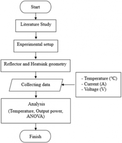
This study employs statistical analysis, as illustrated in Figure 4, to assess the significance of the results and evaluate the influence of the two dependent variables on the independent variable. For statistical analysis, this study used a two-way ANOVA without replication. The choice of ANOVA is grounded in the observation that the data consists of a singular dataset comprising values from two groups of dependent variable data, namely the geometric shape of the reflector and the geometric shape of the fin heatsink. ANOVA offers insights into the significance level of the differences among the data groups under examination. Establishing the initial hypothesis and the significance value to be assessed is essential in the preliminary preparation; a significance level of 0.05 is employed to determine the differences in data.
Figure 4. Research flowchart [39]
The independent variable in this study is the enhancement of output power. The hypothesis determination involves analyzing the impact of the reflector's geometric shape and the fin heat sink's geometric shape on output power enhancement. The null hypothesis (H₀) and alternative hypothesis (H₁) for each variable in this study are defined as follows:
2.3.1 Independent variable: Output power
H₀: There is no significant effect of the reflector's geometric shape on the output power of the photovoltaic panel.
H1: The reflector's geometric shape significantly affects the output power of the photovoltaic panel.
H₀: There is no significant effect of the fin heat sink's geometric shape on the output power of the photovoltaic panel.
H1: The fin heat sink's geometric shape significantly affects the output power of the photovoltaic panel.
3.1 The effect of adding reflectors on increasing the intensity of solar radiation
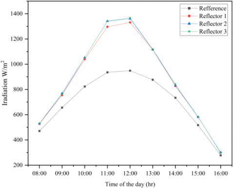
The amount of sunlight absorbed by photovoltaic panels affects their performance. It is necessary to have a high intensity of sun irradiation to guarantee that photovoltaic panels will work at their best [39]. The addition of reflectors to the photovoltaic panel is one method that may be utilized to increase the intensity of solar irradiation. Figure 5 illustrates that the addition of reflectors onto the photovoltaic panel can enhance the intensity of solar irradiation received. At noon, the solar irradiation intensity on the photovoltaic panel without a reflector was 948.9 W/m², whereas reflector 1 recorded 1331.3 W/m², reflector 2 recorded 1360.7 W/m², and reflector 3 recorded 1367.3 W/m². There is a rise in irradiation levels of 40.30%, 43.40%, and 44.10%, consistent with the study [17], which indicates a 40.30% increase in solar irradiation. The increase in solar irradiation at 08:00 and 16:00 is insignificant due to the reflection of solar irradiation not striking the surface of the photovoltaic panel.
Figure 5. Solar radiation intensity
3.2 Working temperature
3.2.1 Panel working temperature in reflector variation
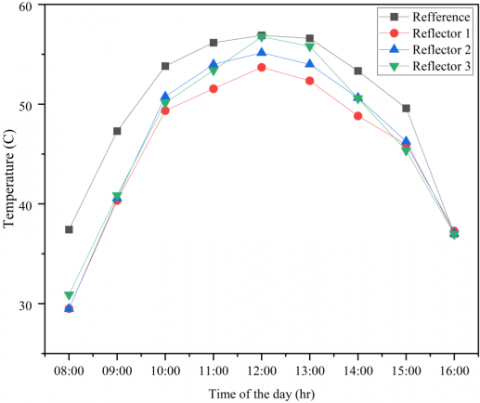
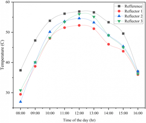
The proposed new reflectors are anticipated to enhance absorbed solar irradiation. Consequently, the experimental findings in this part encompassed the FPV module's operational temperature contingent upon the reflector's variation. Figure 6 presents the results of the tests conducted, indicating a rise in the average surface temperature of the panel corresponding to the increase in reflector variation. However, there is a decrease in the average surface temperature of the photovoltaic panel with each variation of the reflector shape compared to the average surface temperature of the reference panel; the rise in the panel's average surface temperature results from the solar panel's increased irradiation absorption. The reference panel's average surface temperature at noon was 56.9℃. The average surface temperatures of the photovoltaic panel with reflector variations on heat sink 1 are 53.69℃, 55.14℃, and 56.77℃. The average surface temperatures of the solar panel with reflector variations on heat sink 2 are 52.29℃, 54.62℃, and 56.04℃. Changes in reflector geometry affect the surface temperature of the photovoltaic panel, with larger reflector geometries leading to increased surface temperatures.
(a) Heat sink 1
(b) Heat sink 2
Figure 6. Working temperature reflects variation
3.2.2 Working temperature in the fin heat sink variation
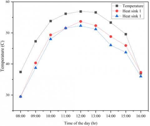
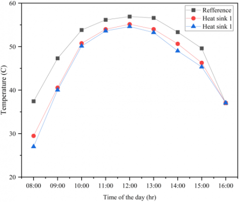
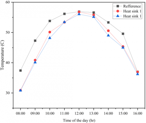
Figure 7 displays the test results, illustrating the geometric shape of the heat sink that contributes to a reduction in the surface temperature of the photovoltaic panel, as evidenced by the disparity in the average surface temperature of the photovoltaic panel relative to the reference conditions. At noon, the surface temperature of the reference panel attained 56.9℃. The surface temperatures of the solar panel on reflector 1 were 53.69℃ and 52.29℃. A temperature reduction of 1.4℃ is seen between heatsinks 1 and 2. The surface temperature of the panel on reflector 2 is 55.14℃ and 54.62℃, indicating a temperature drop of 0.52℃ between heatsinks 1 and 2. The panel temperature on reflector variation 3 was 56.77℃ and 56.04℃. The temperature reduction between heatsinks 1 and 2 is 0.73℃. Heatsink geometry 2 demonstrates superior heat dissipation compared to heatsink geometry 1.
The movement of air plays a crucial role in how heat is released [34]. The existing studies show that forced convection, affected by the intensity and direction of wind, provides improved heat transfer in comparison to natural convection [40, 41]. The results of the present investigation are aligned with those of Tijani et al, which indicated that the Nusselt number for perforated pin fins under forced heat transfer is generally higher by as much as 4% in comparison to solid fins [42]. At Re = ~ 2550–12,860, the Longitudinal Hole and Lateral & Longitudinal Hole types of pin fins demonstrate an increase in Nu avg by 22% and 20%, respectively, when compared to the conventional solid elliptical pin fin configuration [43]. Consequently, significant progress was achieved in minimizing the hot spot across the panel surface, which could potentially result in decreased efficiency or permanent damage, while also successfully meeting the objective of controlling the module's operating temperature.
(a) Reflector 1
(b) Reflector 2
(c) Reflector 3
Figure 7. Working temperature in the fin heat sink variation
3.3 Electrical analysis
3.3.1 Photovoltaic electric performance in reflector variation
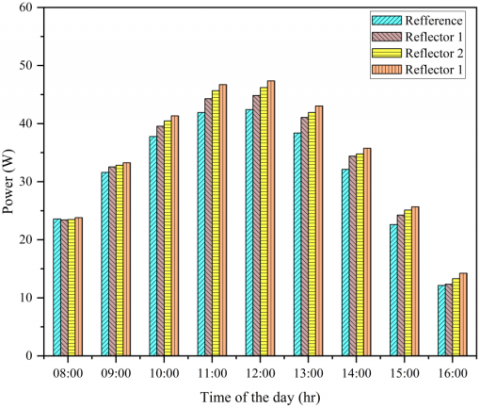
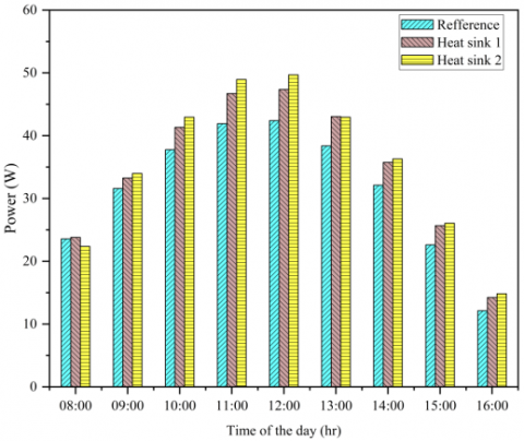
As in previous research, when solar intensity escalates, there is an increase in the maximum power produced by the photovoltaic panel [44]. Figure 8 illustrates the power output of solar panels with different reflector geometries. The findings indicate that an increase in the reflector geometry variation relates to a higher power output achieved. The reference photovoltaic panel achieved a power output of 42.40 Watts at peak intensity during the day. In comparison, the photovoltaic panel with reflector variations on the heat sink recorded power outputs of 44.84 Watts, 46.20 Watts, and 47.36 Watts at the same peak intensity, reflecting increases of 5.75%, 8.96%, and 11.70% respectively. In the meantime, the power output of the solar panel photovoltaic with reflector variations on heat sink 2 was measured at 46.90 Watts, 48.51 Watts, and 49.68 Watts, reflecting increases in power output of 10.61%, 14.41%, and 17.17% respectively.
(a) Heat sink 1
(b) Heat sink 2
Figure 8. The power output of FPV on reflector geometry variations
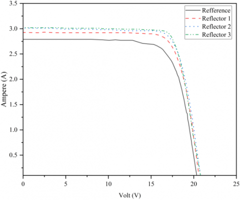
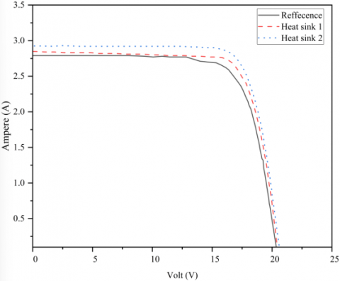
The graph illustrating the relationship between voltage and current is derived from integrating multiple data results. It demonstrates the correlation among voltage, current, and the resulting power. The test results indicated that the peak power output occurred at noon, which was subsequently utilized as a measurement parameter for constructing the current-voltage graph. Figure 9 illustrates the I-V graph of photovoltaic panels, illustrating the effects of different reflector geometries.
Figure 9 illustrates the correlation of the photovoltaic panel performance parameters at noon. The reference photovoltaic panel generates an Isc of 2.79 A, while the photovoltaic panel with reflector variations on heat sink 1 yields Isc values of 2.85 A, 2.88 A, and 2.90 A. The photovoltaic panel with reflector variations on heat sink 2 achieves Isc values of 2.93 A, 3.01 A, and 3.02 A. The test results indicate that changes in reflector geometry influence the increase in Isc value. This aligns with the previous study [15], indicating that the Isc value will rise as the intensity of solar irradiation increases. Simultaneously, the reference photovoltaic panel generates a Voc of 20.4 V. The photovoltaic panel with reflector variations on heat sink 1 yields Voc of 20.5 V, 20.6 V, and 20.7 V, and the photovoltaic panel with reflector variations on heat sink 2 achieves Voc of 20.6 V, 20.8 V, and 20.8 V.
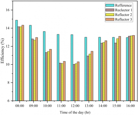
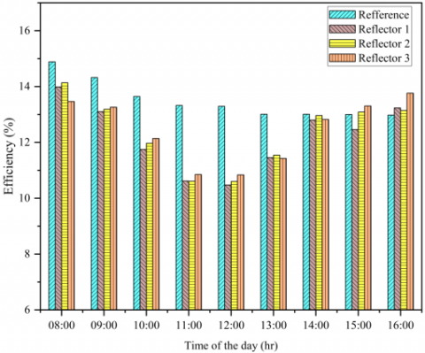
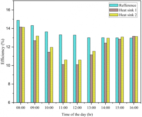
The findings regarding the efficiency calculations are illustrated graphically in Figure 10 of this study. The calculation of electrical efficiency for a photovoltaic panel involves contrasting the peak power (PMPP) with the radiation power the panel has received (Ilight), as outlined in Eq. (2); the result is displayed as a percentage. The daily electrical efficiency is illustrated in Figure 10. At noon, the reference photovoltaic panel was recorded to have an electrical efficiency of 13.29%. The efficiencies measured for the photovoltaic panel with reflector variations on heat sink 1 were 10.02%, 10.10%, and 10.30%. Conversely, the photovoltaic panel with reflector variations on heat sink 2 showed 10.48%, 10.60%, and 10.81% efficiencies. Adding reflector variations increases the solar irradiation received by the photovoltaic panel, reducing efficiency with each variation.
(a) Heat sink 1
(b) Heat sink 2
Figure 9. The I-V graph of FPV on reflector variation
(a) Heat sink 1
(b) Heat sink 2
Figure 10. The daily electrical efficiency of FPV on reflector variation
3.3.2 Photovoltaic electric performance in heat sink variation
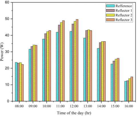
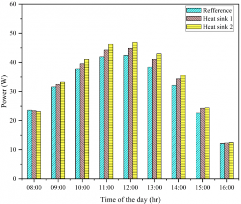
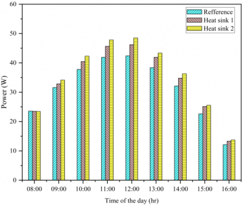
Figure 11 indicates that heat sink 1 yields a lower power output overall than heat sink 2. The reference photovoltaic panel generates a power output of 42.40 watts at peak intensity throughout the day. The power output of the photovoltaic panel with variations in the heat sink on reflector 1 at peak intensity is recorded at 44.84 Watts and 46.90 Watts, indicating an increase in power output of 5.75% and 10.61%, respectively. The photovoltaic panel, utilizing variations in the heat sink on reflector 2, generates power outputs of 46.20 watts and 48.51 watts, reflecting increases of 8.96% and 14.41%, respectively. When modified with variations in the heat sink on reflector 3, the photovoltaic panel yields power outputs of 47.36 watts and 49.68 watts, indicating increases of 11.70% and 17.17%, respectively.
(a) Reflector 1
(b) Reflector 2
(c) Reflector 3
Figure 11. The power output of FPV on heat sink geometry variations
(a) Reflector 1
(b) Reflector 2
(c) Reflector 3
Figure 12. The I-V graph of FPV on heat sink variation
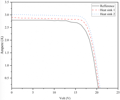
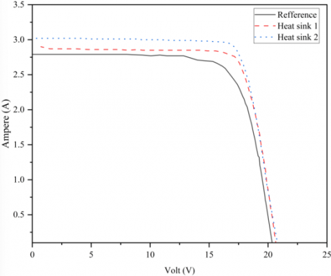
Figure 12 illustrates the correlation of the photovoltaic panel performance parameters at noon. The data indicates that the Isc value for heat sink 1 is consistently lower than that of heat sink 2 across all reflector variations. In reflector variation 1, the Isc values recorded are 2.85 A and 2.93 A. In reflector variation 2, the Isc values recorded are 2.88 A and 3.01 A, while in reflector variation 3, the Isc values are 2.90 A and 3.02 A. The Voc value for heat sink variation 1 is consistently lower than that of heat sink variation 2 across all tested variations. The Voc value on the photovoltaic panel, reflector variation 1, is recorded at 20.5 V and 20.6 V. The photovoltaic panel with reflector variation 2 shows Voc values of 20.6 V and 20.8 V, while the panel with reflector variation 3 displays Voc values of 20.7 V and 20.8 V.
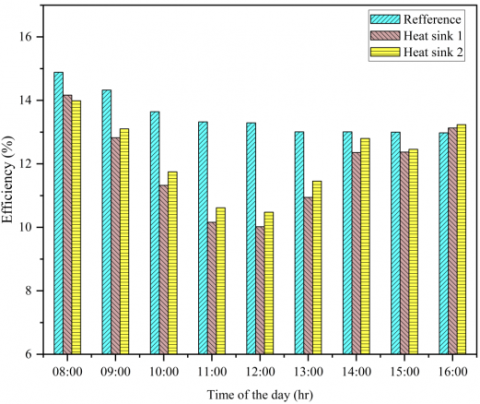
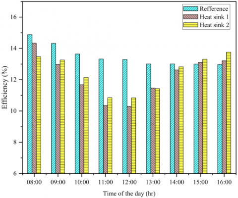
Figure 13 illustrates a graph depicting the correlation between variations in heat sink geometry and electrical efficiency. The graph illustrates the efficiency achieved by the photovoltaic panel over the day. At noon, the reference photovoltaic panel was recorded to have an electrical efficiency of 13.29%. PV panel electricity efficiency with heat sink variations on reflector 1 was recorded at 10.02% and 10.48%. For reflector 2, the efficiency values were 10.10% and 10.60%. Lastly, the photovoltaic panel with heat sink variations on reflector 3 showed 10.30% and 10.81% efficiencies. Overall, heat sink 2 demonstrates superior efficiency compared to heat sink 1, which is linked to its better cooling performance, giving it an efficiency advantage.
(a) Reflector 1
(b) Reflector 2
(c) Reflector 3
Figure 13. The daily electrical efficiency of FPV on heat sink geometry variations
3.4 Statistical ANOVA analysis for each variation on the output power of photovoltaic panels
The results of the output power for every photovoltaic test, incorporating reflectors with various geometric configurations and the integration of heat sinks with different geometric designs, are summed up in Table 3. Table 4 displays the outcomes of the ANOVA calculations, indicating that the modifications in the heat sink's physical shape yield a p-value of 1.48E-03, below the established threshold. The study shows that for the geometric heat sink's dependent variable, the null hypothesis H₀ is dismissed, while the alternative hypothesis H₁ is affirmed. The variation in the reflector geometry exhibits a p-value that falls below the essential significance threshold of 3.10E-03. The analysis reveals that for the dependent variable of the geometric reflector, the null hypothesis H₀ is dismissed, while the alternative hypothesis H₁ is affirmed. The result indicates that variations in the geometry of the heat sink and the reflector influence the improvement of energy production from the photovoltaic panel. The resulting p-value analysis suggests that the heat sink's geometry exerts a more significant influence on the photovoltaic power output than the reflector geometry variations.
Table 3. The output power of the photovoltaic panels for the heat sink and reflector geometry
|
Summary |
Count |
Sum |
Average |
Variance |
|
Heat sink 1 |
3 |
138.4 |
46.1333 |
1.579433 |
|
Heat sink 2 |
3 |
145.06 |
48.3533 |
1.948233 |
|
Reflector 1 |
2 |
91.73 |
45.865 |
2.10125 |
|
Reflector 2 |
2 |
94.71 |
47.355 |
2.62205 |
|
Reflector 3 |
2 |
97.02 |
48.51 |
2.6912 |
Table 4. The ANOVA results for the photovoltaic panels regarding the output power parameters for heat sink and reflector geometry
|
Source of Variation |
SS |
df |
MS |
F |
P-value |
F-crit |
|
Heatsink |
7,392 |
1 |
7,392 |
6,75E+02 |
1,48E-03 |
18,513 |
|
Reflektor |
7,033 |
2 |
3,517 |
3,21E+02 |
3,10E-03 |
19 |
|
Error |
0,022 |
2 |
0,011 |
|
|
|
|
Total |
14,448 |
5 |
|
|
|
|
This study shows that implementing polyline reflectors can potentially enhance the intensity of solar irradiation that photovoltaic panels receive. An increase in irradiation levels of 38.17%, 41.17%, and 42.01% has been observed. The rise in irradiation levels influences the surface temperature of the panel, with reflectors of larger geometry resulting in elevated panel temperatures. Conversely, adding heat sinks can mitigate the rise in panel temperature. Demonstrated at noon, the temperature reference panel recorded 56.9℃. In reflector 1, by adding heatsink 1 and heatsink 2, the temperatures were 53.69℃ and 52.29℃, respectively. In reflector 2, by adding heatsink 1 and heatsink 2, the temperatures measured were 55.14℃ and 54.62℃, respectively. In reflector 3, by adding heatsink 1 and heatsink 2, the recorded temperatures were 56.77℃ and 56.04℃, respectively. Heatsink geometry 2 demonstrates superior heat dissipation compared to heatsink geometry 1. The staggered perforated design of the fin heat sink enhances heat dissipation performance. This is consistent with earlier findings [42, 43], which indicated that the Nusselt number for perforated pin fins tends to exceed that of solid fins.
The implementation of polyline reflectors and fin heat sinks on floating photovoltaic has demonstrated an enhancement in the panel's power output from 5.75%, 8.96%, and 11.70% when using heat sink 1 combined with reflector variations and from 10.61%, 14.41%, and 17.17% with heat sink 2 paired with reflector variations, despite a noted reduction in panel efficiency. This demonstrates how effectively implementing polyline reflectors and fin heat sinks on photovoltaic panel systems enhances the panel's power output.
The results were analysed using ANOVA statistical methods, showing that the shapes of the reflector and the fin heat sink significantly affect the increase in output power. The fin heat sink's geometric shape has more impact on improving output power, as indicated by the p-value of the established significance level. The p-values for the reflector's geometric shape and the fin heat sink's geometric shape on output power enhancement are 0.00148 and 0.0031, respectively.
This research was conducted over a specific period, resulting in a lack of long-term durability testing to evaluate the use of reflectors as solar irradiation and heat sinks as excess heat dissipators in floating photovoltaics. Future research may incorporate a solar tracking system on reflectors and modify the number of reflectors to optimise solar energy absorption.
This paper presents the findings of a research project titled "Optimization of Renewable Energy Efficiency for Sustainable Energy Production," which is funded by Sebelas Maret University under the Penguatan Kapasitas Grup Riset (pkg-uns) A scheme (Grant numbers: 371/UN27.22/PT.01.03/2025).
|
ISC |
short circuit current (A) |
|
VOC |
open circuit voltage (V) |
|
IMPP |
maximum current (A) |
|
VMPP |
maximum voltage (V) |
|
PMPP |
maximum power (Watt) |
|
FF |
fill factor |
|
Ilight |
power of solar radiation (Watt) |
|
Irad |
the intensity of sunlight (W/m2) |
|
A |
the active area of the solar cell (m2) |
|
Greek symbols |
|
|
h |
efficiency (%) |
[1] Hernández-Callejo, L., Gallardo-Saavedra, S., Alonso-Gómez, V. (2019). A review of photovoltaic systems: Design, operation and maintenance. Solar Energy, 188: 426-440. https://doi.org/10.1016/j.solener.2019.06.017
[2] Salman, S.A.R. Kashif, M.S., Fakhar, M.S., Rasool, A., Hussen, A.S. (2025). Optimizing power generation in a hybrid solar wind energy system using a DFIG-based control approach. Scientific Reports, 15(1): 10550. https://doi.org/10.1038/s41598-025-95248-8
[3] Tjahjana, D.D.D.P., Suyitno, Rachmanto, R.A., Juwana, W.E., Prasojo, Y.J., Prasetyo, S.D., Arifin, Z. (2023). Economic feasibility of a PV-wind hybrid microgrid system for off-grid electrification in Papua, Indonesia. International Journal of Design & Nature and Ecodynamics, 18(4): 811-818. https://doi.org/10.18280/ijdne.180407
[4] Salehi, R., Jahanbakhshi, A., Reza Golzarian, M., Khojastehpour, M. (2021). Evaluation of solar panel cooling systems using anodized heat sink equipped with thermoelectric module through the parameters of temperature, power and efficiency. Energy Conversion and Management: X, 11: 100102. https://doi.org/10.1016/j.ecmx.2021.100102
[5] Ahmad, L., Khordehgah, N., Malinauskaite, J., Jouhara, H. (2020). Recent advances and applications of solar photovoltaics and thermal technologies. Energy, 207: 118254. https://doi.org/10.1016/j.energy.2020.118254
[6] Rachmanto, R.A., Purnomo, A., Ubaidillah, Prasetyo, S.D., Yohana, E., Widhiyanuriyawan, D., Arifin, Z. (2023). Energetic and economic viability of off-grid PV-BESS for charging electric vehicles: Case study of Yogyakarta. E3S Web of Conferences, 465: 01004. https://doi.org/10.1051/e3sconf/202346501004
[7] Prasetyo, S.D., Regannanta, F.J., Mauludin, M.S., Arifin, Z. (2023). Economic feasibility of solar-powered electric vehicle charging stations: A case study in Ngawi, Indonesia. Mechatronics and Intelligent Transportation Systems, 2(4): 201-210. https://doi.org/10.56578/mits020402
[8] Parthiban, R., Ponnambalam, P. (2022). An enhancement of the solar panel efficiency: A comprehensive review. Frontiers in Energy Research, 10: 1-15. https://doi.org/10.3389/fenrg.2022.937155
[9] Prasetyo, S.D., Harsito, C., Sutanto, Suyitno. (2019). Energy consumption of spray dryer machine for producing red natural powder dye and its stability. AIP Conference Proceedings, American Institute of Physics, 2091: 030076. https://doi.org/10.1063/1.5098251
[10] Sharma, S., Jain, K.K., Sharma, A. (2015). Solar cells: In research and applications—A review. Materials Sciences and Applications, 6(12): 1145-1155. https://doi.org/10.4236/msa.2015.612113
[11] Clack, C.T. (2017). Modeling solar irradiance and solar PV power output to create a resource assessment using linear multiple multivariate regression. Journal of Applied Meteorology and Climatology, 56(1): 109-125. https://doi.org/10.1175/JAMC-D-16-0175.1
[12] Rahman, M.M., Hasanuzzaman, M., Rahim, N.A. (2015). Effects of various parameters on PV-module power and efficiency. Energy Convers Manag, 103: 348-358. https://doi.org/10.1016/j.enconman.2015.06.067
[13] Bellos, E. (2019). Progress in the design and the applications of linear Fresnel reflectors – A critical review. Thermal Science and Engineering Progress, 10: 112-137. https://doi.org/10.1016/j.tsep.2019.01.014
[14] Kabeel, A.E., Abdelgaied, M., Sathyamurthy, R. (2019). A comprehensive investigation of the optimization cooling technique for improving the performance of PV module with reflectors under Egyptian conditions. Solar Energy, 186: 257-263. https://doi.org/10.1016/j.solener.2019.05.019
[15] Duffie, J.A., Beckman, W.A., Blair, N. (2020). Solar Engineering of Thermal Processes, Photovoltaics and Wind, 5th ed. Canada: John Wiley & Sons, Inc.
[16] Mondal, B., Maji, A. (2025). A brief review on analysis and recent development of parabolic trough collector. Energy Storage and Saving, 4(2): 123-132. https://doi.org/10.1016/j.enss.2024.12.003
[17] Qiu, G.D., Ma, Y.Y., Song, W.M., Cai, W.H. (2021). Comparative study on solar flat-plate collectors coupled with three types of reflectors not requiring solar tracking for space heating. Renew Energy, 169: 104-116. https://doi.org/10.1016/j.renene.2020.12.134
[18] Baccoli, R., Kumar, A., Frattolillo, A., Mastino, C., Ghiani, E., Gatto, G. (2021). Enhancing energy production in a PV collector – Reflector system supervised by an optimization model: Experimental analysis and validation. Energy Conversion and Management, 229: 113774. https://doi.org/10.1016/j.enconman.2020.113774
[19] Malik, P., Chandel, S.S. (2020). Performance enhancement of multi-crystalline silicon photovoltaic modules using mirror reflectors under Western Himalayan climatic conditions. Renew Energy, 154: 966-975. https://doi.org/10.1016/j.renene.2020.03.048
[20] Rachedi, M.Y., Bechki, D., Marif, Y., Boughali, S., Bouguettaia, H. (2022). A novel model for optimizing tilts of four reflectors on a flat plate thermal collector: Case study in Ouargla region. Case Studies in Thermal Engineering, 32: 101872. https://doi.org/10.1016/j.csite.2022.101872
[21] Razali, S.N., Ibrahim, A., Fazlizan, A., Fauzan, M.F., Ajeel, R.K., Ahmad, E.Z., Ewe, W.E., Kazem, H.A. (2023). Performance enhancement of photovoltaic modules with passive cooling multidirectional tapered fin heat sinks (MTFHS). Case Studies in Thermal Engineering, 50: 103400. https://doi.org/10.1016/j.csite.2023.103400
[22] Hysa, A. (2019). Modeling and simulation of the photovoltaic cells for different values of physical and environmental parameters. Emerging Science Journal, 3(6): 395-406. https://doi.org/10.28991/esj-2019-01202
[23] Navaei, I., Rajabi Zargarabadi, M., Rashidi, S. (2024). The effects of water spray characteristics on the performance of a photovoltaic panel. Journal of Thermal Analysis and Calorimetry, 149: 14373-14387. https://doi.org/10.1007/s10973-024-13761-w
[24] Valikandi, E.M., Choi, Y. (2025). Utilization of floating photovoltaic systems in mine pit lakes and tailings ponds. Cleaner Engineering and Technology, 27: 101005. https://doi.org/10.1016/j.clet.2025.101005
[25] Razali, S.N., Ibrahim, A., Fazlizan, A., Al-Aasam, A.B., Rahmat, M.A.A., Bin Ishak, M.A.A. (2025). Superior thermal dissipation through natural convection in a passive cooling system using multidirectional tapered fin heat sinks (MTFHS). International Journal of Renewable Energy Development, 14(3): 577-587. https://doi.org/10.61435/ijred.2025.60742
[26] Li, R., Zhai, P.P., Li, J.P., Liu, X.M. (2025). Experimental study and performance enhancement of micro heat pipe PV/T system. Energy and Built Environment, 6(4): 718-729. https://doi.org/10.1016/j.enbenv.2024.02.008
[27] Utomo, B., Darkwa, J., Du, D.F., Worall, M. (2025). Solar photovoltaic cooling and power enhancement systems: A review. Renewable and Sustainable Energy Reviews, 216: 115644. https://doi.org/10.1016/j.rser.2025.115644
[28] Nisar, H., Kashif Janjua, A., Hafeez, H., Shakir, S., Shahzad, N., Waqas, A. (2022). Thermal and electrical performance of solar floating PV system compared to on-ground PV system-An experimental investigation. Solar Energy, 241: 231-247. https://doi.org/10.1016/j.solener.2022.05.062
[29] Kjeldstad, T., Lindholm, D., Marstein, E., Selj, J. (2021). Cooling of floating photovoltaics and the importance of water temperature. Solar Energy, 218: 544-551. https://doi.org/10.1016/j.solener.2021.03.022
[30] Indartono, Y.S., Nur, A.M., Divanto, A., Adiyani, A. (2023). Design and testing of thermosiphon passive cooling system to increase efficiency of floating photovoltaic array. Evergreen, 10(1): 480-488. https://doi.org/10.5109/6782151
[31] Sutanto, B., Iacovides, H., Nasser, A., Cioncolini, A., Afgan, I., Indartono, Y.S., Prasetyo, T., Wijayanta, A.T. (2024). Design and analysis of passively cooled floating photovoltaic systems. Applied Thermal Engineering, 236: 121801. https://doi.org/10.1016/j.applthermaleng.2023.121801
[32] Elhenawy, Y. (2021). Design and construction of a test bench to investigate the potential of novel partially submerged PV system. Port-Said Engineering Research Journal. https://doi.org/10.21608/pserj.2021.76713.1112
[33] Elminshawy, N.A.S., El-Damhogi, D.G., Ibrahim, I.A., Elminshawy, A., Osama, A. (2022). Assessment of floating photovoltaic productivity with fins-assisted passive cooling. Applied Energy, 325: 119810. https://doi.org/10.1016/j.apenergy.2022.119810
[34] Elminshawy, N.A.S., Elminshawy, A., Osama, A. (2023). An innovative cooling technique for floating photovoltaic module: Adoption of partially submerged angle fins. Energy Conversion and Management: X, 20: 100408. https://doi.org/10.1016/j.ecmx.2023.100408
[35] Manosroi, W., Prompattra, P., Kerngburee, P. (2020). Performance improvement of two-axis solar tracking system by using flat-mirror reflectors. Energy Reports, 6: 9-14. https://doi.org/10.1016/j.egyr.2020.10.029
[36] Good, P., Cooper, T., Querci, M., Wiik, N., Ambrosetti, G., Steinfeld, A. (2016). Spectral reflectance, transmittance, and angular scattering of materials for solar concentrators. Solar Energy Materials and Solar Cells, 144: 509-522. https://doi.org/10.1016/j.solmat.2015.09.057
[37] Nižetić, S., Grubišić-Čabo, F., Marinić-Kragić, I., Papadopoulos, A.M. (2016). Experimental and numerical investigation of a backside convective cooling mechanism on photovoltaic panels. Energy, 111: 211-225. https://doi.org/10.1016/j.energy.2016.05.103
[38] Basyar, K., Arifin, Z., Tjahjana, D.D.D.P., Prasetyo, S.D. (2024). Analysis of the impact of different fin configurations as passive coolants on photovoltaic performance. International Journal of Heat and Technology, 42(6): 2115-2124. https://doi.org/10.18280/ijht.420630
[39] Hysa, A. (2019). Modeling and simulation of the photovoltaic cells for different values of physical and environmental parameters. Emerging Science Journal, 3(6): 395-406. https://doi.org/10.28991/esj-2019-01202
[40] Li, J.N., Yang, L. (2023). Recent development of heat sink and related design methods. Energies, 16(20): 7133. https://doi.org/10.3390/en16207133
[41] Karlapalem, V., Dash, S.K. (2021). Design of perforated branching fins in laminar natural convection. International Communications in Heat and Mass Transfer, 120: 105071. https://doi.org/10.1016/j.icheatmasstransfer.2020.105071
[42] Tijani, A.S., Jaffri, N.B. (2018). Thermal analysis of perforated pin-fins heat sink under forced convection condition. Procedia Manufacturing, 24: 290-298. https://doi.org/10.1016/j.promfg.2018.06.025
[43] Baruah, M., Kalita, K. (2023). Effect of longitudinal and lateral holes on the performance of an elliptical pin fin heat exchanger. Transactions of the Indian National Academy of Engineering, 8(2): 235-244. https://doi.org/10.1007/s41403-023-00391-1
[44] Li, Z., Yang, J., Dezfuli, P.A.N. (2021). Study on the influence of light intensity on the performance of solar cell. International Journal of Photoenergy, 2021(1): 6648739. https://doi.org/10.1155/2021/6648739