Bahzad Darwesh Darwesh | Idres Azzat Hamakhan | Banipal Nanno Yaqob*
© 2022 IIETA. This article is published by IIETA and is licensed under the CC BY 4.0 license (http://creativecommons.org/licenses/by/4.0/).
OPEN ACCESS
Solar energy (SE) is a renewable and clean energy source. However, the intensity of solar radiation varies due to seasonal changes, weather conditions, and night and day. Thermal energy storage (TES) has the potential to accumulate energy that can be employed later for various purposes. First of all, this study aimed to improve system efficiency and maintain high water temperature (HWT) for a longer period by utilizing phase change materials to save energy (PCMs). An experimental rig of a flat plate solar water heating system (FPSWHS) with TES based on 17 percent (62 kg) of cylindrical encapsulated paraffin wax type RT42 as a PCM was built. Furthermore, 18 aluminum cylinders were used to increase the surface area of PCM and reduce the time required for charging and discharging PCM. Finally, this research was used to identify a suitable PCM for SWHS based on the climatic conditions in the Erbil-Kurdistan region. Incorporating RT42 in a water-PCM storage tank resulted in electricity savings of up to 4.75 kWh at 50℃ inlet water temperature and 0.1 kg.s-¹ mass flow rate, with a total system energy savings of 30.2 kWh as the operation time of the electric heater was reduced. According to the final results, system efficiency increased by 25%, and the system's average daily carbon footprint was reduced by 27 kg of CO2.
flat plate solar water heating system, phase change material, solar energy, thermal energy storage, thermal performance
Solar energy (SE) is the primary solution in several industrialized countries for reducing the use of fossil fuels and thus the dangerous effects on climate change [1]. Solar system implementation could reduce annual emissions by 90,014 t of N2O, 80,042 t of CO2, and 114 t of methane, CH4, while being both cost-effective and environmentally friendly [2].
Space heating and water heating are the two most frequent uses of SE in the domestic [3]. The needs may readily be satisfied during the daylight hours. Electric heaters start after sundown to keep the stored water warm and keep the temperature at a reasonable level [3].
There is an efficient energy storage system in place that receives SE when it is available and dissipates it when it is no longer needed [3].
There are three approaches to integrating PCMs into an SWHS. The first option is to put a PCM in the FPSC. Carmona and Palacio [4] discovered that PCMs can be used as a source of heat. In the second configuration, the PCM is put in a water storage tank. Several research studies have been conducted on this design [3]. The presence of PCM was discovered to maintain water at a greater temperature than when there was no PCM. In the third configuration, PCM and water are kept in separate tanks.
Solar LHS systems can be used to generate electricity, solar cooling or heat buildings, fish farms, greenhouses, DHW, and other purposes [5-8].
Many theoretical and experimental types of research for different arrangements of the SWHS with PCMs mechanisms have been established to examine the system's performance, research project factors and their influence on increasing operating efficiency and lowering module costs [9].
In the 1970s and 1980s there was growing interest in using PCMs in solar systems for TES in both large solar plants and domestic SWHS [10-12]. Similarly, a significant amount of basic research on PCMs was being conducted, focusing on solidification and melting and the effects of convection and conduction on phase transition processes [13, 14]. PCMs have recently been used in the development of energy-absorbing clothing for military and consumer applications [14]. The following sections provide an overview of various models constructed in different locations.
Ghoneim [15] looked at how to improve the architecture of such a storage tank. Vikram et al. [16] conducted a review of solar energy saving and the energy saving PCMs to keep water heated at night. During the day, solar water heaters are employed, while at night, PCM enclosed inside cylindrical aluminum is used as a heat storage device.
Sharma et al. [17] reported a study on TES by encapsulating it in cylindrical copper or aluminum as PCM. The focus of the research is on the amount of thermal energy needed to keep water hot in a SWHS. The findings reveal that latent heat storage (LHS) has a unique characteristic.
Saw and Al-Kayiem [18] devised an experimental method that included 37 fins attached below the absorber and PCM combined into the FPSC. The findings show that high temperatures can be achieved even with minor tilt angle changes. On the other hand, insulation plays an important role in reducing heat losses. The water temperature of the tank remained constant during the night as no exterior heat was present to cause temperature differences.
Longeon et al. [19] studied another configuration that includes PCM melting in a cylindrical experimentally and computationally for the paraffin RT35 with a melting temperature of 35℃ given by RUBITHERM. The outcomes recorded a significant increase in energy density and energy savings.
Kanimozhi et al. [20] based on analytical data and experimental research, provided research on heat transmission applications in the residential and industrial sectors. The findings revealed that TES with PCMs in solar applications is highly appealing and helpful.
Koua et al. [21] researched about thermal performance of FPSC The study found that combining a FPSC with baffles boosted the system's thermal efficiency significantly.
Bamoshmoosh and Valenti [22], investigated research on TES system with concentrated solar power generation. The findings reveal that raising the storage fluid's critical temperature allows for greater temperature variations and higher volume based TES.
Abdulmunem et al. [23] used High TES material to Improve the Performance of solar air heaters. The study demonstrates that the thermal storage by paraffin wax achieved better than sensible heat storage by cement.
Zhou et al. [24] investigated whether numerical and experimental research on low-melting paraffin with aluminum caused improved thermal conductivities.
Carmona and Palacio [4] researched an off-grid SWHS. The paraffin wax showed a significant energy recovery ratio (ERR).
Furthermore, Pagkalos et al. [25] found that storing energy in an integrated solar tank with PCM enables a smaller tank to be utilized than a bigger standard tank without diminishing stored energy.
Douvi et al. [9] investigated research on PCMs in SWHSs. They concluded that additional study is needed to determine the best water flow rate for reducing charging time and increasing hot water output and overall efficiency.
Ochman et al. [26] explored the employ of encapsulated paraffin wax in low temperature TES applications using both experimental and computational methods. According to their study, when compared to stagnant conditions, the melting process can be sped up by up to 87 percent using forced convection. Chopra et al. [27] investigated a study about the combination of PCM between the heat pipe and absorber tube in SWHS to obtain an efficient solution to heat pipes’ high temperature challenge. The outcomes have shown that daily energy efficiency was enhanced by 37 to 81% for two different models, whereas an enhancement in exergy efficiency was observed by 21 to 73%.
The Paris Agreement's central goal is to strengthen the global response to climate change by keeping global temperature rise this century well below 2 degrees Celsius above pre-industrial levels, with efforts to limit temperature rise to 1.5 degrees Celsius. Furthermore, the agreement aims to improve countries' ability to deal with the effects of climate change and to align financial flows with low GHG emissions and a climate-resilient path. Adequate financial mobilization and provision, a new technological framework, and enhanced capacity-building must be implemented to achieve these lofty goals, while developing and vulnerable countries pursue their own national goals [28].
The energy demand grows directly in proportion to the population, which is rising, resulting in a consistently increasing tendency on the power consumption curve. As a result, the low water temperature at SWHS during the night is a problem that must be addressed. It is critical to investigate and optimize the use of PCMs in SWHS storage tanks in order to keep the water at a high temperature for longer periods.
In this study, a cylindrical encapsulation of PCM is used, which has several essential benefits, the most noteworthy of which is that it improves the thermal storage of the system. The main goal of this effort is to study the performance of thermal enhancement of solar energy storage using PCMs. These specific objectives are achieved through the alteration of the experimental model, and the aim is to reduce and shift electricity peak loads in water heating and save energy by using PCM.
The system located in the Technical Institute in Erbil city (36.2 ᵒN latitude, and 44 ᵒE longitude and elevation 420 m above sea level). The system used in this study consists of FPSCs, large water storage tank, the water-PCM storage tank, circulation pumps to circulate water inside the system, piping system, temperature sensors, pressure sensors, flow sensors, expansion vessel, and residential water softener. A computer application called DESIGO INSIGHT displayed all of the data from temperature, flow meter, and pressure sensors on a screen. The important parts of SWHS are explained in this section.
2.1 Flat plate solar collector
The SC system utilized in this experiment consists of 10 panels arranged in two rows (5 by 5) parallel to each other and installed on the top of the Erbil Research Center building, each with a surface area of (2 m2) and a tilt angle of 60° from horizontal, facing south, as shown in Figure 1.
Figure 1. Flat plate solar collectors’ arrangement
2.2 Water storage tank
In this system, a water storage tank contains 1 m3 of water (storage tank 1) of type WBO 1005 UNO/DUO is employed for storing heated water, which is indirect and do not have a backup, and has a maximum operating pressure and temperature of 16 bar and 130 ᵒC, respectively, as indicated in Figure 2.
Figure 2. Water storage tank
2.3 Water-PCM storage tank
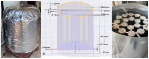
As seen in Figure 3 a, a Water-PCM storage tank (storage tank 2) of 0.5 m3 is used in the system, which has been modified for thermal enhancement in the system. It is filled with 81% of water (0.405 m3) and 17% of RT42 paraffin PCM (0.085 m3) in 18 aluminum cylinders with 0.1 m outside diameter, 0.094 m inside diameter and 0.66 m height, as shown in Figure 3 b and c, the tank contains base that occupies 0.01 m3 of tank volume (2% of tank volume). This study is focused on the Water-PCM storage tank which is located after the water storage tank and before the load.
Figure 3. Water-PCM storage tanks with (a) insulation, (b) dimensions, and (c) cylindrical PCM
The water-PCM storage tank that have twelve temperature sensors, three of them are used in the top, midpoint, and bottom of the cylindrical PCM, as seen in Figure 4, which they were measured using a DS18B20 thermometer.
Figure 4. Positions of thermocouples in PCM
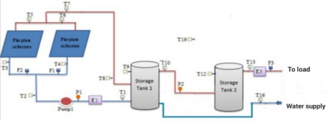
The schematic of temperature, flow meters, and pressure sensors in the closed SWHS used in this study is shown in Figure 5. The water-PCM storage tank, which is located after tank 1 and before the load, was the focus of this study and to compare energy savings with and without PCM and control the water temperature in tank 2.
Figure 5. The sensors schematic in the SWHS
2.4 RT42 PCM
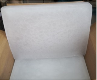
The PCM employed in this experimental study was Paraffin wax type RT42, as shown in Figure 6, which was supplied by RUBITHERM Company.
Figure 6. RT42 paraffin wax from RUBITHERM
The properties of RT42 have been indicated in Table 1.
Table 1. Properties of RT42 [29]
|
Property |
Value |
Variation with Temp |
|
Density (ρ) |
880 kg/mᵌ 760 kg/mᵌ |
15°C 80°C |
|
Latent Heat Capacity (Δh) |
165,000 J/kg |
- |
|
Tₘ |
42°C |
- |
|
Tₛ |
43°C |
- |
|
Cp |
38°C for melting 37°C for solidification |
- |
|
|
2000J/ kg K |
42°C |
The following sets of equations are used for experimental energy analysis:
3.1 Energy accumulation
Energy accumulation depend on the PCM percentage volume and PCM with latent heat capacity (Δh) significantly so, to get high energy stored need to PCM with high Δh. PCM's basic energy accumulation equation is as follow:
$Q_{\mathrm{st}}=M\left[c_{\mathrm{ps}}\left(T_{\mathrm{m}}-T_{i}\right)+x \Delta h+c_{\mathrm{p} L}\left(T f-T_{\mathrm{m}}\right)\right]$ (1)
x is the melting fraction, which can be computed using the formula below [30]:
$x=\frac{T-T_{\mathrm{s}}}{T_{\prime}-T_{\mathrm{s}}}$ (2)
where, T is the midpoint temperature of PCM, and Tₛ is the solidus temperature of PCM.
For full melting, the energy accumulation or heat absorbed (stored) (Qst) during the charging is as:
Qabs $=Q_{\mathrm{st}}=M\left[c_{\mathrm{ps}}\left(T_{\mathrm{m}}-T_{i}\right)+\Delta h+c_{\mathrm{p} L}\left(T f-T_{\mathrm{m}}\right)\right]$ (3)
3.2 Energy recovery ratio (ERR)
The ERR describes the heat recovered value as a result of the PCM discharging. The short duration of the discharging process or the lowest difference between discharge and charge times are other major factors that contribute to high ERR.
The rejected energy (Q rej) during the discharging process can be determined as in [31]:
$Q r e j=M\left[c_{\mathrm{ps}}\left(T_{i}-T_{\mathrm{m}}\right)+\Delta h+c_{\mathrm{p} L}\left(T_{\mathrm{m}}-T f\right)\right]$ (4)
The energy recovery ratio (ERR) is the ratio of PCM discharge heat to charging heat. It can be computed as [31]:
$E R R=\frac{Q r e j}{Q a b s}$ (5)
If the time (t) of both charging and discharging are taking into account then the ERR can be estimated as follow:
$E R R=\frac{\text { Qrej/time of complete discharge }}{\text { Qabs/time of complete charge }}$ (6)
3.3 System thermal capacity
Thermal capacity depends on how much quantity of energy was stored by the water and PCM so, selecting the PCM with high energy storage is necessary to obtain high thermal capacity, subsequently water kept at high temperature for long duration.
Consider a water storage tank and water–PCM storage tank, the total accumulated energy (Eₜₒₜ) with and without PCM can be found as the following respectively [32]:
$E_{\text {tot no }} p c m=\dot{\mathrm{m}}_{w} C_{p w}\left(T_{w o}-T_{w i}\right)$ (7)
where, (Eₜₒₜ,ₙₒ pcm) is the total accumulated energy without PCM.
$E_{\text {tot }} p c m=\dot{m}_{w} C_{p w}\left(T_{w a v}-T_{w i}\right)+Q_{s t}$ (8)
where, (Eₜₒₜ, pcm) is the total accumulated energy with PCM.
Thermal storage gain (Qths) is as [32]:
$Q_{t h s}=\frac{E_{tot}, \quad pcm}{E_{tot,no} \quad pcm}$ (9)
3.4 System efficiency
The following equations were employed to determine the efficiency of the system experimentally without and with PCM respectively [33]:
$\eta_{S_{,no}} \,\,\,\, pcm=\frac{E_{tot,no} \quad pcm}{I * A_{c}}$ (10)
where, (ηs,ₙₒ pcm) is the system efficiency without PCM.
$\eta_{s, p c m}=\frac{E_{tot,} \quad pcm}{I * A_{c}}$ (11)
where, (ηs,pcm) is the system efficiency with PCM.
The error is the variance between the correct value and the measured value. If a single number (U) is required to indicate a tolerable limit of error for a given factor, a model incorporating bias and precision errors should be used, where the range is X±U. If the basic parameters are (X1, X2, X3…. Xi) and the outcomes are (r), the following is the result [34]:
$r=f\left(X_{1}, X_{2}, X_{3}, \ldots, X_{i}\right)$ (12)
The Taylor series approach can be used to estimate the propagation effect [35]:
$U_{r}=\left(\frac{\partial r}{\partial x_{1}}\right)^{2} U_{X 1}^{2}+\left(\frac{\partial r}{\partial x_{2}}\right)^{2} U_{X 2}{ }^{2}+$$\left(\frac{\partial r}{\partial x_{3}}\right)^{2} U_{X 3}{ }^{2} \ldots+\left(\frac{\partial r}{\partial X_{i}}\right)^{2} U_{X i}^{2}$ (13)
Each component in Eq. (13) is divided by r2 to get the first form. The right hand side terms are then multiplied by (Xi/Xi) 2, which equals 1. As a result:
$\frac{\mathrm{U}_{\mathrm{r}}^{2}}{\mathrm{r}^{2}}=\left(\frac{\mathrm{X}_{1}}{\mathrm{r}} \frac{\partial \mathrm{r}}{\partial \mathrm{X}_{1}}\right)^{2}\left(\frac{\mathrm{U}_{\mathrm{X} 1}}{\mathrm{X}_{1}}\right)^{2}+\left(\frac{\mathrm{X}_{2}}{\mathrm{r}} \frac{\partial \mathrm{r}}{\partial \mathrm{X}_{2}}\right)^{2}\left(\frac{\mathrm{U}_{\mathrm{X} 2}}{\mathrm{X}_{2}}\right)^{2}+$$\left(\frac{\mathrm{X}_{3}}{\mathrm{r}} \frac{\partial \mathrm{r}}{\partial \mathrm{X}_{3}}\right)^{2}\left(\frac{\mathrm{U}_{\mathrm{X}_{3}}}{\mathrm{X}_{3}}\right)^{2}+\cdots+\left(\frac{\mathrm{X}_{\mathrm{i}}}{\mathrm{r}} \frac{\partial \mathrm{r}}{\partial \mathrm{X}_{\mathrm{i}}}\right)^{2}\left(\frac{\mathrm{U}_{\mathrm{Xi}}}{\mathrm{X}_{\mathrm{i}}}\right)^{2}$ (14)
where, Ur/r denotes the result's relative uncertainty, which is the product of two factors for each parameter. The relative uncertainty for each factor is represented by the factors (UXi/Xi). The average uncertainties of the main parameters are explained in the Table 2.
Table 2. The average uncertainties of the main parameters
|
Parameter |
Uncertainty (Ur) |
|
Temperature |
± 0.5°C |
|
Mass flow rate |
≤ 2% |
|
Solar radiation |
≤ 1.8% |
|
PCM mass |
±2% |
The results for system efficiency enhancement, discharging and charging processes, system efficiency enhancing, energy analysis, and carbon footprint reduction are presented in this section. Variations in water inlet temperature and mass flow rate had an impact on all of these results.
5.1 Charging time
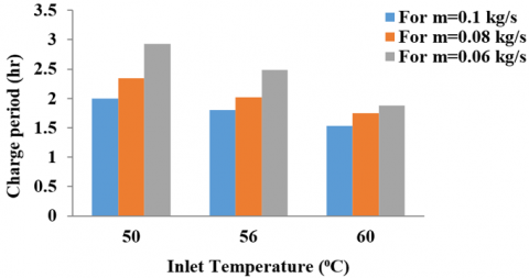
The charging periods of RT42 for the nine cases are shown in Table 3. Using 18 cylindrical Aluminum caused to high PCM surface area and this resulted in high heat transfer rates. Cylinders have low volume to surface area ratio and as a result, the heat transfer rate is quite high, correspondingly the required charging time is less. When the charging period is less, it means that the system is able to store the largest amount of energy in the least period, and this means that the system operates with higher efficiency. So the minimum charging period of RT42 was for the highest values of inlet temperature to the water-PCM tank (Tin) and water mass flow rate ($\dot{m}_{\mathrm{W}}$) i.e. 60℃ and 0.1 kg.s-¹, which the same boundary conditions that the system got on the highest efficiency. The maximum time required for charging was found for lowest Tin and $\dot{\mathrm{m}}_{\mathrm{w}}$ values i.e. 50℃ and 0.06 kg.s-¹, whereas the medium time required for charging was found at medium Tin and $\dot{\mathrm{m}}_{\mathrm{w}}$.
Table 3. Charging period in hours for each case
|
$\mathrm{T}_{\mathrm{in}} / \dot{\mathrm{m}}_{\mathrm{w}}$ |
0.06 kg/s |
0.08 kg/s |
0.1 kg/s |
|
50℃ |
2.93 |
2.35 |
2 |
|
56℃ |
2.49 |
2.02 |
1.8 |
|
60℃ |
1.88 |
1.75 |
1.53 |
The charging time taken can be seen in Figure 7. It is clear from the graph that the charging period gets shorter as Tin gets higher. In comparison, the time it takes to charge decreases as $\dot{\mathrm{m}}_{\mathrm{w}}$ increases.
Figure 7. Variation in charging period of RT42 as inlet temperature and mass flow rate change
5.2 Discharging time
The discharging periods for nine cases are shows in Table 4. The maximum time required for discharging was found for highest $T_{\text {in }}$ and lowest $\dot{\mathrm{m}}_{\mathrm{w}}$ values i.e. $33^{\circ} \mathrm{C}$ and $0.06 \mathrm{kg.s}^{-1}$, whereas the minimum discharging period was for the lowest value of $T_{\text {in }}$ and highest value $\dot{\mathrm{m}}_{\mathrm{w}}$ i.e. $24^{\circ} \mathrm{C}$ and $\mathrm{kg} / \mathrm{s}$. Also, the medium time required for discharging was found at medium $T_{\text {in }}$ and $\dot{\mathrm{m}}_{\mathrm{w}}$.
Table 4. Discharging period in hours for each case
|
$\mathrm{T}_{\mathrm{in}} / \dot{\mathrm{m}}_{\mathbf{w}}$ |
0.06 kg/s |
0.08 kg/s |
0.1 kg/s |
|
33ºC |
3.2 |
3.05 |
2.48 |
|
28ºC |
2.68 |
2.15 |
2 |
|
24ºC |
2.12 |
1.98 |
1.65 |
Figure 8. Variation in discharge period of RT42 as inlet temperature and mass flow rate change
Figure 9. Charging and discharging processes for $\dot{\mathrm{m}}_{\mathrm{w}}=0.1 \mathrm{~kg} \cdot \mathrm{s}^{-1}$ and $T_{\text {in }}$ of $60^{\circ} \mathrm{C}$ and $33^{\circ} \mathrm{C}$ for charging and discharging respectively
The discharging time taken can be seen in Figure 8. It is clear from the graph that the discharging period gets shorter as Tin gets lower. In comparison, the time it takes to discharge decreases with $\dot{\mathrm{m}}_{\mathrm{w}}$ increases, because heat is transported away faster by the colder fluid at higher $\dot{\mathrm{m}}_{\mathrm{w}}$.
Figure 9 represents an example of the charging and discharging processes with PCM initial and final temperatures for charging of 18°C, 56°C respectively, PCM initial and final temperatures for discharging of 56°C, 18°C respectively, $\dot{\mathrm{m}}_{\mathrm{w}}$=0.1 kg.s-¹ and Tin of 60°C and 33°C for charging and discharging respectively.
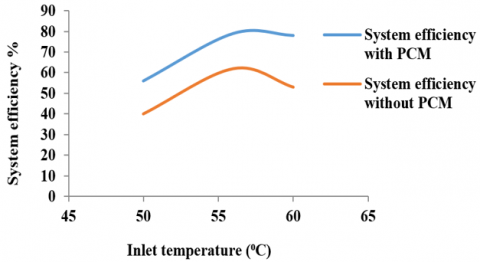
5.3 Efficiency enhancing
One of the most important benefits of integrating PCMs with SWHS is increased system efficiency. Figure 10 depicts a comparison of system efficiency with and without PCM. The results show that the energy stored by the PCM increased the system efficiency for the same boundary conditions in all cases by 12–25%, achieving thermal performance.
Figure 10. Comparison between the system efficiency with and without PCM
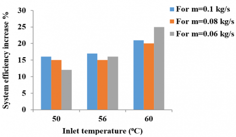
Figure 11 depicts the increase in system efficiency achieved using PCM for the nine cases. The graph clearly shows that the system efficiency was increased significantly by 25% for highest Tin and lowest $\dot{\mathrm{m}}_{\mathrm{w}}$ values i.e., 60ºC and 0.06 kg.s-¹, whereas the minimum increase in system efficiency was 12%, that was found for the lowest values of Tin and $\dot{\mathrm{m}}_{\mathrm{W}}$ i.e., 50ºC and 0.06 kg.s-¹. It was also discovered that as Tin increases the system efficiency, whereas as $\dot{\mathrm{m}}_{\mathrm{w}}$ increases at constant Tin, system efficiency may increase or decrease due to energy storage in the storage tank 2.
Figure 11. System efficiency increase for the nine cases by using PCM
5.4 Energy analysis
5.4.1 Energy saving
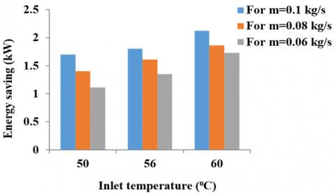
PCMs can store a significant amount of energy during phase change material. Heat energy is stored in PCM and released when the material cools and goes through the phase change process. For the same PCM mass, $\mathrm{C}_{\mathrm{p}}, \Delta \mathrm{h}$ and melting fraction, the energy-saving in PCM depends on the initial and final temperatures of the PCM for the charging process. The higher energy stored in PCM is obtained with a lower PCM initial temperature and the highest final temperature of the PCM. The results for accumulated energy by RT42 in kWh obtained for all nine cases are shown in Figure 12.
The maximum energy stored by RT $42(2.12 \mathrm{~kW})$ was found for highest values of $T_{\text {in }}$ and $\dot{\mathrm{m}}_{\mathrm{w}}$ i.e. $60^{\circ} \mathrm{C}$ and $0.1 \mathrm{~kg} \cdot \mathrm{s}^{-1}$, whereas the minimum energy stored $(1.11 \mathrm{~kW})$ was for the lowest values of $T_{\text {in }}$ and $\dot{\mathrm{m}}_{\mathrm{w}}$ i.e. $50^{\circ} \mathrm{C}$ and $0.06 \mathrm{~kg} . \mathrm{s}^{1}$.
Figure 12. Energy saving for RT42 for different Tin and $\dot{\mathrm{m}}_{\mathrm{w}}$
Figure 13 depicts the results obtained for the total accumulated energy by the system in kWh at various times of the year. In comparison, it is clear from the graph that for the same boundary condition, the system energy savings with PCM are larger than those without PCM on all days. This is due to energy savings as sensible energy in the water-PCM storage tank. The results show that the maximum system energy stored with PCM was 10.9 kW on December 15, while the minimum system energy stored with PCM was 7.1 kW on November 29; this is primarily due to differences in solar radiation for different days and, to a lesser extent, depends on the boundary conditions.
Figure 13. The total system energy saving with and without paraffin wax RT42 for different days for November and December, 2021
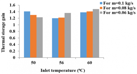
5.4.2 Thermal storage gain
Thermal storage gain (Qths), which is the proportional of the total energy stored with PCM to that without PCM, is another important energy analysis for using PCM in SWHS.
The higher thermal storage gain means that the RT42 caused to more thermal enhancement of the SWHS, as shown in Figure 14. Therefore, the highest increase in system efficiency and the maximum Qths was obtained with the same boundary conditions, at the highest inlet temperature and lowest mass flowrate values 60ºC and 0.06 kg.s-¹ respectively. The maximum Qths was 1.48 whereas; the minimum Qths was 1.2 which obtained at 56ºC and a rate of 0.1 kg.s-¹.
Figure 14. Variation in Qths as inlet temperature and mass flow rate change
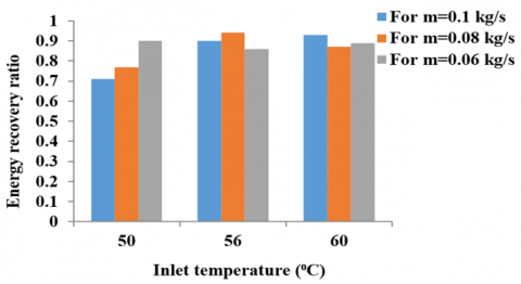
5.4.3 Energy recovery ratio
The energy recovery ratio (ERR) results for all nine scenarios are shown in Figure 15. The graph clearly shows that RT42 has a high ERR because it lacks hysteresis. In practice, it is difficult to precisely control the details of any phase change material, including hysteresis and sub-cooling errors.
Figure 15. Variation in ERR as inlet temperature and mass flow rate change
5.4.4 Electricity consumption reduction
The energy saving in kWh can be estimated by multiply the energy saving in kW to the discharge time in hours. Figure 16 illustrates that the maximum amount of energy stored is 4.75 kWh, which was obtained at lowest Tin and highest $\dot{\mathrm{m}}_{\mathrm{w}}$ values of 50ºC and 0.1 kg.s-¹ respectively, whereas the minimum energy stored is 3.2 kWh, which was obtained at highest Tin and $\dot{\mathrm{m}}_{\mathrm{w}}$ values of 60ºC and 0.1 kg.s-¹ respectively.
Figure 16. Variation in energy saving by RT42 as inlet temperature and mass flow rate change
Figure 17 illustrates that the maximum amount of energy stored by the system was 30.2 kWh on 21th November, whereas the minimum energy stored was 8.8 kWh on 12th December. The average daily energy stored by the system is 19.3 kWh.
Figure 17. Energy saving in kWh by the system at various days of the year
5.5 Carbon footprint reduction
Due to PCM, electric heaters that operate for shorter periods of time will save money while also lowering their CO2 emissions.
The kerosene amount employed in a liter to produce heat in kJ is calculated as follows [36]:
One litter of kerosene equals 37,600 kJ of heat. The amount of CO2 released by the heat produced by electric heaters is then calculated in kWh: 0.37 kilograms of CO2 equals 1 kWh of heat. As a result, for every 3.76 kWh of energy stored by RT42, the average daily carbon footprint reduction by RT42 is 1.4 kg CO2. Furthermore, if the system stores 19.3 kWh per day, the system's daily and annual carbon footprint reductions are 27 kg CO2 and 7044 kg CO2 respectively.
A practical effort to improve the performance of a water-PCM storage system combined with a SWHS, as a water-PCM storage tank developed and built under the climate conditions of Erbil city in Kurdistan Region-Iraq. The following are the main conclusions from this work:
(1) The employ of PCM in TES storage has proven to be an effective way to reduce fossil energy usage and increase reliance on SE.
(2) Excess heat can be kept in a PCM as latent heat during the day and used to keep water warm and acceptable for use in all domestic applications at night.
(3) The integrating of FPSWHS with RT42 is suitable for application in Erbil city, it concluded from experimental study that the best energy saving with minimum discharge and charge time obtained at 60℃ inlet temperature with 0.1 kg/s mass flow rate. Furthermore, the system efficiency was improved by 25%.
(4) It concluded from the other studies which that mentioned in this study that the PCM in cylindrical modules performs significantly better than the PCM in other form modules. Furthermore, the cylindrical module is more practical in terms of installation and production.
Future research could focus on a more in-depth investigation with different PCMs. SWHS cost estimates should be thoroughly examined in order to determine potential savings and implementation costs.
This work has been supported by the Center of Research at Erbil Polytechnic University in Erbil-Iraq.
|
Ac |
Collector Surface Area [m2] |
|
Cₚ |
Specific heat, J. kg-1. K-1 |
|
I |
Total radiation on horizontal surface [W.m-2] |
|
k |
Thermal conductivity, W.m-1. K-1 |
|
M |
Phase change material mass [kg] |
|
$\dot{\mathrm{m}}$ |
Mass flow rate [kg.s-¹] |
|
Q |
Sensible heat stored [W] |
|
Qₛₜ |
Thermal energy stored [W] |
|
Qths |
Thermal storage gain |
|
Qu |
Useful heat energy gain [W] |
|
r |
Resulted value |
|
T |
Phase change material temperature in phase change state [ºC] |
|
Tf |
Final temperature of Phase change material [ºC] |
|
Ti |
Initial temperature of Phase change material [ºC] |
|
Tin |
Water-PCM tank inlet temperature [ºC] |
|
T⸤ |
Liquid temperature of Phase change material [ºC] |
|
Tₘ |
Melting temperature [ºC] |
|
Twav |
Average temperature of water-PCM storage tank [ºC] |
|
Twi |
Water tank inlet temperature [ºC] |
|
Two |
Water tank outlet temperature [ºC] |
|
Ur |
Uncertainly of calculated parameter |
|
Ux |
Uncertainty of measured variable |
|
X |
Melting fraction |
|
Greek symbols |
|
|
ρ |
Density [kg.m-3] |
|
Δh |
Latent Heat Capacity [J] |
|
η |
Efficiency |
|
Subscripts |
|
|
abs |
Absorbed |
|
c |
Collector |
|
f |
Final |
|
i |
Initial |
|
in |
Inlet |
|
l |
Liquid |
|
m |
melting |
|
rej |
Rejected |
|
s |
Solid |
|
s,nopcm |
System without phase change material |
|
s, pcm |
System with phase change material |
|
st |
Stored |
|
tot |
Total |
|
ths |
Thermal storage |
|
w |
Water |
|
Abbreviations |
|
|
CFD |
Computing Fluid Dynamics |
|
ES |
Energy storage |
|
ERR |
Energy recovery ratio |
|
FPC |
Flat plate collector |
|
FPSC |
Flat plate solar collector |
|
FPSWHS |
Flat plate solar water heating system |
|
LHS |
Latent Heat Storage |
|
PCM |
Phase change material |
|
SE |
Solar energy |
|
TES |
Thermal energy storage |
|
t |
Ton |
[1] Bazri, S., Badruddin, I.A., Naghavi, M.S., Seng, O.K., Wongwises, S. (2019). An analytical and comparative study of the charging and discharging processes in a latent heat thermal storage tank for solar water heater system. Solar Energy, 185: 424-438. https://doi.org/10.1016/j.solener.2019.04.046
[2] Perea-Moreno, A.J., García-Cruz, A., Novas, N., Manzano-Agugliaro, F. (2017). Rooftop analysis for solar flat plate collector assessment to achieving sustainability energy. Journal of Cleaner Production, 148: 545-554. https://doi.org/10.1016/j.jclepro.2017.02.019
[3] Fleischer, A.S. (2015). Thermal energy storage using phase change materials: Fundamentals and applications. Springer.
[4] Carmona, M., Palacio, M. (2019). Thermal modelling of a flat plate solar collector with latent heat storage validated with experimental data in outdoor conditions. Solar Energy, 177: 620-633. https://doi.org/10.1016/j.solener.2018.11.056
[5] Prasad, J.S., Muthukumar, P., Desai, F., Basu, D.N., Rahman, M.M. (2019). A critical review of high-temperature reversible thermochemical energy storage systems. Applied Energy, 254: 113733. https://doi.org/10.1016/j.apenergy.2019.113733
[6] Pandey, A.K., Hossain, M.S., Tyagi, V.V., Abd Rahim, N., Jeyraj, A., Selvaraj, L., Sari, A. (2018). Novel approaches and recent developments on potential applications of phase change materials in solar energy. Renewable and Sustainable Energy Reviews, 82: 281-323. https://doi.org/10.1016/j.rser.2017.09.043
[7] Du, K., Calautit, J., Wang, Z., Wu, Y., Liu, H. (2018). A review of the applications of phase change materials in cooling, heating and power generation in different temperature ranges. Applied Energy, 220: 242-273. https://doi.org/10.1016/j.apenergy.2018.03.005
[8] Markarian, E., Fazelpour, F. (2019). Multi-objective optimization of energy performance of a building considering different configurations and types of PCM. Solar Energy, 191: 481-496. https://doi.org/10.1016/j.solener.2019.09.003
[9] Douvi, E., Pagkalos, C., Dogkas, G., Koukou, M.K., Stathopoulos, V.N., Caouris, Y., Vrachopoulos, M.G. (2021). Phase change materials in solar domestic hot water systems: A review. International Journal of Thermofluids, 10: 100075. https://doi.org/10.1016/j.ijft.2021.100075
[10] Lamé, G., Clapeyron, B.P. (1831). Mémoire sur la solidification par refroidissement d’un globe liquide. In Annales Chimie Physique, 47(1831): 250-256.
[11] Krishnan, S., Garimella, S.V. (2004). Thermal management of transient power spikes in electronics—Phase change energy storage or copper heat sinks? Journal of Electron. Packag., 126(3): 308-316. https://doi.org/10.1115/1.1772411
[12] Pal, D., Joshi, Y.K. (2001). Melting in a side heated tall enclosure by a uniformly dissipating heat source. International Journal of Heat and Mass Transfer, 44(2): 375-387. https://doi.org/10.1016/S0017-9310(00)00116-2
[13] Nayak, K.C., Saha, S.K., Srinivasan, K., Dutta, P. (2006). A numerical model for heat sinks with phase change materials and thermal conductivity enhancers. International Journal of Heat and Mass Transfer, 49(11-12): 1833-1844. https://doi.org/10.1016/j.ijheatmasstransfer.2005.10.039
[14] Mesalhy, O., Lafdi, K., Elgafy, A., Bowman, K. (2005). Numerical study for enhancing the thermal conductivity of phase change material (PCM) storage using high thermal conductivity porous matrix. Energy Conversion and Management, 46(6): 847-867. https://doi.org/10.1016/j.enconman.2004.06.010
[15] Ghoneim, A.A. (1989). Comparison of theoretical models of phase-change and sensible heat storage for air and water-based solar heating systems. Solar Energy, 42(3): 209-220. https://doi.org/10.1016/0038-092X(89)90013-3
[16] Vikram, D., Kaushik, S., Prashanth, V., Nallusamy, N. (2006). An improvement in the solar water heating systems by thermal storage using phase change materials. In International Solar Energy Conference, 47454: 409-416. https://doi.org/10.1115/ISEC2006-99090
[17] Sharma, A., Tyagi, V.V., Chen, C.R., Buddhi, D. (2009). Review on thermal energy storage with phase change materials and applications. Renewable and Sustainable Energy Reviews, 13(2): 318-345. https://doi.org/10.1016/j.rser.2007.10.005
[18] Saw, C.L., Al-Kayiem, H. (2011). An investigation of integrated flat plate solar collector: Experimental measurement. In 2011 National Postgraduate Conference, Perak, Malaysia, pp. 1-6. https://doi.org/10.1109/NatPC.2011.6136414
[19] Longeon, M., Soupart, A., Fourmigué, J.F., Bruch, A., Marty, P. (2013). Experimental and numerical study of annular PCM storage in the presence of natural convection. Applied Energy, 112: 175-184. https://doi.org/10.1016/j.apenergy.2013.06.007
[20] Kanimozhi, B., Prabhu, A., Anish, M., Kumar, P.H. (2014). Review on heat transfer enhancement techniques in thermal energy storage systems. Int. J. Eng. Res. Appl, 4(2): 144-149.
[21] Koua, K.B., Koffi, E.P.M., Gbaha, P. (2018). Thermal performance amelioration of flat plate solar collector of an indirect dryer. Mathematical Modelling of Engineering Problems, 5: 341-347.
[22] Bamoshmoosh, A., Valenti, G. (2021). Constant-volume vapor-liquid equilibrium for thermal energy storage: Proposal of a new storage system for concentrated solar power plants. In the 6th AIGE/IIETA International Conference and 15th AIGE 2021 Conference, pp. 271-278.
[23] Abdulmunem, A.R., Abed, A.H., Hussien, H.A., Samin, P.M., Rahman, H.A. (2019). Improving the performance of solar air heater using high thermal storage materials. In Annales de Chimie-Science des Matériauxm, pp. 389-394.
[24] Zhou, Y., Jiang, Y., Liu, F., Li, Q. (2016). Thermal conductivity and thermal mechanism of aluminum nanoparticles/octadecane composite phase change materials from molecular dynamics simulations and experimental study. J. Ovonic Res, 12: 49-58.
[25] Pagkalos, C., Dogkas, G., Koukou, M.K., Konstantaras, J., Lymperis, K., Vrachopoulos, M.G. (2020). Evaluation of water and paraffin PCM as storage media for use in thermal energy storage applications: A numerical approach. International Journal of Thermofluids, 1-2: 100006. https://doi.org/10.1016/j.ijft.2019.100006
[26] Ochman, A., Chen, W. Q., Błasiak, P., Pomorski, M., Pietrowicz, S. (2021). The use of capsuled paraffin wax in low-temperature thermal energy storage applications: An experimental and numerical investigation. Energies, 14(3): 538. https://doi.org/10.3390/en14030538
[27] Chopra, K., Tyagi, V.V., Pandey, A.K., Popli, S., Singh, G., Sharma, R., Sari, A. (2022). Effect of simultaneous & consecutive melting/solidification of phase change material on domestic solar water heating system. Renewable Energy, 188: 329-348. https://doi.org/10.1016/j.renene.2022.01.059
[28] Tompkins, E.L., Vincent, K., Nicholls, R.J., Suckall, N. (2018). Documenting the state of adaptation for the global stocktake of the Paris Agreement. Wiley Interdisciplinary Reviews: Climate Change, 9(5): e545.
[29] Charvát, P., Klimeš, L., Ostrý, M. (2014). Numerical and experimental investigation of a PCM-based thermal storage unit for solar air systems. Energy and Buildings, 68: 488-497. https://doi.org/10.1016/j.enbuild.2013.10.011
[30] Bilir, L., Ilken, Z. (2005). Total solidification time of a liquid phase change material enclosed in cylindrical/spherical containers. Applied Thermal Engineering, 25(10): 1488-1502. https://doi.org/10.1016/j.applthermaleng.2004.10.005
[31] Sokar, M.S., MAnsour, S.A., Ali, A.A.A., Elnekiety, M.H. (2020). Investigation of paraffin wax with ZnO nanorods for performance enhancement of solar thermal energy storage. (Dept. M). MEJ. Mansoura Engineering Journal, 45(3): 19-28. https://doi.org/10.21608/bfemu.2020.111571
[32] Sarafraz, P. (2014). Thermal optimization of flat plate PCM capsules in natural convection solar water heating systems.
[33] Saleh, A.M., Mueller Jr, D.W., Abu-Mulaweh, H.I. (2015). Flat-plate solar collector in transient operation: modeling and measurements. Journal of Thermal Science and Engineering Applications, 7(1): 014502. https://doi.org/10.1115/1.4028569
[34] ASME, Test Uncertainity ASME PTC 19.1-2005. New York: The american society of mechanical engineers, 2006.
[35] Coleman, H.W., Steele, W.G. (2009). Experimentation, Validation, and Uncertainty Analysis for Engineers, third edit. New Jersey: John Wiley & Sons, INC.
[36] Demirel, Y. (2012). Energy: Production, conversion, storage, conservation, and coupling. Springer Science & Business Media.