Mais Alzgool![]()
© 2024 The author. This article is published by IIETA and is licensed under the CC BY 4.0 license (http://creativecommons.org/licenses/by/4.0/).
OPEN ACCESS
The efficiency of solar panels is highly affected by the ambient temperature, which limits electrical energy production. There are several cooling techniques to minimize the PV panels’ temperature. Using a Phase Change Material (PCM) is one of the critical techniques to choose. The desirable thermal, kinetic, and chemical properties of PCM are critical conditions for the steady-state thermal Latent Heat Storage Unit efficiency (LHSU). The Phase change material must be thermally stable and dependable. Due to the hot season temperatures in Jordan; RT35 has been chosen as a PCM. The poor thermal conductivity of this material is one of its drawbacks, thus, aluminum fins as a high conductivity material have been added to the proposed design in order to manage the temperature of the phase change material as a Thermal Conductivity Enhancer (TCE). This study intends to enhance the PV cells’ performance by proposing a new design of PV panels with RT35 and fins as a cooling technique. As a result, adding RT35 has a significant impact on reducing the PV panel’s temperature by 16℃, while adding the rectangular fins contributes to decreasing the temperature by another 2℃. Thus, adding RT35 in conjunction with fins will enhance the efficiency and the output power of the PV panel resulting in an 11% increase in electrical production. The results have been validated through ANSYS simulation as well as experimental work which shows a good correlation with the theoretical analysis.
PV cooling, phase change material, RT35, thermal conductivity enhancer, PV thermal module
Temperature exerts an enormous effect on PV modules' capability to produce power. PV cell performance declines with temperature, mostly as a result of elevated internal carrier recombination rates induced by higher carrier concentrations. Operating temperature has a significant role in the solar energy conversion process. Due to the phenomenon of thermal expansion, greater temperatures contribute to the degradation or breakdown of a solar module, leading to its deterioration or failure.
Conventional silicon-based solar cells typically have an efficiency of only 15-20% in converting incoming light into electricity. The remaining energy is therefore converted into heat, which raises the temperature of the photovoltaic module [1]. Temperature is an essential aspect to consider because it is widely recognized that elevated operating temperatures reduce the effectiveness of solar cells.
Minimizing the operating temperature of the PV module is crucial in order to optimize efficiency. Ideally, the temperature should be maintained at the level of Standard Test Conditions (STC) or 25°C PV cell temperature with 1000 W/m2 irradiation. Improving the efficiency of PV modules can be greatly enhanced by effectively regulating their temperature.
Research has shown that the temperature of PV cells can be reduced by approximately 18°C when exposed to high levels of irradiation. This drop in temperature leads to an increase in electrical production of between 9% and 12% [2, 3]. The power losses triggered by the rise in the temperature of the cells range from 0.39% per degree Celsius at standard test conditions to 0.64% per degree Celsius, along with an increase in module aging [4].
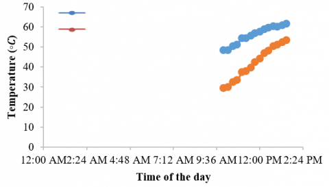
Multiple researchers have suggested different cooling methods utilizing air (either through natural or forced circulation), water (via a water-cooling system or heat pipes), thermoelectric devices, or Phase Change Materials (PCM) to mitigate the rise in temperature of PV modules. Several of these devices are passive, but others are active [5]. In addition, numerous researchers assess the effectiveness of a cooling system utilizing Phase Change Material (PCM) for both glazed and unglazed Photovoltaic (PV) panels. The phase change material (PCM) absorbs surplus heat from the panels, hence decreasing their temperature [6-10]. Photovoltaic (PV) and solar thermal (PV/T) modules can be interconnected to provide simultaneous generation of electricity and heat within a single module [11-13]. Due to its high heat of fusion, PCM has the ability to absorb a significant amount of energy without changing its state from solid to liquid or vice versa. Additionally, the temperature remains constant during this phase shift. Therefore, PCM might be considered a preferable option for cooling applications [14-16]. When phase change material (PCM) is paired with a photovoltaic (PV) module, the temperature of the module remains constant during the transition phase because the PCM absorbs heat. A multitude of studies explore various system configurations and diverse phase change materials (PCMs) such as RT42, RT31, and RT25. Only a limited number of research have been undertaken in recent years to investigate the effects of using the RT35 as a phase change material (PCM) with different heat sink configurations [17-20]. Heat sinks incorporating phase change materials (PCM) enhance the thermal conductivity of the material [8]. Shan et al. [9] examines the consequences of using a phase change material called RT35 (Rubitherm) on the operating temperature of PV panels. The study shows that RT35 can effectively lower the temperature of the panels and keep it in close proximity to the surrounding temperature. When the RT35 layer is combined with the module, the module's temperature decreases by around 25 degrees while being exposed to a constant radiation of 750 W/m2 [21]. Nevertheless, a real-time experiment was conducted to verify the experimental findings based on the Malaysian weather, and the results are presented in Figure 1 [22].
Figure 1. The effect of PCM on the PV modules’ temperature [22]
As the blue line represents the temperature without PCM while the yellow line shows the temperature with PCM in Figure 1. Without incorporating phase change material, the temperature of the PV module increases to 52°C. However, when a 0.02 m wide layer of PCM (RT35) is used with the PV module, the temperature rise is limited to 41°C. Where the temperature of the PV module declined by 11 degrees Celsius and maintained a constant level for a duration of 5 hours, as depicted in Figure 1 (between 11.00 AM and 4.00 PM) [22].
A parametric study was conducted to examine the thermal efficiency of an aluminium heated plate that mimics a PV solar cell. This study involved testing various heat sink topologies, applying varied levels of heat flux, and utilizing different combinations of phase change materials (PCM) and PCM nanoparticles with varying amounts of nanoparticles [23-27]. Heat sinks equipped with hollow cylindrical fins are effective in mitigating the issue of the phase change material (PCM) combining with nanoparticles that have a lower thermal conductivity.
The front surface temperature is reduced from 2.0℃ to 5.5℃ with an enhancement of 2.5 to 11.25 percent for the configuration of mixing Al2O3 nanoparticles with RT35HC and gradually increasing the volume fraction of the nanoparticles from 0.12 percent to 0.78 percent by its volume. Employing the RT35HC PCM at a heat flux of 850 W/m2 will prolong the lifespan of the solar cell. At greater heat fluxes, the RT35HC PCM with heat sinks and Al2O3 nanoparticles will be a good option, with a drop in the front surface temperature of (35.9–51.3)% [13].
Three PCMs were selected based on the average ambient temperature of the studied case [23]. The study examined the impact of selected phase change materials on many factors including container size, insulation, temperature of PV cells, conversion efficiency, power production, and the melting temperature of these materials. The results indicate that inadequate container heights led to a greater temperature rise in the PV/PCM module compared to the typical system during daylight hours. The optimal height for tank RT31 is 110 mm without insulation, and it increases to 120 mm when insulation is provided. The heights measured using RT25 were 120 and 125mm [2].
Therefore, this study examined the utilization of phase change materials (RT35) for passive cooling of PV systems, taking into account the average ambient temperature of the specific area. RT35, when equipped with thermal basins, shows potential as an effective option for managing high heat flows by reducing the temperature of the front surface. When the phase change material (PCM) is completely melted, the temperature of the photovoltaic (PV) cells in the proposed PV-PCM/fins system may be higher than that observed in a typical PV system. PCM can function as a thermal resistance, leading to heat dissipation at the rear of the PV panel and thus increasing the temperature of the PV panel. In winter, when the temperature of the PCM drops below its melting point, this behaviour may also occur. The heat transfer rate in the PCM is raised as a result of reducing the size of the PCM and increasing the amount of fins material in the system. The fins will reduce the necessary time for regulating the temperature of the PV module. Conversely, the inclusion of fins will result in an augmented weight of the PV panel.
Consequently, there are multiple cooling methods available to reduce the temperature of PV panels as mentioned before, however only a few research have examined the use of RT35 for this purpose. Furthermore, these experiments investigated the impact of RT35 on improving the performance of PV panels under constant solar radiation. In this study, the RT35 has been selected as the regulator to control the temperature of the PV panel throughout the day, taking into account varying solar irradiation levels. The choice of RT35 as a phase change material (PCM) was determined by the mean temperature experienced in Jordan during the summer season. Hence, this study provides a comprehensive analysis proposing a design utilizing RT35/fins to significantly improve the heat transfer rate and cooling performance of the PV panel. This is achieved by selecting a smaller RT35 size and incorporating aluminium fins.
With the aid of historical weather information, the methodology of the presented study consists of ANSYS simulation with the aid of experimental assessment of the proposed PV-RT35/fins performance for PV cooling in the hot climate of Zarqa, Jordan. Zarqa is considered Jordan's industrial center. Where more than half of Jordan's factories are based there, in addition, Zarqa experiences hot, dry summers and cool winters due to its semi-arid environment and this will have an impact on how well the PV projects function in this city. Consequently, a PV-RT35/fins design has been proposed to enhance the PV panel's performance in this location. Using the estimated short-circuit current and open-circuit voltage of the respective PV panels, and hence the electrical power is determined.
3.1 PV panels performance based on Rubitherm (RT35)
Rubitherm (RT35), a phase change material with good efficiency, has been selected based on the average ambient temperatures in Jordan. The melting point of the selected material is (5-6) degrees higher than the average temperatures in the summer of Jordan. The experiment selected RT35 (34-36°C) as a cooling material for investigation. RT35 is a commercially available paraffin PCM manufactured by Rubitherm GmbH in Germany [28].
To study the performance of the PV panel’s temperature the study of the ambient temperature of the selected location is required. As shown in Figure 2, the climate of Zarqa is hot in the summer and cold in winter. The warmest month is August however, the coldest in January as shown in the dotted lines. Most precipitation is seen in January and usually does not exceed 25mm.
Figure 2. Ambient temperatures in Jordan based on the selected location (Zarqa, Jordan) [29]
3.1.1 RT35 properties
Rubitherm (RT35) is a type of pure phase change material (PCM) that stores and releases significant amounts of thermal energy at a practically constant temperature by undergoing the process of phase change between solid and liquid states (melting and congealing). To design RT35 with the PV panel, it is necessary to consider the major features of this material, which are stated in Table 1.
Table 1. RT35 properties [28]
|
RT35 Property |
Typical Values |
|
Melting temperature |
(29-36)℃ Main peak 33℃ |
|
Congealing temperature |
(36-31)℃ Main peak 35℃ |
|
Heat storage capacity ±7.5% |
160 kJ/kg |
|
Specific heat capacity |
2 kJ/kgK |
|
Density (solid) at 15℃ |
0.86kg/I |
|
Density (liquid) at 45℃ |
0.77kg/I |
|
Heat conductivity for both phases |
0.2 W/mK |
|
Volume expansion percentage |
12.5% |
|
Flash point temperature |
167℃ |
|
Maximum operating temperature |
65℃ |
3.1.2 RT35 thickness selection
PCM thickness is a crucial component in the PV-PCM system [30, 31]. The current study examines the impact of phase change material (PCM) thickness on the performance of photovoltaic (PV) panels [31, 32]. The research findings indicate that an increase in the thickness of the PCM leads to a greater decrease in the PV temperature. Therefore, it is necessary to determine the optimal thickness of RT35 for optimal performance. Research has shown that for RT35, an increase in thickness of 4.9mm results in an average increase in melting time of around 11 minutes [3]. Furthermore, the photovoltaic (PV) temperature of a PV-PCM system may exceed that of a standard PV module once the phase change material (PCM) is completely liquefied. The physical state of PCM will change from solid to liquid along with the absorption of heat. The temperature of the PCM remains constant at the melting point, therefore it can regulate its temperature. Therefore, it is crucial to choose the suitable thickness of PCM based on the ambient temperature throughout summer and winter, considering that the temperatures of PCM will be lower than its melting points. It emphasizes the importance of choosing the correct PCM thicknesses and melting points according to the climatic conditions of the chosen location. This work [29] has examined and taken into account the actual climatic conditions of Zarqa city. Ultimately, the determination of the RT35 thickness will be based on the qualities of RT35, the climate conditions of the city, and the design of the aluminum fins. Figure 3 depicts the proposed layout of the PV panel based on RT35 where a 2.5 cm thick RT35 has been added with the main components of the solar panel.
Figure 3. RT35-PCM thickness within the proposed PV panel
3.1.3 RT35 with fins
Using heating components in conjunction with phase change materials (PCM) offers the advantage of decreasing the thermal conductivity of the material. Different designs of phase change materials (PCMs) can boost the rate at which heat is transferred to the PCM. The use of heat sinks with the RT35 PCM improves performance by 20.2% to 46% compared to the free surface design [8]. An analysis has been conducted to determine the mean temperatures on the frontal surface of the system using different fin configurations. The fins are capable of efficiently controlling the increase in temperature on the front surface of the PV/PCM system. Put simply, fins regulate the temperature of the system’s front surface by minimizing thermal stratification. In addition, fins decrease the time required to adjust the surface temperature, although the added weight from the metal fins may pose a concern [30-33]. This study examines several fin shapes and dimensions to determine the optimal design for efficiently controlling temperature increase while minimizing the volume of phase change material (PCM) and aluminum. Consequently, the thickness of the RT35 used is determined to be 2.5cm. The dimensions of the fins design are set to maintain a distance between the aluminum plates ranging from 4cm to 5cm. This is done to ensure a consistent temperature profile within the PCM and prevent the formation of pores and voids. The fins have a thickness of 2mm and a height of 1.5cm. The distance between the edges of the fins is 5cm. The design structure has been incorporated into the traditional PV panel, and the aluminum fins have been filled with the RT35 mixture. Figure 4 depicts the PV-RT35/fins design that will be evaluated for its performance in this study.
Figure 4. The proposed PV-RT35/fins design
In this section, the mathematical modelling, simulation and experimental validation of the proposed design will be presented and discussed.
4.1 Mathematical modelling
4.1.1 PV panel with RT35 mass determination
Liquefied RT35 density is 770 kg/m2 and its solid density is 860 kg/m2 [28]. Substituting these values in Eqs. (5) and (6) will obtain the volume of the used RT35 as thevolume of the PV panel and the fins volume also are required.
Initially the fins volume using Eq. (1) could be found as follows:
Volume Fins=(lengthPV *widthPV *thicknessPV)+((number of fins*thicknessFins)*widthFins *heightFins) (1)
The dimensions of the selected PV panel could be found from its data sheet [34], so the volume of fins will be:
Volume Fins=(1.2*0.54*0.002)+((25*0.002)*0.52*0.015)=1.686*10−3m3 (2)
Then the RT35 volume could be determined as follows:
Volume RT35= Volume PV Panel − Volume Fins (3)
Volume RT35=(1.2∗0.54∗0.025)−1.686∗10−3=0.0145 m3 (4)
After that RT35 mass in liquid and solid states could be found as follows:
massRT35−liquid=volume RT35−liquid*density RT35−liquid (5)
=0.0145*770=11.16kg
massRT35−solid=volume RT35−solid *density RT35−solid (6)
=0.0145*860=12.47kg
massFins=volume Fins*density Fins (7)
=1.686*10-3*2700=4.55kg
The total mass of the proposed PV-RT35/fins design is:
Total mass = mass RT35+ mass Fins + mass PV Panel (8)
Total mass=12.47+4.55+6.5=23.5kg
In conclusion, the total mass of the proposed PV-RT35/fins will be 23.5kg.
4.1.2 PV cell with RT35 operating temperature determination
The calculation of cell temperature is based on the idea of Normal Operating Cell Temperature (NOCT), as provided by photovoltaic module manufacturers and specified by the Eq. (9):
Tcell =Ta+(NOCT−20)(GB800) (9)
The definition of NOCT is based on specific conditions: a wind speed of 1 m/s, an ambient temperature of 20˚C, and solar irradiance measured in watts per square meter GB (W/m2). Ta represents the ambient temperature in degrees Celsius. To ascertain the progression of the hourly air temperature Ta. The thermophysical correlation between the PV module and phase change material can be depicted using the reference system illustrated in Figure 5.
Figure 5. Thermodynamic reference model of PV-PCM system [24]
According to the reference system the energy balancing equation of the PV-PCM system could be represented by Eq. (10) as follows:
cpvdTpvdt=[Effective Irradiance (Ireff)−Radiation (QR)−Power(PE)−Convection (Qcv)−heat Stored by PCM plate (QH)] (10)
The rate of temperature variation times to the heat capacity (Qcv) of the PV module is equal to the difference between input and output energy. The value of ((dT PV)/DT) must be determined from the preceding equation to determine the temperature of the PV-RT35 system with regard to time. The components of the right sides of the line solution, which may be found in the following formula, should be calculated. The following formula can be used to determine effective irradiance [30]:
Ireff =∅∗α (11)
The absorption constant of panel (mono) α=1.
The radiated energy may be computed using the Stefan-Boltzmann equation, which states that temperature and radiation have the following relationship:
QR=εp⋅σ(T2pv+T2s)(Tpv+Ts) (12)
where, Boltzmann constant σ=5.67×10⁻⁸W/m2.k4 and the emissivity of the module Ep=0.91, Ts is the sky temperature which could be calculated by modified Swinbank equation as follows:
Ts=0.037536 T1.5amb+0.32 Tamb (13)
As the electrical power PE depends on the insolation and temperature of the module then it could be calculated using the following Eq. (14):
Power (PE)=CFF⋅{∅ln(K1∅)Tpv} (14)
While the convection heat loss (Qcv) is the term used to describe the heat loss induced by convection and could be calculated as follows:
QcV=(hfront,natural +hfront,forced +hrear )∗( TPV−Tamb) (15)
where, hfront,_natural, hfront,forced and hrearare the heat loss coefficients which could be determined mathematically.
In order to find out the PV cell temperature based on PCM (RT35) the temperature distribution of the predefined location Zarqa, Jordan is required [33-35]. Using the Photovoltaic Geographical Information System (PVGIS) the ambient temperature distribution of the city has been found and listed in Table 2.
Thus, the calculated results have been summarized in Table 3.
Table 2. The irradiation and ambient temperature distribution during the day in zarqa city [29]
|
Time |
G(w/m2) |
TCell (℃) |
Tamb(℃) |
|
4:45 AM |
251 |
23.85375 |
16.01 |
|
5:45 AM |
647 |
39.12875 |
18.91 |
|
6:45 AM |
1081 |
55.45125 |
21.67 |
|
7:45 AM |
1444 |
69.085 |
23.96 |
|
8:45 AM |
1726 |
79.6075 |
25.67 |
|
9:45 AM |
1851 |
84.89375 |
27.05 |
|
10:45 AM |
1831 |
85.31875 |
28.1 |
|
11:45 AM |
1671 |
80.98875 |
28.77 |
|
12:45 PM |
1388 |
72.445 |
29.07 |
|
1:45 PM |
998 |
60.1375 |
28.95 |
|
2:45 PM |
569 |
46.14125 |
28.36 |
|
3:45 PM |
193 |
33.31125 |
27.28 |
|
4:45 PM |
16 |
26.28 |
25.78 |
As a result, the PCM (RT35) has a significant impact on decreasing the PV panel’s temperature and cooling it down as demonstrated in Figure 6.
Figure 6. The influence of RT35 on the proposed PV module’s temperature
Table 3. The calculated PV cell temperature based on PCM (RT35)
|
Ireff |
t(k) |
ts |
ts(k) |
Qr |
p |
hf,n |
hr |
Qcv |
1st cond |
dT/dt |
2nd cond |
time(h) |
ΔT |
TPV/PCM |
|
5.02 |
297.00 |
7.53 |
280.68 |
4.98 |
19.94 |
3.54 |
2.60 |
133.65 |
0.06 |
-0.22 |
269428.11 |
2 |
-0.44 |
23.41 |
|
12.94 |
312.28 |
9.14 |
282.29 |
5.44 |
51.28 |
4.85 |
3.57 |
390.59 |
0.16 |
-0.63 |
1139233.56 |
3 |
-1.9 |
37.23 |
|
21.62 |
328.60 |
10.72 |
283.87 |
5.96 |
83.48 |
5.75 |
4.23 |
705.65 |
0.26 |
-1.13 |
2697426.06 |
4 |
-4.54 |
50.92 |
|
28.88 |
342.24 |
12.07 |
285.22 |
6.43 |
108.57 |
6.34 |
4.66 |
988.28 |
0.35 |
-1.58 |
4489143.30 |
5 |
-7.89 |
61.20 |
|
35.52 |
352.76 |
13.10 |
286.25 |
6.80 |
126.96 |
6.73 |
4.95 |
1217.64 |
0.42 |
-1.94 |
6183114.53 |
6 |
-11.61 |
68.00 |
|
37.02 |
358.04 |
13.94 |
287.09 |
7.01 |
134.59 |
6.88 |
5.07 |
1321.74 |
0.45 |
-2.10 |
7071224.91 |
7 |
-14.68 |
70.22 |
|
36.62 |
358.47 |
14.58 |
287.73 |
7.04 |
132.91 |
6.86 |
5.05 |
1304.99 |
0.44 |
-2.07 |
7029838.41 |
8 |
-16.56 |
68.76 |
|
33.42 |
354.14 |
15.00 |
288.15 |
6.91 |
122.25 |
6.65 |
4.90 |
1172.29 |
0.40 |
-1.86 |
6089949.06 |
9 |
-16.77 |
64.22 |
|
27.76 |
345.60 |
15.19 |
288.34 |
6.63 |
103.15 |
6.25 |
4.60 |
943.70 |
0.33 |
-1.51 |
4524914.70 |
10 |
-15.05 |
57.39 |
|
19.96 |
333.29 |
15.11 |
288.26 |
6.23 |
75.70 |
5.60 |
4.12 |
643.29 |
0.24 |
-1.03 |
2700775.13 |
11 |
-11.36 |
48.78 |
|
11.38 |
319.29 |
14.74 |
287.89 |
5.79 |
43.83 |
4.65 |
3.42 |
337.22 |
0.14 |
-0.55 |
1181446.71 |
12 |
-6.55 |
39.59 |
|
3.86 |
306.46 |
14.08 |
287.23 |
5.40 |
14.66 |
3.24 |
2.38 |
99.66 |
0.05 |
-0.16 |
289308.21 |
13 |
-2.12 |
31.19 |
|
0.32 |
299.43 |
13.16 |
286.31 |
5.19 |
1.08 |
1.41 |
1.04 |
6.68 |
0.00 |
-0.01 |
18921.60 |
14 |
-0.15 |
26.13 |
4.2 Experimental investigation
As mentioned earlier the practical study was carried out in the Research Energy Center / Zarqa University, Jordan where all data that has been used in this experiment is based on the ambient temperature of Zarqa city.
In this section, the main steps of the practical implementation will be discussed as follows: A 100-watt PV panel monocrystalline with dimensions (1200*540*30)mm has been used [36]. Aluminum fins have been designed and added to the PV panel. Where 25 fins, 1.5 cm high each were used based on the dimensions of the selected panel, and the distance between the fins was 5cm.
After that, the adhesive was applied to the back of the PV panel to add the PCM safely with adding an aluminum plate to prevent leakage. After that RT35 has been melted in a water bath at a 90°C temperature for 1 hour due to the thickness of this material and to make sure that all the required RT35 has been melted totally; so, it will be easy to fill in the PV panel. Figure 7 shows the preparation steps of the proposed PV panel to be tested practically.
Figure 7. The preparation steps of the proposed PV-RT35/fins
After preparing the PV panel two thermometers were used to measure the temperature of the PV panel with and without RT35/fins at the same time during the day as shown in Figure 8.
The temperature of the proposed and conventional PV panels has been recorded during the day with the available solar irradiation. For instance, at 10:00 the irradiation reaches 1030 w/m2, and the thermometer readings for the conventional and proposed PV panels were 48.2℃ and 29.5℃. As a result, it was clear the influence of using RT35 with the aluminum fins in reducing the PV cells’ temperature. Table 4 lists the detailed results of this practical implementation.
In order to examine the effects of using PV-RT35/fins Figure 9 depicts the enhancement of cooling the PV panel significantly.
Using RT35 as a phase change material (PCM) has a noticeable effect on decreasing the temperature of the PV panel by 16 degrees Celsius. Additionally, incorporating rectangular fins will further enhance the temperature decrease by an additional 2 degrees Celsius. Applying fins as a thermal conductivity enhancer to a heated plate emulating a PV cell will reduce the temperature on the front surface. The rectangular fins are used to uniformly transfer heat and ensure equal melting of the RT35 material.
Figure 8. Measuring the PV panel’s temperature (a) without RT35/fins (b) with RT35/ fins
Table 4. The measured temperature of the proposed PV panel with and without RT35/fins during the day
|
Time |
Irradiation (w/m2) |
Twithout PCM (℃) |
Twith PCM (℃) |
∆T (℃) |
Tamb (℃) |
|
10:00 |
1030 |
48.2 |
29.5 |
18.7 |
24 |
|
10:15 |
1125 |
48.2 |
30 |
18.2 |
24 |
|
10:30 |
1177 |
50.3 |
32.2 |
18.1 |
24 |
|
10:45 |
1180 |
51.2 |
33.2 |
18 |
24 |
|
11:00 |
1180 |
54.3 |
37.2 |
17.1 |
26 |
|
11:15 |
1227 |
54.3 |
37.9 |
16.4 |
26 |
|
11:30 |
1230 |
55.6 |
39.6 |
16 |
26 |
|
11:45 |
1250 |
56.9 |
42.3 |
14.6 |
26 |
|
12:00 |
1260 |
57.4 |
44.2 |
13.2 |
27 |
|
12:15 |
1270 |
58.9 |
46.9 |
12 |
27 |
|
12:30 |
1303 |
59.6 |
48 |
11.6 |
27 |
|
12:45 |
1320 |
60.3 |
50.3 |
10 |
27 |
|
13:00 |
1330 |
60 |
51.2 |
8.8 |
27 |
|
13:15 |
1339 |
60.9 |
52.2 |
8.7 |
29 |
|
13:30 |
1500 |
61.8 |
53.2 |
8.6 |
29 |
|
Average |
1250 |
|
|
14 |
26.5 |
Figure 9. The influence of RT35/fins on cooling the PV panel
Therefore, including RT35 in combination with fins will optimize the efficiency and increase the output power of the proposed PV panel.
4.3 Simulation analysis using ANSYS
The ANSYS platform was utilized to create the model's geometry, and the primary layers and materials employed were documented in Table 5. The fins are designed using aluminum rectangles that have a length of 0.54 meters, a width of 0.015 meters, and a thickness of 0.002 meters. Figure 10 depicts the ribs of the planned heat sink.
Table 5. The main details regarding the design of PV panel lyres [33]
|
Layers Names |
Density (kg/m3) |
Isotropic Thermal Conductivity (w/m. ℃) |
Specific Heat Constant Pressure (j/kg. ℃) |
|
Glass |
3000 |
1.8 |
500 |
|
EVA |
960 |
0.35 |
2090 |
|
PV cell |
2330 |
148 |
677 |
|
Tedlar |
1200 |
0.2 |
1250 |
|
Aluminium |
2700 |
237 |
910 |
Figure 10. The designed Aluminum fins using ANSYS
Figure 11. The main properties of RT35 using ANSYS
Figure 12. The simulation result of the PV panel’s temperature without RT35/fins using ANSYS
Figure 13. The simulation result of the PV panel’s temperature based on RT35/fins using ANSYS
The geometry properties of the planned panel have been taken into account for each layer. Additionally, the parameters of RT35, including density, specific heat, viscosity, thermal expansion coefficient, and solidus and liquidous temperatures, have been established using ANSYS, as shown in Figure 11.
The simulations were conducted at an ambient temperature of 26.5℃ with an air velocity of 1 m/s behind the solar panel. Given a heat flow rate of 1250 W/m2, and assuming a vertical arrangement of the PV panel. In addition, the PV panel's outside surface has seen negligible convective heat transfer, with a heat transfer coefficient of 10 W/m2 K [12].
Figures 12 and 13 display the ANSYS simulation results of the designed PV panel, using the settings and properties specified earlier. It is evident that the PV panel's temperature is significantly decreased by the RT35/fins, resulting in a decrease of nearly 18℃ in the PV cell temperature.
The ambient temperature has a significant impact on the efficiency of PV panels, hence restricting the production of electrical energy. Various cooling methods exist to reduce the temperature of PV panels, but only a limited number of research have explored the use of RT35 for this purpose. Furthermore, these investigations investigated the impact of RT35 on improving the performance of PV panels when exposed to constant solar radiation. In this study, RT35 has been selected to control the temperature of the PV panel throughout the day, taking into account varying solar irradiation levels. The choice of RT35 as a phase change material (PCM) was determined by the mean temperature experienced in Jordan during the summer season. In addition, this work includes an analysis that proposes a design utilizing RT35/fins, which effectively improves the heat transfer rate of the PV panel by using a smaller RT35 size, resulting in superior cooling performance. A 2.5cm thick layer of TR35 has been integrated with the normal PV panel. By using fins as a thermal conductivity enhancer in a heated plate that simulates a photovoltaic (PV) cell, the temperature of the front surface is reduced. Consequently, rectangular fins have been specifically engineered to evenly disperse heat. Therefore, the use of aluminum fins in the suggested design greatly amplifies the output power. Based on the mathematical calculations and ANSYS simulations, it was determined that the phase change material effectively decreased the temperature of the PV panel by 16 degrees Celsius. Furthermore, the inclusion of fins resulted in an additional 2°C reduction. This aligns with the findings derived from the empirical application, which underwent testing throughout the day under varying solar irradiation conditions. The PV-RT35/fins design has been demonstrated to be effective, resulting in an 11% increase in electrical production.
Based on the initial economic study, it appears that the PV-RT35/fins system may not be financially feasible at the moment due to the expensive cost of RT35. However, the economic viability could be enhanced by scaling up production. In order to analyze the expenses associated with RT35, a producer of the chosen phase change material, Rubitherm Technologies GmbH, has been approached. The RT35 has been determined to have a price of approximately €9.05 per kilogram. Hence, further research might be conducted to examine the economic feasibility of implementing PV-RT35/fins on a commercial scale.
|
PCM |
Phase Change Material |
|
LHSU |
Latent Heat Storage Unit |
|
TCE |
Thermal Conductivity Enhancer |
|
STC |
Standard Test Conditions |
|
RT35 |
Rubitherm |
|
PV/T |
PV Thermal |
|
NOCT |
Normal Operating Cell Temperature |
[1] Rathod, M.K. (2018). Phase change materials and their applications. Phase Change Materials and Their Applications, 37.
[2] Ahmad, A., Navarro, H., Ghosh, S., Ding, Y., Roy, J.N. (2021). Evaluation of new PCM/PV configurations for electrical energy efficiency improvement through thermal management of pv systems. Energies, 14(14): 4130. https://doi.org/10.3390/en14144130
[3] Durez, A., Ali, M., Waqas, A., Nazir, K., Kumarasamy, S. (2023). Modelling and optimization of phase change materials (PCM)-based passive cooling of solar PV panels in multi climate conditions. Frontiers in Energy Research, 11: 1121138. https://doi.org/10.3389/fenrg.2023.1121138
[4] Perraki, V., Kounavis, P. (2016). Effect of temperature and radiation on the parameters of photovoltaic modules. Journal of Renewable and Sustainable Energy, 8(1): 013102. https://doi.org/10.1063/1.4939561
[5] Grubišić-Čabo, F., Nižetić, S., Giuseppe Marco, T. (2016). Photovoltaic panels: A review of the cooling techniques. Transactions of FAMENA, 40(SI-1): 63-74. https://hrcak.srce.hr/159196.
[6] Skoplaki, E., Palyvos, J.A. (2009). On the temperature dependence of photovoltaic module electrical performance: A review of efficiency/power correlations. Solar Energy, 83(5): 614-624. https://doi.org/10.1016/j.solener.2008.10.008
[7] Al-Amri, F., Maatallah, T.S., Al-Amri, O.F., Ali, S., Ali, S., Ateeq, I.S., Zachariah, R., Kayed, T.S. (2022). Innovative technique for achieving uniform temperatures across solar panels using heat pipes and liquid immersion cooling in the harsh climate in the Kingdom of Saudi Arabia. Alexandria Engineering Journal, 61(2): 1413-1424. https://doi.org/10.1016/j.aej.2021.06.046
[8] Dixit, K.K., Yadav, I. (2022). Efficiency improvement of PV panel using PCM cooling technique. In Renewable Energy Optimization, Planning and Control: Proceedings of ICRTE 2021, Volume 1, pp. 159-164. https://doi.org/10.1007/978-981-16-4663-8_15
[9] Shan, K., Luo, Q., Yun, P., Huang, L., Huang, K., Cao, B., Tang, B., Jiang, H. (2023). All-day working photovoltaic cooling system for simultaneous generation of water and electricity by latent heat recycling. Chemical Engineering Journal, 457: 141283. https://doi.org/10.1016/j.cej.2023.141283
[10] Bianco, N., Fragnito, A., Iasiello, M., Mauro, G.M., Mongibello, L. (2023). Subcooling effect on PCM solidification: A thermostat-like approach to thermal energy storage. Energies, 16(12): 4834. https://doi.org/10.3390/en16124834
[11] Abdelrahman, H.E., Wahba, M.H., Refaey, H.A., Moawad, M., Berbish, N.S. (2019). Performance enhancement of photovoltaic cells by changing configuration and using PCM (RT35HC) with nanoparticles Al2O3. Solar Energy, 177: 665-671. https://doi.org/10.1016/j.solener.2018.11.022
[12] Bianchini, A., Guzzini, A., Pellegrini, M., Saccani, C. (2017). Photovoltaic/thermal (PV/T) solar system: Experimental measurements, performance analysis and economic assessment. Renewable Energy, 111: 543-555. https://doi.org/10.1016/j.renene.2017.04.051
[13] Ventura, C., Tina, G.M., Gagliano, A., Aneli, S. (2021). Enhanced models for the evaluation of electrical efficiency of PV/T modules. Solar Energy, 224: 531-544. https://doi.org/10.1016/j.solener.2021.06.018
[14] Ma, T., Li, M., Kazemian, A. (2020). Photovoltaic thermal module and solar thermal collector connected in series to produce electricity and high-grade heat simultaneously. Applied Energy, 261: 114380. https://doi.org/10.1016/j.apenergy.2019.114380
[15] Popovici, C.G., Hudişteanu, S.V., Mateescu, T.D., Cherecheş, N.C. (2016). Efficiency improvement of photovoltaic panels by using air cooled heat sinks. Energy Procedia, 85: 425-432. https://doi.org/10.1016/j.egypro.2015.12.223
[16] Hammami, M., Torretti, S., Grimaccia, F., Grandi, G. (2017). Thermal and performance analysis of a photovoltaic module with an integrated energy storage system. Applied Sciences, 7(11): 1107. https://doi.org/10.3390/app7111107
[17] Bouguila, M., Dammak, K., Souf, M.A.B., El Hami, A., Haddar, M. (2023). Multi-level Reliability-Based Design Optimization (RBDO) study for electronic cooling: Application of heat sink based on multiple phase change materials enhanced with carbon nanoparticles. Journal of Energy Storage, 67: 107607. https://doi.org/10.1016/j.est.2023.107607
[18] Nagaraju, D., Santhosi, B.V.N., Mohammad, A.R., Syed, J., Kolla, N.K. (2023). Numerical investigation of sustainable thermal energy storage (TES) system for personal helmet cooling. International Journal of Thermofluids, 20: 100481. https://doi.org/10.1016/j.ijft.2023.100481
[19] Tharwan, M.Y., Hadidi, H.M. (2022). Experimental investigation on the thermal performance of a heat sink filled with PCM. Alexandria Engineering Journal, 61(9): 7045-7054. https://doi.org/10.1016/j.aej.2021.12.045
[20] Rashid, F.L., Al-Obaidi, M.A., Dulaimi, A., Bahlol, H.Y., Hasan, A. (2023). Recent advances, development, and impact of using phase change materials as thermal energy storage in different solar energy systems: A review. Designs, 7(3): 66. https://doi.org/10.3390/designs7030066
[21] Ibrahim, N.I., Al-Sulaiman, F.A., Rahman, S., Yilbas, B.S., Sahin, A.Z. (2017). Heat transfer enhancement of phase change materials for thermal energy storage applications: A critical review. Renewable and Sustainable Energy Reviews, 74: 26-50. https://doi.org/10.1016/j.rser.2017.01.169
[22] Aftab, W., Usman, A., Shi, J., Yuan, K., Qin, M., Zou, R. (2021). Phase change material-integrated latent heat storage systems for sustainable energy solutions. Energy & Environmental Science, 14(8): 4268-4291. https://doi.org/10.1039/D1EE00527H
[23] Mahamudul, H., Rahman, M.M., Metselaar, H.S.C., Mekhilef, S., Shezan, S.A., Sohel, R., Karim, S.B.A., Badiuzaman, W.N.I. (2016). Temperature regulation of photovoltaic module using phase change material: A numerical analysis and experimental investigation. International Journal of Photoenergy, 2016(1): 5917028. https://doi.org/10.1155/2016/5917028
[24] Alzahrani, M., Baig, H., Shanks, K., Mallick, T. (2020). Estimation of the performance limits of a concentrator solar cell coupled with a micro heat sink based on a finite element simulation. Applied Thermal Engineering, 176: 115315. https://doi.org/10.1016/j.applthermaleng.2020.115315
[25] Ma, T., Zhao, J., Li, Z. (2018). Mathematical modelling and sensitivity analysis of solar photovoltaic panel integrated with phase change material. Applied Energy, 228: 1147-1158. https://doi.org/10.1016/j.apenergy.2018.06.145
[26] Oukili, M., Zouggar, S., Seddik, M., Ouchbel, T., Vallée, F., El Hafiani, M. (2013). Comparative study of the moroccan power grid reliability in presence of photovoltaic and wind generation. Smart Grid and Renewable Energy, 4(4): 366-377. https://doi.org/10.4236/sgre.2013.44043
[27] Khoshnazm, M.J., Marzban, A., Azimi, N. (2023). Performance enhancement of photovoltaic panels integrated with thermoelectric generators and phase change materials: Optimization and analysis of thermoelectric arrangement. Energy, 267: 126556. https://doi.org/10.1016/j.energy.2022.126556
[28] Rubitherm Technologies GmbH, Germany available[online] at: https://www.rubitherm.eu/.
[29] Photovoltaic geographical system PVGIS available online: https://joint-research-centre.ec.europa.eu/photovoltaic-geographical-information-system-pvgis_en.
[30] Bria, A., Raillani, B., Chaatouf, D., Salhi, M., Amraqui, S., Mezrhab, A. (2023). Effect of PCM thickness on the performance of the finned PV/PCM system. Materials Today: Proceedings, 72: 3617-3625. https://doi.org/10.1016/j.matpr.2022.08.409
[31] Rahimi, M., Azimi, N., Nouira, M., Shahsavar, A. (2023). Experimental study on photovoltaic panels integrated with metal matrix sheets and bio-based phase change materials. Energy, 262: 125371. https://doi.org/10.1016/j.energy.2022.125371
[32] Lo Brano, V., Ciulla, G., Piacentino, A., Cardona, F. (2013). On the efficacy of PCM to shave peak temperature of crystalline photovoltaic panels: An FDM model and field validation. Energies, 6(12): 6188-6210. https://doi.org/10.3390/en6126188
[33] Alzgool, M., Nasan, O., Khatabi, L. (2021). Design, performance and economic analysis of solar PV system: A case study size 148.8 kWp for Al-Tafila Center for care and rehabilitation (Jordan). In 2021 12th International Renewable Engineering Conference (IREC), pp. 1-6. https://doi.org/10.1109/IREC51415.2021.9427839
[34] Alzgool, M., Khalaf, A.A., Nasan, O., Khatabi, L., Alrifai, M.A. (2023). Design and simulation of a renewable energy-based smart grid for Ma'an City, Jordan: A feasibility study. International Journal of Energy Production and Management, 8(4): 219-227. https://doi.org/10.18280/ijepm.080403
[35] Alzgool, M., Ghannam, S. (2022). Assessment of an offshore wind farm potential in the gulf of aqaba. In 2022 International Engineering Conference on Electrical, Energy, and Artificial Intelligence (EICEEAI), pp. 1-7. IEEE. 10.1109/EICEEAI56378.2022.10050496.
[36] PV panels data sheet available [online]: https://offgridsun.com/en/products/solar-module-100-w-mono/.