Fabio Mandrile*![]() | Mariapia Martino
| Mariapia Martino![]() | Salvatore Musumeci
| Salvatore Musumeci![]() | Michele Pastorelli
| Michele Pastorelli![]()
This article is part of the Special Issue 8th AIGE/IIETA International Conference and 18th AIGE Conference
© 2023 IIETA. This article is published by IIETA and is licensed under the CC BY 4.0 license (http://creativecommons.org/licenses/by/4.0/).
OPEN ACCESS
The electrification of naval propulsion systems is increasingly investigated as a promising avenue to reduce CO2 emissions. This study explores the application of electric propulsion in diverse waterborne transport sectors, ranging from commercial and industrial cargo ships to naval vessels, passenger cruise liners, ferries, and small recreational boats. In these systems, propellers are powered by large electric motors, which are progressively transitioning to induction or synchronous multiphase solutions. A crucial component of these systems is the Battery Storage System (BSS), which is integrated with an energy storage management system to create a grid that powers the electric motors. The BSS is integral to the vessel's operational autonomy, providing consistent energy for continuous operation. A Hybrid Energy Storage System (HESS) composed of two or more battery packs with varying characteristics may be deployed to prevent battery oversizing. This system comprises cells with different technologies, specifically interconnected through distinctive Battery Management Systems (BMSs) and converters. This paper delves into the key challenges and optimization of HESS modular solutions, outlining the energy storage requirements and management strategies necessary for diverse vessel working cycles. Simulation results are presented to demonstrate the system's ability to supply a realistic 10-hour load cycle, even when starting from State of Charges (SOCs) unbalanced by over 30%. These findings illuminate the potential of HESS solutions in maintaining effective and sustainable electric propulsion in naval transport systems.
batteries, storage systems, electrification, power electronics, naval applications
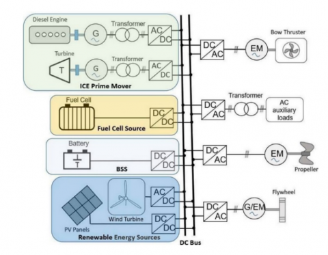
As global consciousness shifts towards environmental sustainability, reducing CO2 emissions has become a crucial initiative across all sectors. The maritime industry has promptly followed this trend, with an increasing emphasis on transitioning to electrical systems and employing sustainable technologies [1, 2]. In this context, the electrification of naval systems has emerged as a pivotal strategy in emission reduction. This has led to comprehensive studies on the development of Shipboard Power Systems (SPS) and Shipboard Microgrids (SMGs) [3], as illustrated in Figure 1. Notably, SMGs have demonstrated significant advantages over traditional AC bus solutions, including improved system efficiency, operational flexibility, component size reduction, and enhanced fault protection performance.
A key advancement in SMGs is the integration of Energy Storage Systems (ESS). ESS offers several benefits, such as spinning reserve, peak shaving, network resilience stability, and shaft generator load transfer. Additionally, ESS can serve as backup power sources during generation system failures or short periods of fault isolation. Among various ESS technologies, Battery-Based ESS (BESS) and Ultra-Capacitor-Based ESS (UC-ESS) are predominantly utilized [4].
However, challenges persist in designing systems to meet ship load cycles using a single battery technology (monotype storage). These lead to oversized designs and suboptimal use of energy sources, which ultimately impact the economic cost of the BESS [5].
A potential solution lies in the implementation of a Hybrid Energy Storage System (HESS), which interfaces different battery technologies using power electronics converters. A HESS enables more efficient use of different storage systems by preventing oversizing and optimizing energy flow [5-7].
Figure 1. The architecture of the shipboard electric power distribution with DC bus [8]
The use of HESS necessitates a Modular Battery-Converter System (MBCS) topology to achieve the required power and voltage levels for DC-SMGs. This approach involves a distributed modular BESS with hierarchical control. Each battery pack is assigned dedicated modular converters, which manage the battery's State of Charge (SOC), State of Health (SOH), and other parameters to protect the battery from deep discharge or overcharging. Managing the SOC of different types of battery modules to bring them to an equal level is crucial to ensure the effectiveness of the MBCS solution.
This paper presents the modular HESS proposed within the SEABAT project and validates its effectiveness in supplying the shipboard grid under a realistic load profile through simulations.
The paper is structured as follows: Section 2 discusses suitable battery technologies and converter structures for HESSs. Section 3 presents and describes the SEABAT topology. Section 4 presents simulation results of the SEABAT solution for realistic ship load cycles. Section 5 concludes the paper.
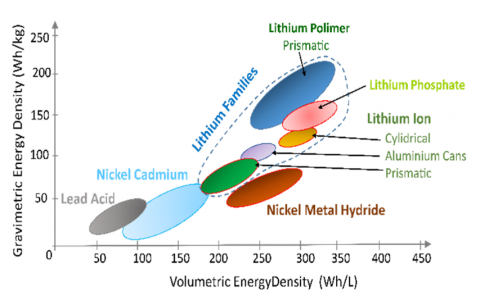
Figure 2. The volumetric and gravimetric energy density of various battery chemistries [8]
In the past, lead acid batteries were commonly used for shipboard applications due to their low self-discharge rate, high response time, and low cost. However, drawbacks such as low energy density and a complex decommissioning process due to the presence of lead have resulted in a need for alternative solutions. Lithium-ion batteries have emerged as a viable solution for modern marine applications, with various types available on the market such as Lithium-Iron Phosphate, Lithium Nickel Manganese Cobalt, and Lithium Manganese Oxide [9]. Their overview is shown in Figure 2. Lithium-ion cells typically have an open circuit voltage between 3.2 V and 3.9 V and are connected in series to form modules. These modules are then series and/or parallel connected to form battery packs according to voltage and current requirements. To be practical in marine applications, battery packs need a Battery Management System (BMS) and a Thermal Management System (TMS) [4]. The BMS serves as a connection block between the cells and the ship's power management system. By measuring relevant electrical, mechanical, and thermal parameters of the cells, the BMS controls the charge and discharge levels of the batteries at the single cell or group of cells level. This helps monitor the State of Charge (SOC) and State of Health (SOH) to ensure proper use of the battery packs [10]. Maintaining temperature control is essential to battery performance, and information about the temperature of the cells is sent from the BMS to the cooling and thermal management system of the battery pack. Large battery packs require additional control measures, such as air or liquid cooling systems. The BMS must also detect faulty cells to prevent thermal runaway and disconnection of affected packs. The BESS is composed of battery packs, BMS, cooling system, and power electronic components to manage electrical connections among the packs and external electric networks. Power converters and ancillary electromechanical devices are designed to deliver an ideal voltage source with overcurrent protection.
The power converter operates to maintain a constant output voltage, reducing oversizing of users not designed for a variable voltage supply.
In summary, lithium-ion batteries have become a practical alternative for marine applications due to their various types and benefits over traditional lead-acid batteries. With proper battery and thermal management systems in place, lithium-ion battery packs can deliver efficient and reliable power to support various marine operations.
The sizing of battery packs in waterborne applications is determined by three main requirements: maximum power, minimum stored energy, and number of required operating cycles. The maximum power requirement translates into a maximum current if an average constant output voltage is assumed, and the minimum stored energy is the amount needed for cycling between two consecutive partial or full charges. The number of required operating cycles directly correlates with the battery's lifespan and economic use. Due to technology limitations, maximum power and stored energy are usually independent parameters, resulting in an oversized battery. To reduce oversizing and cost, Hybrid Energy Storage Systems (HESS) can be implemented [5, 6, 11], composed of two or more battery packs with different characteristics.
Each pack complies with some, but not all, of the specifications, leading to a battery system that meets the overall requirements.
Sizing and integrating batteries in shipboard networks require conversion stages between the BESS and the onboard grid. The conversion stage needs to feature bidirectional operation, galvanic isolation, optimal exploitation of storage technologies, high conversion efficiency, limited volume, and weight.
Several battery integration structures are possible, and the simplest involves monotype BSS units interfaced with the shipboard power grid. The variable SOC of the battery requires power switches with a wider safe operating area that can withstand both the maximum BESS voltage and load current at BESS minimum voltage. An advancement on this structure is integrating a DC/DC stage into the BSS, regulating the output voltage of the unit and allowing modular storage solutions.
A HESS is therefore proposed, combining the specific features of different storage technologies such as High-Energy (HE) and High-Power (HP) batteries. These HESSs enable finer optimization of the battery part of the ship and have various connections and conversion structures.
To this purpose the literature reports several options [12]. Among them, the Semi-Active (SA) solutions connect the HE or HP storage to the power terminals of the HESS and interface the other technology with an intermediate DC/DC converter.
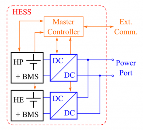
Figure 3. Full active HESS structure. All storage technologies are interfaced with an electronic converter
It leverages the best features of both technologies but does not overcome the disadvantages of having a storage device directly connected to the power port. The Full-Active (FA) HESS has each storage technology interfaced with a dedicated converter connected in parallel to a common DC bus, allowing optimal exploitation of all storage technologies, stress reduction, and lifetime extension. It can control the output voltage of the HESS unit to mitigate SOC variation, but its downsides are lower efficiency, larger volume, weight, and complexity. This latter FA solution is shown in Figure 3, and it is the topology selected for this HESS.
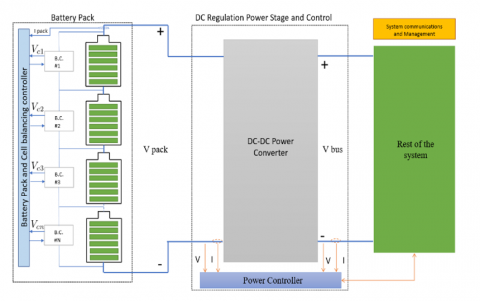
As mentioned in the introduction, a conventional monotype BESS is composed of multiple cell banks that form a matrix battery system as illustrated in Figure 4. The BESS supplies the DC bus through a centralized DC-DC bidirectional converter. The cells forming the matrix are ideally identical; however, manufacturing tolerances, self-discharge rates, uneven temperature operating across the battery cells, and non-uniform aging processes may cause mismatches. Thus, the State of Charge (SOC) of the batteries in series may diverge from one another during the charging and discharging operations, leading to an improper use of battery energy and over-discharge/overcharge problems for specific battery cells.
Figure 4. Block diagram of a monotype BESS
Figure 5. Block diagram of the HESS solution adopted by the SEABAT project [13]
Figure 6. Block diagram of the HESS control structure
Figure 7. Block diagram of the string control structure
This battery imbalance drawback may cause serious issues such as overheating, battery deterioration, and even fire, highlighting the necessity of addressing this issue [14]. To counterbalance the battery imbalance issue, cell balancing circuits are commonly utilized as an essential component of the Battery Management System (BMS). As shown in Figure 4, the DC bus voltage is controlled to the rest of the system by a power DC-DC converter. The cell is equipped with a Balancing Circuit (BC) to achieve SOC balance among the cell groups. Balancing circuits can generally be divided into two types, dissipative and energy recovery circuits. The dissipative balancing scheme consists of a shunt resistor and a switch in parallel to each battery cell or cell group, where excess energy is dissipated in the form of heat through shunt resistors.
This scheme presents low cost and easy implementation as advantages, but it reduces the efficiency of the system and the heat it generates must be dissipated. On the other hand, the energy recovery cell balancing approach can achieve balancing by exchanging excess energy between battery cells using a switched-capacitor circuit [15]. However, this scheme only transfers energy between adjacent battery cells. If energy is transferred among distant battery cells, a significant portion of energy is lost along the energy transfer path [16].
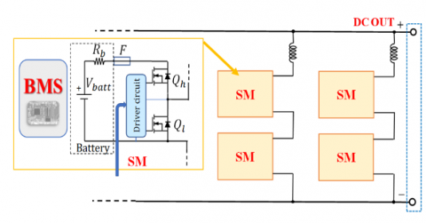
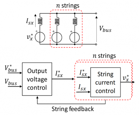
In a distributed modular BESS solution, instead of connecting the ESS through a single high-power DC-DC converter with a rated power, the storage system is decentralized into more ESSs interfaced by a lower-power DC-DC converter (with a rated power equal to a fraction of the entire HESS). As illustrated in Figure 5, the output of every sub-module (SM) is connected in series to achieve the requested DC-bus voltage $V_{\text {bus }}^*$ . A hierarchical control guarantees the proper sharing and balancing, and it is depicted in Figure 6. The master controller regulates the output voltage $V_{\text {bus }}$ of the BESS, and it shares the power between battery strings using a special algorithm based on information received from various slave modules. This is done practically by sending to each module a current reference $I_{s x}^*$, which is actuated by the string current control. This current control generates a reference voltage signal $v_x^*$ for each SM to make the measured string current $I_{s x}$ track its reference $I_{s x}^*$. The converter in every SM is a bidirectional switching cell [17] that can manage both the charging and the discharging of the battery.
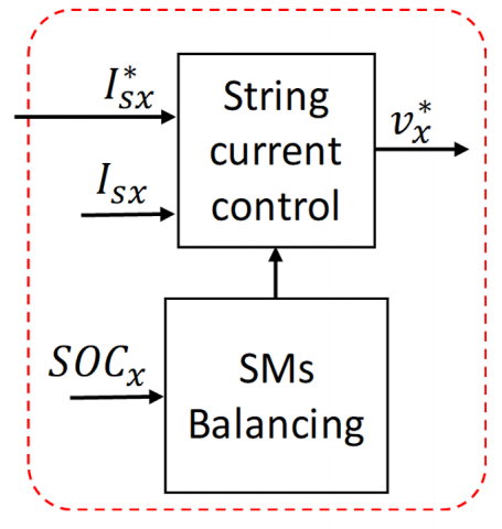
This bidirectional switching topology functions as the interface between the ESS and the rest of the system, enabling the battery to charge or discharge, depending on the case and current direction. Being this a modular structure, each SM must be balanced correctly according to its current SOC [18]. This is done through a balancing algorithm which corrects the output of the string current control according to the estimated SM $S O C_x$, as shown in Figure 7. This technique was first proposed in the study [18] and it is based on the weighted sharing of current among the various batteries. The weights quantify how much current should be absorbed by each battery according to the instantaneous estimation of its SOC and maximum capacity.
To prove the effectiveness of the proposed solution, simulations were performed in the PLECS simulation environment. PLECS is a software to simulate power electronics and dynamical systems. It features an extensive library of components (from basic electrical components to semiconductor devices and electrical machines) and an optimized mathematical solver for power electronics simulation.
The following three simulations were performed:
Simulation 1
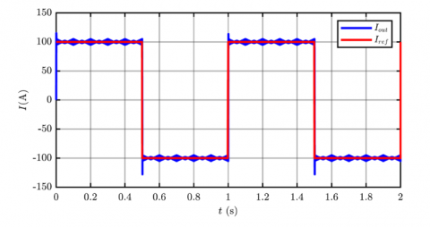
In this simulation, a single string was considered composed of 3 SMs in series. The output voltage was set to $V_{\text {bus }}^*=100 \mathrm{~V}$. For simulation purposes, the battery capacities were strongly decreased to achieve a reasonable simulation time (i.e., few seconds simulated). Three different starting SOCs (i.e., $S O C_1, S O C_2$ and $S O C_3$) are considered in the string, namely 100%, 90% and 80%. The system was loaded with the current profile of Figure 8, showing a squarewave current profile between 100A and -100A at a frequency of 1 Hz. The string output current follows the reference satisfactorily, thus correctly supplying the load, as shown in Figure 8. The SOC balance control action during the current transient is reported in Figure 9. It must be noted that despite the three batteries start with three different SOCs, the balancing algorithm can equalize them during operation. This is achieved by appropriate variation of the voltage reference of each SM.
Figure 8. Current profile of the BESS
This approach is especially useful when working with batteries of different degradation states (i.e., different capacities). Thanks to this structure and using proper balancing techniques, the system can provide the necessary current and exploit the batteries in a controlled way, without any derating due to the most degraded of them.
Figure 9. SOC profile of the three SMs during the test
Simulation 2
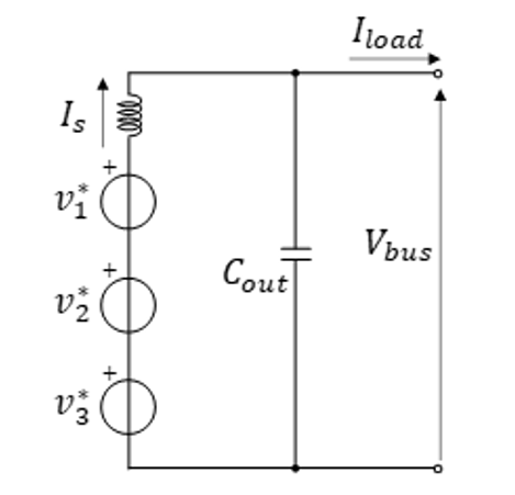
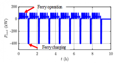
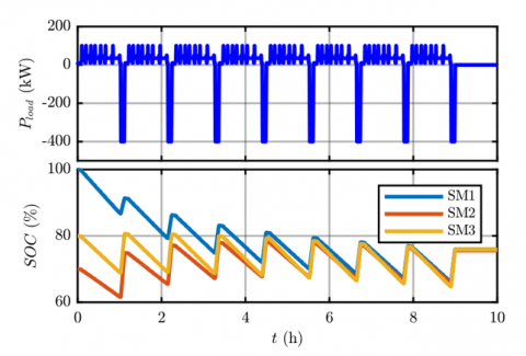
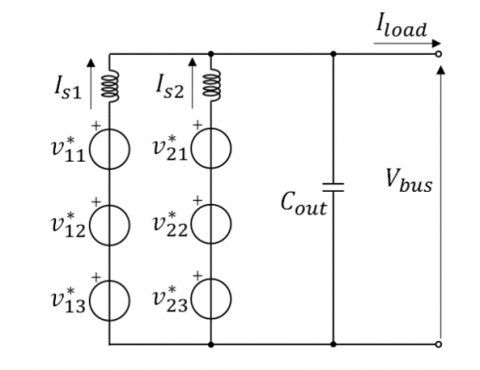
A second simulation test was run using a longer and more realistic load cycle to test the solution. In this case, the switching behavior of the DC/DC units was neglected, and the converters were modeled as ideal voltage sources. This assumption is valid, as the switching time constants (µs time scale) are much different from the load variations on the ship loads (s or minutes) and can be considered fully decoupled. The equivalent circuit for this second simulation is shown in Figure 10. To this purpose, it was necessary to include a capacitor Cout of small value to decouple the inductive circuit of the string from the current load of the ship. The presence of this capacitor is, however, not influencing the behavior of the system. In this simulation, a reference output voltage of $V_{b u s}^*=1000$ V was set, and each SM was modelled a battery with the parameters listed in Table 1 (i.e., three different batteries). The reference load cycle is shown in Figure 11, and it is taken from an electric urban ferry ship [19]. This load profile features a series of power peaks of 100 kW for the duration of roughly an hour, followed by short charging events at 400 kW. The total cycle duration is 10 h.
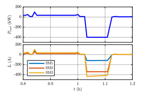
The first result is reported in Figure 12, and it shows the uneven sharing of current among the three SM batteries. The sharing is not even since the three SMs have different SOC and capacity. The current is therefore weighted differently, and some batteries will be exploited more. In this case, battery 3 will be subject to larger stress, being it larger in capacity and starting from a higher SOC.
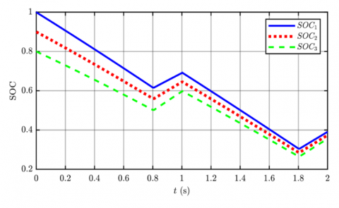
The second result is shown in Figure 13 and it highlights how the adopted balancing technique can equalize the SOC of the three SM during operation. Thanks to the non-even exploitation of the three SMs, the SOC is balanced during operation. It must be noted that this equalization is performed during operation and therefore requires either charging or discharging current to be achieved. This method cannot work if the BESS is disconnected.
Figure 10. Simplified simulation model for real load profiles
Figure 11. Urban ferry load cycle [19]
Table 1. String simulation parameters
|
SM |
$\boldsymbol{n}_s$ |
OCV (V) |
Capacity (kWh) |
SOC0 (%) |
|
1 |
174 |
400 |
22 |
100 |
|
2 |
174 |
400 |
22 |
70 |
|
3 |
115 |
419 |
159 |
80 |
Figure 12. Urban ferry load cycle: detail on the battery current sharing
Figure 13. Urban ferry load cycle: SOC trend during the cycle
Simulation 3
Figure 14. Simplified simulation model of a two-strings system for real load profiles
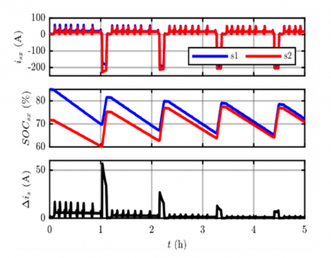
The third simulation implements the system shown in Figure 14. There are two identical strings (s1 and s2), each composed of 3 SMs, connected in parallel to supply the shipboard loads. In this case, all the batteries supplying the SMs are identical, but they start from various initial SOCs, as listed in Table 2.
This simulation demonstrates how the proposed system is also capable of supplying a given load profile while sharing the load current among multiple strings according to the balancing algorithm. This is shown in Figure 15, where the current of each string is depicted, along with the average SOC of each string and the current injection difference $\Delta i_s=i_{s 1}-i_{s 2}$ between the two strings. As the strings start from a different average SOC, the algorithm will make the string with the larger SOC injects more current and recharge less. This action leads to the balancing of the SOCs of the two strings and, finally to a more homogeneous current sharing among the two strings.
Figure 15. BESS strings currents and SOCs over a cycle
Table 2. Initial SOCs for the two-strings simulation
|
SM |
11 |
12 |
13 |
21 |
22 |
23 |
|
SOC0 (%) |
90 |
80 |
85 |
80 |
60 |
75 |
Naval electrification is currently a trending topic with large industrial and academic interest. Current solutions involve monolithic battery systems, integrating a single battery technology. However, this leads to less optimized and more expensive storage solutions. A feasible solution could be a hybrid storage system, where batteries of various technologies are integrated thanks to power electronic converters interfacing them. This kind of solution requires suitable control strategies capable of correctly balancing the SOC and the load on each of these battery technologies. To this purpose, a modular multilevel conversion structure, where each converter submodule interfaces a battery pack, seems a suitable solution. This structure guarantees a well-tailored storage system, based on the application needs, with minimal oversizing. Moreover, thanks to the power electronics interface, any storage technology can be adopted, such as batteries of various chemistries or with different age. This paper described this solution and demonstrated its effectiveness by means of simulations. The load is supplied correctly even when a multi-module and multi-string structure is adopted. The control system is also capable of balancing the exploitation of the various batteries along the operating cycle. Future work will validate this solution experimentally on a two-string prototype currently being assembled.
The research leading to these results has received funding from the European Union under grant agreement No. 963560 Horizon 2020 SEABAT - "Solutions for largE bAtteries for waterBome trAnsporT". The authors would like to thank Mr. Simone Mongelli for the help with the simulations.
|
BSS |
Battery storage system |
|
BESS |
Battery energy storage system |
|
HESS |
Hybrid energy storage system |
|
BMS |
Battery management system |
|
ESS |
Energy storage system |
|
SOC |
State of charge |
|
SM |
Submodule |
|
SPS |
Shipboard power systems |
|
SMG |
Shipboard microgrids |
|
OCV |
Open circuit voltage |
|
FA |
Fully active |
|
SA |
Semi active |
|
HE |
High energy |
|
HP |
High power |
|
MBCS |
Modular battery-converter system |
|
TMS |
Thermal management system |
|
Subscripts and Superscripts |
|
|
0 |
Simulation starting value |
|
s |
Value of a certain string |
|
* |
Reference value |
[1] Paul, D. (2020). A history of electric ship propulsion systems. IEEE Industry Applications Magazine, 26(6): 9-19. https://doi.org/10.1109/MIAS.2020.3014837
[2] Aijjou, A., Bahatti, L., Raihani, A. (2020). Analysis of container ship energy systems. International Journal of Energy Production and Management, 5(2): 142-156. https://doi.org/10.2495/EQ-V5-N2-142-156
[3] Rahimi-Eichi, H., Ojha, U., Baronti, F., Chow, M.Y. (2013). Battery management system: An overview of its application in the smart grid and electric vehicles. IEEE industrial electronics magazine, 7(2): 4-16. https://doi.org/10.1109/MIE.2013.2250351
[4] Cao, J., Emadi, A. (2012). A new battery/ultracapacitor hybrid energy storage system for electric, hybrid, and plug-in hybrid electric vehicles. IEEE Transactions on Power Electronics, 27(1): 122-132. https://doi.org/10.1109/TPEL.2011.2151206
[5] Akbarzadeh, M., De Smet, J., Stuyts, J. (2022). Battery hybrid energy storage systems for full-electric marine applications. Processes, 10(11): 2418. https://doi.org/10.3390/pr10112418
[6] Tao, Z., Barrera-Cardenas, R., Akbarzadeh, M., Mo, O., De Smet, J., Stuyts, J. (2023). Design and evaluation framework for modular hybrid battery energy storage systems in full-electric marine applications. Batteries, 9(5): 250. https://doi.org/10.3390/batteries9050250
[7] Barrera-Cardenas, R., Mo, O., Guidi, G. (2019). Optimal sizing of battery energy storage systems for hybrid marine power systems. In 2019 IEEE Electric Ship Technologies Symposium (ESTS), IEEE, pp. 293-302.
[8] Pastorelli, M., Musumeci, S., Mandrile, F. (2021). Battery sources and power converters interface in waterborne tansport applications. In 2021 AEIT International Conference on Electrical and Electronic Technologies for Automotive (AEIT AUTOMOTIVE), IEEE, pp. 1-5. https://doi.org/10.23919/AEITAUTOMOTIVE52815.2021.9662776
[9] Kim, T., Song, W., Son, D.Y., Ono, L.K., Qi, Y. (2019). Lithium-ion batteries: Outlook on present, future, and hybridized technologies. Journal of Materials Chemistry A, 7(7): 2942-2964. https://doi.org/10.1039/C8TA10513H
[10] Rivera-Barrera, J.P., Muñoz-Galeano, N., Sarmiento-Maldonado, H.O. (2017). SoC estimation for lithium-ion batteries: Review and future challenges. Electronics, 6(4): 102. https://doi.org/10.3390/electronics6040102
[11] Akbarzadeh, M., De Smet, J., Stuyts, J. (2022). Cost assessment of battery hybrid energy storage system for full-electric marine applications. In 2022 22nd International Scientific Conference on Electric Power Engineering (EPE), IEEE, pp. 1-6. https://doi.org/10.1109/EPE54603.2022.9814114
[12] Zimmermann, T., Keil, P., Hofmann, M., Horsche, M.F., Pichlmaier, S., Jossen, A. (2016). Review of system topologies for hybrid electrical energy storage systems. Journal of Energy Storage, 8: 78-90. https://doi.org/10.1016/j.est.2016.09.006
[13] Mandrile, F., Pastorelli, M., Musumeci, S., Urkiri, I.A., Remirez, A. (2023). Second life management from battery storage system of electric waterborne transport applications: Perspectives and solutions. IEEE Access. https://doi.org/10.1109/ACCESS.2023.3265168
[14] Bandhauer, T.M., Garimella, S., Fuller, T.F. (2011). A critical review of thermal issues in lithium-ion batteries. Journal of the Electrochemical Society, 158(3): R1. https://doi.org/10.1149/1.3515880
[15] Sani, A., Hu, C.K., Hsieh, Y.C., Chiu, H.J., Lin, J.Y. (2016). Switched-capacitor charge equalization circuit for series-connected batteries. In 2016 IEEE 2nd Annual Southern Power Electronics Conference (SPEC), IEEE, pp. 1-5. https://doi.org/10.1109/SPEC.2016.7846016
[16] Ye, Y., Cheng, K.W.E. (2016). An automatic switched-capacitor cell balancing circuit for series-connected battery strings. Energies, 9(3): 138. https://doi.org/10.3390/en9030138
[17] Abdelhakim, A., Mattavelli, P., Pistollato, S., Spiazzi, G. (2018). Bidirectional DC-DC converter topologies for low-voltage battery interface: Comparative assessment. In 2018 IEEE 4th International Forum on Research and Technology for Society and Industry (RTSI), IEEE, pp. 1-6. https://doi.org/10.1109/RTSI.2018.8548433
[18] Mukherjee, N., Strickland, D. (2014). Control of second-life hybrid battery energy storage system based on modular boost-multilevel buck converter. IEEE Transactions on Industrial Electronics, 62(2): 1034-1046. https://doi.org/10.1109/TIE.2014.2341598
[19] D2.1–Application matrix. https://seabat-h2020.eu/download/SEABAT_D2.1_Application-Matrix_PU_2021-08-27-v1.0-FINAL.pdf, accessed on Feb. 6, 2023.