Hayder M. Ali![]() | Louay A. Mahdi*
| Louay A. Mahdi*![]()
© 2023 IIETA. This article is published by IIETA and is licensed under the CC BY 4.0 license (http://creativecommons.org/licenses/by/4.0/).
OPEN ACCESS
In the present work, exergy analysis has been experimentally evaluated for a chest freezer to assist in sizing calculations and selecting the most suitable working fluid, which can reduce the power consumption. In the present work, exergy analysis has been experimentally evaluated for a chest freezer to assist in sizing calculations and selecting the most suitable working fluid to reduce power consumption. The experimental measurements were carried out using a 150 litters chest freezer volume capacity running on R-134a and R-600a using different compressors. The freezer provides measurement instruments for pressure, temperature, refrigerant mass flow and power consumption. The tests were carried out with a standard ambient temperature of 32. The results show that the evaporator had the highest exergy loss value of 59% for R-134a and 62% for R-600a. Compressor exergy losses are 64% for R-134a and 63% for R-600a. The condenser showed exercise losses of 79% for R-134a and 75% for R-600a, while the limitation device (capillary tube) had exercise losses of 87% for R134a and 99.5% for R-600a. The thermal performance of the chest freezer represented by the second low efficiency is 43% for R-134a and 50% for R-600a. The thermal performance of the freezer with R-600a is better than R-134a due to the energy consumption reducing and evaporator behaviour.
exergy analysis, chest freezer, second low efficiency, COP, refrigerants
Refrigeration operates widely in the domestic and commercial sectors for food preservation. One of these applications is the chest freezer. A chest freezer is mainly designed for stocking frozen food products in massive quantities.
Bejan [1] performed a theoretical analysis of the refrigeration system. Two cases were explained. The first was concerned with modeling a refrigeration plant, and its irreversibility was mainly attributable to the internal heat transfer flows directly through the system. The second was based on three heat transfer types: internal heat transfer, the temperature differential between the refrigeration plant and ambient externally, and the temperature difference between the refrigeration load and the refrigeration plant's cold end. Xu and Clodic [2] conducted theoretical and experimental exergetic analysis on three refrigerators/freezers working with different refrigerants (R12, R134a and R290). The results show that most exergy losses occur in the compressor and evaporator and then in the condenser and throttling device. Vincent and Heun [3] explore and optimize the term economics of domestic refrigerators from an exergy perspective during steady-state operation. They found that the energy efficiency ratio of the compressor has the most significant impact on the performance and economy of the system. Also, the cost of cooling depends on the cost of the compressor.
Bayrakçi and Özgür [4] compared the energy and exergy performance of refrigerators with four different refrigerants, R290, butane R600, isobutane R600a, and isopentane R1270. R22 and R134a were also used in their analysis. The results show that under all working conditions, the energy and energy efficiency of R1270 reach the maximum. However, the same efficiency can be obtained with R600. Ahmed et al. [5] performed theoretical energy and exergy analysis of domestic refrigerators working with pure refrigerants: butane (R600) and isobutene (R600a) that are compared with R134a. The exergy efficiency of isobutene as a refrigerant is 50% greater than that of R-134a. Moreover, exergy loss in the compressor is more extensive than in other parts of the system. Stanciu et al.’s [6] exergy comparison of the refrigerants R22, R134a, R717, R507a and R404a showed how they affect the operation and performance of a domestic refrigerator system. The highest exergy loss rate was in the compressor, and the lowest was in the throttling device for all refrigerants.
Radha et al. [7] tested a 400-l chest freezer using the refrigerant R134a. The cooling load estimates the needed compressor capacity. According to ASHRAE design operating conditions in 1977, the design assumption is 52% heat loss due to walls, gaskets and air change load taking 30% heat loss and miscellaneous like foodstuffs, defrosting radiant heaters, fans, and thermostats cover 18%. Their results reveal that while designing a refrigeration system for a freezer, strict requirements ensure that the system's quality and adaptability are not compromised. The freezer placement is also crucial in lowering the strain on the system.
Joybari et al. [8] exergy analysis was applied to investigate the performance of a domestic refrigerator originally manufactured working with R134a and R600a to limit exergy destruction. The analysis found that the quantity of charge necessary for R600a is 66% less than the amount necessary for R134a. Exergy destruction is 45% of the base refrigerator one in optimal conditions. Ansari et al. [9] performed a theoretical exergy analysis of HFO-1234yf and HFO-1234ze as an alternative replacement for HFC-134a in a simple vapor compression refrigeration system. Gaurav [10] compared energy and exergy analysis for refrigerators working with several refrigerants. The results had the most significant value of exergy destruction and efficiency defect in the compressor for the refrigerants. In contrast, the condenser has the greatest efficiency, followed by the throttle valve and evaporator. Malwe et al. [11] performed analytical and experimental tests for cold refrigeration rooms working with R12 using the exergy analysis technique. It was discovered that the system's second law efficiency is 58%. This might be due to gas leakages, internal irreversibility in the system, and component-wise exergy losses. The compressor has the lowest exergy efficiency score because it uses non-isentropic compression. Furthermore, is known that the evaporator's exergy losses decrease at lower pressures and temperatures.
McGovern and Oladunjoye [12] studied the exergetic analysis of domestic refrigerators working with refrigerant R600a. The compressor exergy efficiency was 42.9%, while the cycle exergy efficiency was 34.8%. Yadav and Sharma [13] performed an experimental exergetic analysis of a refrigerator system working with R134a. The results reveal that the most extensive energy destruction occurs in the condenser, followed by the compressor, the throttling device, and the evaporator. Also, the whole system's exergetic efficiency is 35.23%. Prakash et al. [14] presented a theoretical energy and exergy performance of refrigerators working with a mixture of refrigerants. The results show that the compressor has the highest irreversibility, followed by the evaporator, expansion valve, and condenser.
Mishra and Khan [15] performed a theoretical exergy analysis of refrigerators working with several types of refrigerants. The results show that the condenser is the poorest component in irreversibility, followed by the throttling device, evaporator and compressor. Tiwari et al. [16] also performed a theoretical exergy analysis of domestic refrigerators working with different refrigerants. R600 has the highest exergy efficiency at low evaporator temperatures than others. The compressor has the highest irreversibility, followed by the condenser, throttling device, and evaporator. Mahdi et al. [17] performed an experimental study as well as energy and exergy thermodynamic analysis for a domestic refrigerator working with refrigerant R-134a. They determined that the compressor had the lowest exergy efficiency of 25%. While the throttling device has a 92% exergy efficiency and the condenser has a 93% efficiency, the evaporator has a 98% exergy efficiency. Gill et al. [18] experimentally studied the exergetic performance of refrigerator systems working with R450a and R134a at high to low temperatures within controlled environmental conditions. The result was that the overall irreversibility of the R450A system was lower than that of the R134a system. The exergy efficiency of the R450A system is higher than that of the R134a system.
Chest freezers are standard and widely used in restaurants and houses. The chest freezer work with a vapor compression refrigeration cycle. The main parts of the vapor compression refrigeration cycle are the compressor, condenser, throttling device and evaporator. The open literature does not cover the energy and exergy analysis for the chest freezer. Most of the research covers thermodynamic and exergy analysis studies for domestic refrigerators. In the present work, thermodynamic and exergy analyses are performed for the chest freezer. The experimental work was carried out using a 150-l chest freezer, which works with R-134a and R-600a. The objective is to find the work points of lower energy consumption of the freezer safe to assist in the sizing.
2.1 Test apparatus
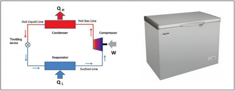
The experimental test was performed using a chest freezer of 150-l internal volume, the most common type used by houses and restaurants in Iraq. The chest freezer and the operational cycle are shown in Figure 1.
Figure 1. The chest freezer and basic vapor compression refrigeration cycle
Figure 2. a. Schematic diagram of the refrigerant piping system b. The actual tubing system of the chest freezer and the locations of the thermocouple wires
The condenser is a wire-on tube type of iron steel black paint to improve the outside heat transfer by natural convection and radiation. The equivalent length of the condenser is 10.5 m, the diameter of the tube 1/4" (6.35 mm), and the wire fin diameter 1.2 mm. The first reciprocating compressor working with R-134a is a Konor brand GQR60AA model, and the second working with R-600a is DONGER brand GD59N. The copper capillary tube is welded outside the suction line of the compressor using a throttling device. The evaporator is built of copper tube, its diameter is 5/16" (7.937 mm), warp around the evaporator box of the internal compartment, and the circuit has a total length of 15 m. The schematic and existing tubing system of the tested chest freezer is shown in Figure 2. The type of refrigerants is chosen close to AHRI-700 standard, suitable for working at lower evaporator temperatures less than –23.3℃.
2.2 Measurement system
Type-T thermocouples were used to measure the temperatures with an accuracy of ±1℃. Thirteen thermocouples were attached to the tube of wire condenser at the middle of the legs, and seven thermocouples for the evaporator for each loop of tubes, as shown in Figure 2b. Pressures were measured at the low sides (evaporator inlet/outlet) and high sides (condenser inlet/outlet) by four transducer types. The accuracy of the transducer was ±0.5%, as declared by the manufacturer. A power analyzer has been used to measure the electric power consumption with an accuracy of ±3% for the power, ±2% for the current, and ±1.2% for the voltage. The tests were performed inside a climatic room built according to the specifications of ASHRAE committee 8.99.
Exergy is the maximum useful work obtained from the system at a given state in a specified environment. A method that uses the second law of thermodynamics and the conservation of mass and energy to design and analyze the thermal system helps identify the processes and efficiencies. The entropy generation is a measure of the inequality sign in the second law and represents the irreversibility of the process. For the refrigeration system, the exergy supplied is the power input. Converting the maximum fraction of heat to work requires an entirely reversible engine. For steady-state process over a control volume, the equation for total exergy destruction, according to the studies [19, 20], is:
Total exergy destruction=Net exergy transfer by heat +Net exergy transfer by work +Net exergy transfer by mass flow (1)
$E D=\sum\left(1-\frac{T_o}{T_s}\right) \dot{Q}-(\dot{W})+\dot{m} \cdot \sum_{\text {in }} E x+\dot{m} \cdot \sum_{\text {out }} E x$ (2)
where,
$E x=\left[\left(h-h_o\right)-T_o *\left(s-s_o\right)\right]$ (3)
All symbols appearing in the equations of this section are defined under “Nomenclature” at the end of the paper.
The Carnot coefficient of performance (COP) of the system is:
$C O P_{c a r n o t}=\frac{T_{e s a t}}{T_{c s a t}-T_{e s a t}}$ (4)
The second law of efficiency of the system is:
$\eta_{\Pi}=\frac{C O P}{C O P_{\text {carnot }}}$ (5)
3.1 Compressor modelling
The compressor's power input is the work's summation and the power required to overcome the friction and heat losses to the surrounding [17, 18]. It can be expressed in the form:
$P=W+Q_{\text {total losses }}$ (6)
where,
$W=\dot{m}_r *\left(h_2-h_1\right)$ (7)
$Q_{\text {total losses }}=Q_{\text {conv. }}+Q_{\text {rad. }}+Q_{\text {friction }}$ (8)
The energy balance gives:
$\dot{m}_r * \sum_{\text {in }} h_1+$ Power $=\dot{m}_r * \sum_{\text {out }} h_2+Q_{\text {losses }}$ (9)
The exergy destruction (ED) can be obtained from the exergy balance as follows:
$E D_{\text {comp }}=\left(1-\frac{T_{a m b}}{T_{\text {shellcomp }}\quad}\right) Q_{\text {total losses }}-Power+\sum_{\text {in }} E x-\sum_{\text {out }} E x$ (10)
where,
$\sum_{i n} E x=m_r^{\cdot} * e x_1=m_r^{\cdot} *\left\{\left(h_1-h_o\right)-T_o *\left(S_1-S_o\right)\right\}$
$\sum_{\text {out }} E x=m_r^{\cdot} * e x_2=m_r^{\cdot} *\left\{\left(h_2-h_o\right)-T_o *\left(S_2-S_o\right)\right\}$
Dissipation in the compressor:
$\zeta_{\text {comp }}=\frac{E D_{\text {comp }}}{P}$ (11)
Exergy efficiency:
$\eta_{\Pi}=\eta_{e x \operatorname{comp}}=1-\zeta_{c o m p}$ (12)
3.2 Wire on tube condenser modelling
The analysis is based on suggested relations by the authors of the studies [17, 21]. The energy balance across the condenser is:
$\dot{m}_r \cdot h_2+\dot{m}_a \cdot h_{a i n c}=\dot{m}_r \cdot h_3+\dot{m}_a \cdot h_{\text {aout }}+Q_{\text {con losses }}$ (13)
$\mathrm{Q}_{\text {cond losses }}=\dot{m}_r \cdot\left(h_2-h_3\right)-\dot{m}_a \cdot\left(h_{\text {ainc }}-h_{\text {aoutc }}\right)$ (14)
The exergy analysis is performed using:
$E D_{\text {cond }}=\left(1-\frac{T_{\text {amb }}}{T_{\text {wallcond }}\quad}\right) \mathrm{Q}_{\text {cond losses }}+\Sigma_{\text {in }} \mathrm{ex}-\Sigma_{\text {out }} \mathrm{ex}$
where,
The final form for the exergy in the condenser unit is:
$E D_{\text {cond }}=\left(1-\frac{T_{\text {amb }}}{T_{\text {wall cond }} \quad}\right) \cdot \mathrm{Q}_{\text {cond losses }}+\dot{m}_r \cdot\left[\left(e x_2-e x_3\right)+\frac{\Delta P_{2-3 \text { cond }}}{\rho_2} \quad \right]+\dot{m}_a \cdot\left(e x_{a i n c}-e x_{a o u t c}\right)$ (15)
Dissipation in the condenser:
$\zeta_{\text {cond }}=\frac{E D_{\text {cond }}}{P_{\text {total }}}$ (16)
The exergy efficiency is given by:
$\eta_{\text {cond }}=1-\zeta_{\text {cond }}$ (17)
3.3 Throttling device modelling
From the energy balance, the thermodynamic equation of the throttling process for steady-state has no work or heat loss or added [18]. Then, $h_3=h_4$.
$E D_{\text {throttling }}=\left(1-\frac{T_o}{T_w}\right) Q_{3-4}+\dot{m}_r \cdot \sum_{i n}\left[e x_3+\frac{P_3}{\rho_3}\right]-\dot{m}_r \cdot \sum_{\text {out }}\left[e x_4+\frac{P_4}{\rho_4}\right]$ (18)
where,
Since $\left(1-\frac{T_o}{T_w}\right) Q_{3-4}=0$ and W=0, then the final form of exergy across the throttle device is given by
$\left.E D_{\text {throttling }}=\dot{m}_r \cdot\left[\left(T_o \cdot\left(S_4-S_3\right)\right)+\frac{\Delta P_{3-4}}{\rho_3}\right)\right]$ (19)
Dissipation in the throttling device:
$\zeta_{\text {throttling }}=\frac{E D_{\text {throttling }}}{P_{\text {total }}}$ (20)
The exergy efficiency is given by
$\eta_{\text {throttling }}=1-\zeta_{\text {throttling }}$ (21)
3.4 Tube on plate evaporator modelling
The energy balance is given as:
$\dot{m}_r \cdot h_1+\dot{m}_a \cdot h_{\text {aine }}=\dot{m}_r \cdot h_4+\dot{m}_a \cdot h_{\text {aoute }}+Q_{\text {evap losses }}$
$Q_{\text {evap losses }}=\dot{m}_r \cdot\left(h_1-h_4\right)-\dot{m}_{\text {aevap }} \cdot\left(h_{\text {ainevap }}-h_{\text {aoutevap }}\right)$ (22)
The exergy balance is given as:
$E D_{\text {evap }}=\left(1-\frac{T_{a e}}{T_{\text {wallevap }} \quad}\right) Q_{\text {evap losses }}+\sum_{\text {in }} e x-\sum_{\text {out }} e x$ (23)
where,
The final form for the exergy destruction is:
$E D_{\text {evap }}=\left(1-\frac{T_{a e}}{T_{\text {wallevap }} \quad}\right) Q_{\text {evap losses }} +\dot{m}_r \cdot\left[\left(e x_4-e x_1\right)+\frac{\Delta P_{4-1 \text { cond }}}{\rho_4} \quad \right]+\dot{m}_a \cdot\left[\left(e x_{\text {aine }}-e x_{\text {aoute } \quad}\right)+\frac{\Delta P_{\text {aevap }}}{\rho_{\text {ainevap }} \quad}\right]$ (24)
Exergy dissipation:
$\zeta_{\text {evap }}=\frac{E D_{\text {evap }}}{P_{\text {total }}}$ (25)
The exergy efficiency is given by:
$\eta_{\text {evap }}=1-\zeta_{\text {evap }}$ (26)
The p-h and T-s diagrams for the tests are presented in Figures 3 and 4 for R-134a and R-600a, respectively. The tests for the chest freezer system were carried out at 32℃ ambient temperature.
4.1 Analysis of experimental results
The p-h and T-s diagrams for the tests are presented in Figures 3 and 4 for R-134a and R-600a, respectively. The tests for the Chest freezer system done at 32℃ ambient temperature. Figure 3a explains the refrigerant R-134a cycle which is close to the condenser and evaporator's standard refrigerant temperature in the studies [22, 23]. The compressor works in the superheat region, and the process is not isentropic. It is usually deviated due to its irreversibility, that means a reduction in isentropic and volumetric efficiency. The throttling process start working (inlet) at the end of the subcooled region of the condenser. The subcooling done by (∆T=3℃) which is helping to improve the cycle, while the outlet condition of the throttling process is still away from the low value of dryness friction the quality x=0.43.
The T-s diagram for R-134a is the second plot in Figure 3. As an exception to the refrigerant cycle, two horn areas have appeared. These hatchet areas represent waste heat that cannot be controlled. The compressor horn happens due to the discharge temperature above the condenser saturation temperature. In contrast, the other horn at the throttling process, due to the irreversibility, in this case, increases in dryness fraction to the right, which means reducing the cooling capacity.
Figure 3. p-h & T-s diagrams of vapor compression refrigeration cycle of chest freezer working with R-134a –steady state
The first diagram in Figure 4 explains that the refrigerant R-600a works at less than the standard refrigerant temperature [19]. The condenser drops two degrees lower than the saturation temperature and the evaporator five degrees lower. The compressor works in the superheat region like the R-134a. The throttling process starts working (inlet) at the end of the subcooled region of the wire on the tube condenser, and the saturation temperature drop by ∆T=5℃, leading to outlet conditions for quality x=0.33, which helps to improve the cycle by increasing the evaporation process. The T-s diagram for R-600a in Figure 4 shows the compressor horn area for R-600a, which is less than that for R-134a, which means low power consumption for R-600a. Also, the throttling process horn area is almost non-existent due to the refrigerant flow in the capillary tube.
Figure 4. P-h & T-s diagrams of vapor compression refrigeration cycle of chest freezer working with R-600a–steady state
4.2 Exergy analysis
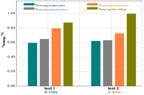
Figure 5 shows the exergy analysis for compressors, evaporator, throttling device, and wire on tube condenser for the chest freezer. The tests were done at 32℃ ambient temperatures with two types of refrigerants, R-134a and R-600a. The first column is for the evaporator exergy, which is the lowest value due to the external and internal heat losses of 59% for R-134a and 62% for R-600a. The losses happen due to the lower value of the evaporator temperature than the ambient temperature. The compressor's exergy is 63% for R-600a and 64% for R-134a, and the losses represent 37% for R-600a and 36% for R-134a. The losses are due to friction and heat losses by convection and radiation to the environment. The third column is for the wire on the tube condenser. The results agree with those presented in the study [14], which show that compressor's exergy losses are around 44%. The exergy efficiency for the condenser work with R-134a (79%) is higher than that for condenser work with R-600a (75%). The reason is due to the lower refrigerant temperature difference with ambient which causes a drop in the heat transfer coefficient for R-600a. The last column is for the throttling device exergy efficiency, which gets a higher value of 87% for the cycle of R-134a and 99.5% for cycle work with R-600a. The throttling device (capillary tube) exergy for R-134a is lower than the throttling device exergy for R-600a, and the reason is that the surface tension of the refrigerant R-600a is higher than the surface tension of the refrigerant R-134a, which act on the mass flow rate for the cycle working with R-600a.
The losses for the chest freezer at the evaporator, compressor, condenser, and throttling device are from the higher to the lower value, respectively.
The significant change in the exergy is taking place in the evaporator for three main reasons. First, the lower space temperature required in the freezer creates a high-temperature difference between the inside and the ambient temperature; second, the type of evaporator tube on a plate takes a lower performance than the roll bond type, for example. Third, the insulation type may need to change to reduce the external losses. The other component, compressor, condenser, and throttling device, work with accepted exergy losses for the other system.
Figure 5. The exergy analysis for compressors, evaporator, throttling device, and condenser of the thermal cycle of a chest freezer for all tests
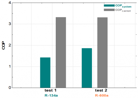
Figure 6 represents the coefficient of performance (COP) for Carnot and the experimental chest freezer for all tests. The Carnot coefficient of performance (COP) for the chest freezer is 3.2 for all tests because it depends only on the condenser and evaporator refrigerant temperatures, as in Eq. (4). The actual chest freezer cycle efficiency working with R-134a is 1.45 and 1.8 for R-600a. The difference is that the power consumption for R-134a is higher than the power for R-600a.
Figure 6. The coefficient of performance (COP) and COP Carnot of the thermal cycle of a chest freezer for all tests
Figure 7 shows the chest freezer's thermodynamic, isentropic and volumetric efficiencies for all tests. The second law efficiency for the R-134a cycle is 43% and 50% for R-600a. The difference happens due to the lower power consumption for R-600a. The second law efficiency is around the value of the same thermal system. The volumetric efficiency for R-134a (41%) is lower than that for R-600a, which is 60%, due to the cycle's high-pressure ratio, which was confirmed by Groll [22] and to the difference in the specific volume of the refrigerants. This result agrees with that in the study [11], but is down more due to the irreversibility increase in the evaporator. The isentropic efficiency is around 65% for the cycle of R-134a, which is lower than that for R-600a, 70%, due to the irreversibility of the compression process.
Figure 7. Comparison between the chest freezer's thermodynamic, isentropic, and thermal cycle efficiencies works with R-134a and R-600a
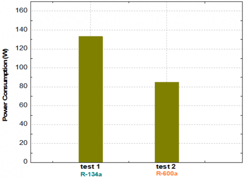
Figure 8 allows a comparison of the chest freezer's power consumption when working with R-134a and R-600a fluids. The power consumption for the thermal cycle of R-134a is 133 W, which is higher than the power consumption of R-600a, 85 W, due to the higher refrigerant mass flow rate for R-134a being higher than the refrigerant mass flow rate of R-600a.
Figure 8. The power consumption of the chest freezer works with R-134a and R-600a
4.3 Solar PV prediction
The required solar PV to maintain the chest freezer operation in non-interrupted mode is predicted based on the measured power consumption. The number of the required PV modules is based on the suggested procedure by Mohammad and Ismael [23].
The solar power to be generated by the PV could be estimated by the equation:
$P_{P V}=\frac{P_{\text {total }}}{P S H \times \eta_R \times \eta_{\text {in }}} \times S F$ (27)
where, $P_{P V}$ is the required power generated from the PV modules, $P_{\text {total }}$ is the power consumption by the chest freezer in kW.h/day; PSH is Iraq's yearly mean peak solar hour, equal to 8.7 h/day; $\eta_R$ and $\eta_{i n}$ are the charge regulator efficiency, around 0.9, and inverter efficiency, around 0.9, respectively. The safety factor considered here is 1.4, which is a bit high to account for the frequent dusty storms and the high accumulated dust on the PV panels.
With the determined power consumption of the chest freezer of 133 W when operating with R-134a and 85 W when operating with R-600a, the needed power from PV is 7.88 and 5.037, respectively.
If 250 W panels are selected, then:
The predicted number of panels for a chest freezer operating with R-134a is 2.48, or 3.
The predicted number of panels for a chest freezer operating with R-600a is 1.6, or 2.
The prediction shows that selecting R-600a requires fewer 250 W PV panels than those required when selecting R-134a.
Energy and exergy analysis is performed for the thermal cycle of a chest freezer working with two types of refrigerants (R-134a and R-600a) experimentally. The essential points are:
• The evaporator has the lowest exergy value compared with the other parts (compressor, condenser, and throttling device). The efficiency value is 59% for cycle work with R-134a and 62% for R-600a. The significant heat losses from the system are in this part caused by the high-temperature difference between the freezer box and the environment.
• The compressor exergy efficiency values are 63% for the cycle work with R-600a and 64% for R-134a. That part is the second in the arrangement of the lower exergy value.
• The condenser exergy efficiency value is 79% for the cycle work with R-134a and 75% for R-600a. The condenser with these exergy values is the third in the arrangement.
• The throttling device has the highest exergy efficiency value of 87% for cycle working with R-134a and 99.5% for R-600a.
• The coefficients of performance for cycle working with R-134a are 1.43 and 1.8 for R-600a.
• The second law efficiency for a cycle working with R-134a is 43% and 50% for R-600a. The isentropic efficiency for the system work with R-600a is 70%, higher than 65% for R-134a. Also, the volumetric efficiency value is 41% for the system working with R-134a and 60% for R-600a.
• The power consumption for the thermal cycle of R-134a (133 W) is higher than that of R-600a (85 W).
• The required 250W PV panels for steady operation of the chest freezer 24 h/day are 3 panels for the case of R-134a and 2 panels for the case of R-600a working fluids.
|
Symbol |
Definition |
Unit |
|
|
COP |
Coefficient of performance |
- |
|
|
ED |
Exergy destruction |
W |
|
|
Ex |
Exergy |
W |
|
|
h |
Enthalpy |
kJ/kg |
|
|
hfg |
Latent heat |
kJ/kg |
|
|
$\dot{m}$ |
Mass flow rate |
kg/s |
|
|
P |
Power |
W |
|
|
p |
Pressure |
kPa |
|
|
$\dot{Q}$ |
Heat transfer rate |
W |
|
|
s |
Entropy |
kJ/kg. K |
|
|
T |
Temperature |
K or ℃ |
|
|
W |
Work |
W |
|
|
x |
Quality |
- |
|
|
Greek characters |
|||
|
η |
Efficiency |
|
|
|
ηII |
Second law efficiency |
|
|
|
$\rho$ |
Density |
kg/m³ |
|
|
$\zeta$ |
Exergy dissipation |
|
|
|
Subscripts |
|||
|
1 |
Inlet compressor outlet evaporator |
||
|
2 |
Outlet compressor inlet condenser |
||
|
3 |
Outlet condenser/inlet throttling |
||
|
4 |
Outlet throttling/inlet evaporator |
||
|
a |
Air |
||
|
ainc |
Air inlet condenser |
||
|
aoutc |
Air outlet condenser |
||
|
amb |
Ambient |
||
|
esat |
Evaporator saturation |
||
|
cond |
Condenser |
||
|
comp |
Compressor |
||
|
conv |
Convection |
||
|
csat |
Condenser saturation |
||
|
evap |
Evaporator |
||
|
in |
Inlet |
||
|
out |
Outlet |
||
|
r |
Refrigerant |
||
|
rad |
Radiation |
||
|
tot |
Total |
||
|
Abbreviations |
|||
|
ASHRAE |
American Society of Heating, Refrigerating, and Air-Conditioning Engineering |
||
|
AHRI |
Air-Conditioning, Heating, and Refrigerating Institute |
||
[1] Bejan, A. (1989). Theory of heat transfer-irreversible refrigeration plants. International Journal of Heat and Mass Transfer, 32(9): 1631-1639. https://doi.org/10.1016/0017-9310(89)90045-8
[2] Xu, X., Clodic, D. (1992). Exergy analysis on a vapor compression refrigerating system using R12, R134a and R290 as refrigerants. International Refrigeration and Air Conditioning Conference, Article ID: 160, pp. 231-240.
[3] Vincent, C.E., Heun, M.K. (2006). Thermoeconomic analysis & design of domestic refrigeration systems. In Domestic use of energy conference.
[4] Bayrakçi, H.C., Özgür, A.E. (2009). Energy and exergy analysis of vapor compression refrigeration system using pure hydrocarbon refrigerants. International Journal of Energy Research, 33(12): 1070-1075. https://doi.org/10.1002/er.1538
[5] Ahamed, J.U., Saidur, R., Masjuki, H.H. (2010). Thermodynamic performance analysis of R-600 and R-600a as refrigerant. Engineering e-Transaction, 5(1): 11-18.
[6] Stanciu, C., Gheorghian, A., Stanciu, D., Dobrovicescu, A. (2011). Exergy analysis and refrigerant effect on the operation and performance limits of a one stage vapor compression Refrigeration system. Termotehnica, 1: 36-42.
[7] Radha, K.K., Sarada, S.N., Rajagopal, K. (2012). Development of a chest freezer–optimum design of an evaporator coil. International Journal of Automotive and Mechanical Engineering, 5: 597-611. https://doi.org/10.15282/ijame.5.2012.6.0047
[8] Joybari, M.M., Hatamipour, M.S., Rahimi, A., Modarres, F.G. (2013). Exergy analysis and optimization of R600a as a replacement of R134a in a domestic refrigerator system. International Journal of refrigeration, 36(4): 1233-1242. https://doi.org/10.1016/j.ijrefrig.2013.02.012
[9] Ansari, N.A., Yadav, B., Kumar, J. (2013). Theoretical exergy analysis of HFO-1234yf and HFO-1234ze as an alternative replacement of HFC-134a in simple vapour compression refrigeration system. International Journal of Scientific & Engineering Research, 4(8): 137-144.
[10] Gaurav, R.K. (2014). Performance analysis of household refrigerator with alternate refrigerants. International Journal of Innovative Research in Science, Engineering and Technology, 3(4): 11397-11405.
[11] Malwe, P.D., Gawali, B.S. Thakre, S.D. (2014). Exergy analysis of vapour compression refrigeration. International Journal of Thermal Technologies, 4(2): 54-57.
[12] McGovern, J., Oladunjoye, S. (2015). Non-intrusive second law performance evaluation of a domestic freezer. In Proceedings of SEEP2015. Paisley, UK, August 11-14, 2015. Paisley: University of the West of Scotland, pp. 48–53.
[13] Yadav, P., Sharma, A. (2015). Exergy analysis of R134a based vapour compression refrigeration tutor. In National Conference on Advances in Engineering, Technology and Management, pp. 73-77.
[14] Prakash, U., Vijayan, R., Vijay, P. (2016). Energy and exergy analysis of vapor compression refrigeration system with various mixtures of HFC/HC. International Journal of Engineering Technology, Management and Applied Science, 1: 40-48.
[15] Mishra, S., Khan, M.E. (2016). Thermodynamic performance evaluation of single stage vapour compression system equipped with liquid vapour heat exchanger using eight ecofriendly refrigerants for reducing global warming. International Journal of Science and Research, 5(5): 49-55.
[16] Tiwari, P., Pandey, P., Rajput, D.S. (2017). Exergy analysis of domestic refrigerator by using alternate refrigerant. International Research Journal of Engineering and Technology, 4(5).
[17] Mahdi, L.A.A.A., Mohammad, W.S., Mahmood, S.A. (2018). Exergy analysis of a domestic refrigerator. Journal of Engineering, 24(9): 1-20.
[18] Gill, J., Singh, J., Ohunakin, O.S., Adelekan, D.S. (2019). Exergy analysis of vapor compression refrigeration system using R450A as a replacement of R134a. Journal of Thermal Analysis and Calorimetry, 136: 857-872. https://doi.org/10.1007/s10973-018-7675-z
[19] Fundamental H.R.A.E., ASHRAE Handbook, ASHRAE, Atlanta, 1997.
[20] Bahajji, M.A., Corberán, J.M., Urchueguía, J., Gonzálvez, J., Santiago, J. (2005). Study about the flashing process through a metering expansion valve. Experimental thermal and fluid science, 29(7): 757-763. https://doi.org/10.1016/j.expthermflusci.2005.03.005
[21] Dincer, I., Kanoglu, M. (2010). Refrigeration systems and applications. Wiley Online Library.
[22] Groll, E. (2010). Overview of compressor technology and their analyses, short course on introduction to compressors. Ray W. Herrick Laboratories, Purdue University.
[23] Mohammad, A.T., Ismael, A.I. (2019). An equivalent photovoltaic solar system to solve the problems of electricity in Iraqi houses. AIMS Energy, 7(5): 660-670. https://doi.org/10.3934/energy.2019.5.660