Mohammed Noori Hussein* | Ahmed Alkadhimi | Wisam Abdullah Najim | Hashim A. Almousawi
© 2021 IIETA. This article is published by IIETA and is licensed under the CC BY 4.0 license (http://creativecommons.org/licenses/by/4.0/).
OPEN ACCESS
Seismic responses of cracked scaled-down arch dams were investigated by experiment on a shaking table. Two different curvature models (M1 and M2) were cast by using a plan concrete. Dams properties, including materials and dimensions, were carefully simulated. A significant earthquake magnitude with (7.7M) and water pressure were applied on the dam's models. Considering water and seismic loadings, the dynamic reactions of the arch dam's system were investigated. Both models showed crack overstresses or propagation on the dam's model as a result of seismic excitations. The arch dam with a higher degree of curvature was recorded 44 Mpa of stress evaluation which less by 30.7% of the arch dam with the lowest degree of curvature. The results indicated that raising the degree of curvature led to raising the dam's stability, earthquake resistance, less displacement, and less growth of tensile cracks.
cracked arch dam, earthquake, degree of curvature, XFEM
An arch dam is a solid concrete dam that is arch upstream in form. The arch dam is built so that the force of the water behind it, known as hydrostatic pressure, pressures against the arch as it pushes through its base or abutments, compressing and reinforcing the structure. An arch dam is most fitting for narrow gorges or canyons with steep walls of solid granite to sustain the framework and pressures. Since they are thinner than any other form of the dam, they need far less building material, rendering them in remote areas economic and functional. The body is usually built of concrete, but in the past, stone rubble masonry was also utilised. It has two structural functions: one as a cantilever retaining wall lifted from its foundation, and the other as a horizontal arch movement, with the load passing to the two ends [1, 2]. Because many large-scale hydro projects are situated in deep valley locations, a concrete arch dam is a good option. This is especially true in a region with an abundance of hydropower. Nonetheless, earthquakes are common in the area, and their severity is considerable, making the performance of big dams and their security during earthquakes a major issue for construction [3]. Following previous earthquakes, concrete arch dams have performed well. An arch dam has never failed as a consequence of earthquake deterioration. However, it should be noted that only a few large earthquakes have happened near an arch dam because the number of arch dams is very few compared to other dams, because arch dams are subject to several determinants and requirements for their establishment [4].
The purpose of this study is to use shaking table tests to evaluate the seismic behavior of an arch dam having an initial crack. An arch dam's safety assessment should determine all major failure mechanisms and undertake suitable judgements and analyses to guarantee that the dam's structural stability is preserved. Many finite element method (FEM) numerical studies have been published [5-10]. Even though FEM can hypothetically examine even the failure or damage of a complex arch dam system, the computational time required to do so restricts its practical application. More importantly, because no failure due to the earthquake has yet been detected, the parameters for nonlinear responses, numerical models and numerical processes of an arch dam have not been verified or calibrated. The extended finite element method (XFEM) encompasses substantial advantages of crack propagation numerical modelling.
Moreover, this method does not require the finite element mesh to correspond to the presence of cracks. Likewise, there is no requirement for remeshing techniques for crack growth. This is a consequence of the displacement vector function approximation, which is appended to model the crack's existence. When the damage is modelled using XFEM, the classical displacement is predicated on the finite element approximation in conjunction with the partition of unity method (PUM) paradigm, as per Melenk and Babuška [10, 11]. This permits the easy incorporation of local enrichment functions into the finite element approximation. Specifically, enrichment functions generally comprise near-tip asymptotic functions which apprehend the uniqueness encircling the crack tip and an intermittent role that signifies the displacement leap across the surfaces of cracks. Currently, the XFEM method represents the crack initiation, while proliferation manifests in concrete gravidynamics for pliant or brittle components, including the concrete gravity dams represented in the current project, according to ABAQUS/CAE [12, 13]. Using the (XFEM) technique, Zhang et al. [14] researched seismic cracking analysis of concrete gravity dams with initial cracks and found that the XFEM protocol would effectively forecast the crack propagation mechanism and the cracking profile under seismic conditions in concrete gravity dams. The XFEM has a slight mesh effect on the growth path of the crack and the final crack sequence, but due to the highly nonlinear issue, there will be some variation with the specifics of the data. Cracking risk and general stability study of the Xulong high arch dam were analysed [15]. The study of the cracking danger and the overall reliability of arch dams to ensure long-term protection was of great importance. The Xulong arch dam is performed with a fine three-dimensional finite element simulation. The findings reveal that around the outlets, the dam heels, and the left abutment, the dam cracking danger is situated [15]. Studies such as that conducted by Paggi and Ferro [16] have shown that nonlinear interface crack propagation using the finite element technique in concrete gravity dams under seismic heating. The interface crack propagation phenomenon is discussed in concrete gravity dams under seismic heating. From an engineering point of view, this topic is especially important. In reality, dam failure, in addition to Mixed-Mode crack growth in concrete, is mostly the result of crack propagation at the dam base at the rock-concrete interface. The generalized interface constitutive legislation recently suggested by the first author is used to better model the phenomenon of crack closing and reopening at the interface to evaluate such a problem.
Experimental research on a shaking table of two different curvature arch dams was undertaken in this work to identify the deterioration process in arch dams after a major earthquake. The majority of dynamic arch dam experiments concentrated on a specific element, such as the impact of contraction joints opening [8, 17] or dam–reservoir correlation [9]. The findings were compared to those of the numerical research. Kadhim et al. [18] and Harris et al. [19] conducted studies on concrete gravity dams cracking amid earthquakes. A shaking table experiment [20] was used to examine a concrete arch dam's cracking during seismic vibrations. Four model arch dams were tested using the time-compressed Mammoth Lakes-04 1980 earthquake at strong amplitudes in two horizontal directions of excitations. Here, two models (M1) with 74˚ of curvature and two models (M2) with 124˚ of curvature were introduced. Traces of the dam displacement, stresses, crack propagation, and table motion were recorded during each test. The current study submits significant steps towards experimental work and numerical analysis of cracking in concrete arch dams due to seismic water pressure variations considering the relationship of propagation and spread of cracks because of changing curvature. Two different curvature models were cast using a plain concrete namely model 1 with 74 degree of curvature, and model 2 with 120 degrees of curvature. Further, the two models are subjected to earthquake magnitude by a shake table, then electrical compressor was used to apply water pressure to both models. The results indicated that the stress evaluation, displacement and crack propagation reduce due to increasing the degree of curvature.
Towering at 14 m height, the actual dam selected to be introduced to and used as the suggested model to perform this study is (Dinas Arch Dam) situated in Wales city in the UK [5]. The shake table is operated to apply on a two-dimensional earthquake intensity. From the Pacific Earthquake Engineering Research Center (PEER) ground motion database [21], real earthquake data with a major amplitude of 7.7M were chosen.
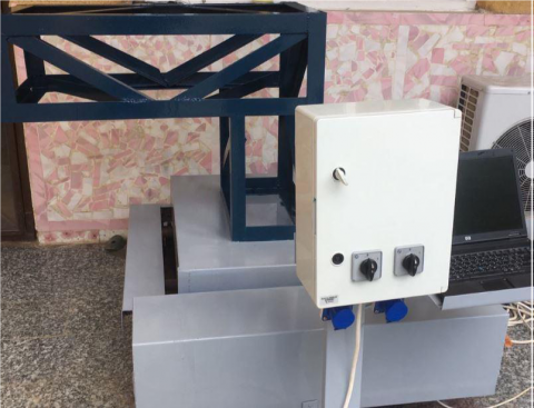
A uniaxial shake table with a rotating platform capability (2DOF; axial and rotational degrees of freedom) was planned, manufactured, and built to create a dynamic test facility servo-electrically controlled, powered by low-friction ball bushing bearings. A method has been constructed with caution to ensure a practical reproduction of input motion by the shake table method. The electrical shake table shown in Figure 1 was manufactured entirely and locally under the direct supervision of the researcher. His supervisors are uniaxial, with the ability of a rotating platform in two horizontal directions. Firstly, starting with the design and assembling the outer frame with dimensions (1m * 0.6 m), the beam responsible for the movement over lubricants ring is designed. The instrument is prepared by placing three platforms, one on top of the other. The lower platform is stationery and immovable, while the upper platforms can move in the X-axis direction, while the second can be moved towards the other Z-axis. Rings with springs were placed between the moving platforms to move and slide over each other. A movement transmission truss was manufactured using angel steel members connecting each other by welding.
Figure 1. The Shake developed by the author
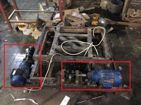
The most critical component of the device responsible for triggering table movement is the electric actuator. To fulfill the requirements for the global output characteristics of the table, two electric motors with the specifications specified were ordered. Such engines have excellent performance, such as high power, lower consumption of oil, high starting torque, low noise, low friction, stable running, simple maintenance, etc. As seen in Figure 2, motors were mounted to shake platforms.
Figure 2. Motors were fixed to the shake platforms
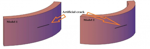
Buckingham's (π) theorem was used to demonstrate similarity linkages between systems by performing a dimension analysis [22, 23]. To make the most of the shaking table's capability, the model's geometry scale was set to 1/15.6. Four solid 3D plan concrete medium-thick arch dam structures with two distinct curvatures (each curvature comprises two models) were utilised analytically in this investigation, as shown in Figure 3. These were built from the base with the specifications and dimensions listed in Table 1. In the centre rear of the dam's body, a synthetic fracture with measurements of 20 mm in height, 20 mm in depth and 200 mm in length was created, as illustrated in Figure 3.
Figure 3. Concrete arch dam model with artificial crack
Table 1. Models dimensions
|
Compressive strength |
Density |
Poison's ratio |
Modulus of elasticity |
|
44.55 Mpa |
2400 (Kg/m3) |
0.2 |
31370 Mpa |
As the major goal of the study was to investigate dam damage induced by a severe earthquake, the nonlinear parameters of the prototype dam concrete must be replicated. The prototype concrete and model material must have the exact stress and strain relationships, even after yielding. This requirement usually is challenging to fulfil, but if the concrete can be regarded as a delicate tension material, the material loses tensile strength entirely when it arrives at its yielding point. Thus, a model material may be found since two straight lines can reflect brittle material's stress and strain relationship. To better comprehend the characteristics of the materials, common values have been chosen based on the properties and dimensions listed in Table 2.
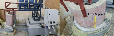
The model is installed as shown in Figure 4 with fixed the bottom by concrete. Water pressure was applied to the surface of the crack using a pressure compressor with a capacity of 10 bar, as shown in Figure 5a. Up to the full reservoirs, the water level is assumed to be 14 m. A combination of multiple loads will be applied to the dam's models, consisting of static loads (water pressure + dam's self-weight) and dynamic loads (earthquake + hydrodynamics). Linear displacement sonic transducers were used to measure the absolute response displacements in the longitudinal (horizontal) direction during the shaking table tests, as shown in Figure 5b. The LVDT fixed at a coordinate’s measures from the center of the dam as (0, -0.15,0) for LVDT in Z-direction and (-0.75, -0.15, -0.5) for LVDT in X-direction and (-0.75, -0.15, -0.5). The displacement transducer has a stroke of ±100 mm. There are various mechanical and electrical methods of measuring strain, but most stress measurements are conducted using strain gauges due to their superior measurement properties. Form (PL-60-11-3LJC-F) concrete strain gauges were used in the experimental method, with the following characteristics: wire form, with the stiffness of 119±0.5%, a gauge factor of 2.08±1%, a gauge length of 60 mm, and a gauge width of 2.5 mm with a maximum strain of 2% as seen in Figure 5c.
Table 2. Material properties
|
Model |
Outer length (m) |
Inner length (m) |
Radius (m) |
Height (m) |
Thickness (m) |
Degree of curvature |
|
1 |
1.7 |
1.5 |
1.188 |
0.9 |
0.18 |
74˚ |
|
2 |
1.7 |
1.38 |
0.65 |
0.9 |
0.18 |
124˚ |
Figure 4. Concrete arch dam model with fixed support
Figure 5. (a: applied water pressure, b: measure the displacements. c: concrete strain gauge)
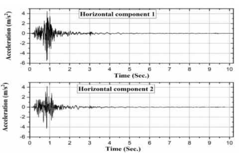
Ground Motion for the Accelerogram Portion of Mammoth Lakes-04 shown in Figure 6 was implemented to determine the output of the model structure under seismic excitation.
Figure 6. Mammoth Lakes-04 components
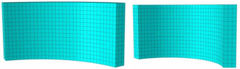
A 3D first order diminutive integration continuum element (C3D8R-Brick) is applied to model the concrete members. These elements are adaptable, allowing them to be employed in models for basic linear analysis and complex nonlinear relationships, extended deformation investigations, and plasticity. In Figure 7, a standard concrete discretisation mesh is presented.
Figure 7. Concrete members discretized using brick elements
During the significant magnitude of the Mammoth Lakes-04 1980 earthquake, model M2 showed an excellent response to the applied ground motion excitation without any damage evaluation. In contrast, there is considerable damage in M1 at the same magnitude, as shown in Figure 8. As shown in Figures 9-12, the results indicate that model 2 provides a good response compared to model 1. The horizontal component 1 (Z-Direction) records the max displacement response compared to the horizontal component 2 (X-Direction) for models M1 and M2. In contrast, the max stress recorded during the test was observed at point 3 near the dam's support. Model M1 shows severe damage through crack pattern while a slight crack propagation is observed for M2, as shown in Figure 7.
Figure 8. Deformation and crack propagation patterns
Figure 9. The response of M1 in the Z, X direction
Figure 10. The response of M2 in the Z, X direction
Figure 11. Time history graphs of the maximum principal stresses that occurred in the mid-point of M1
Figure 12. Time history graphs of the maximum principal stresses that occurred in the mid-point of M2
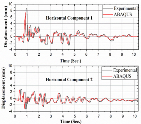
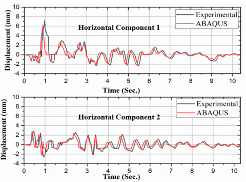
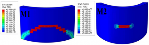
The time-history of the dam displacements, stress distribution, and crack propagation during Mammoth Lakes-04 major excitation is presented. Figures 13 to 16 provide an overview of the analytical and experimental results, indicating a satisfactory level of agreement between the two sets of results. In both practical tests and numerical analysis, model M1 indicated propagation in the crack. At the same time, there was a slight crack propagation observed in M2 during the experimental and numerical analysis under 7.7M magnitude.
Figure 13. Displacement-Time response in horizontal directions of M1
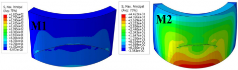
We can observe various places of stress scattered along the bodies of dams in the diagrams above. Model 1 has a maximum pressure of 60 MPa at the crack pattern, whereas model 2 has a maximum pressure of 44 MPa at the bottom quarter of the rear of the dam and some areas of the apex. Massive damage has accumulated at the rear of model1 as the earthquake duration was consecutively increased until 10.3 seconds. The maximum stresses were dispersed all over the body with 60 Mpa after a crack in the centre spread from the centre to the left and right sides. Model 2 was found to be less impacted by an increment in earthquake duration, fascinatingly. Based on what was mentioned in this paper, can reach a conclusion that in the practical reality of dams, the construction of the arch dam is due to necessities and determinants that depend on the nature of the location and the nature of the surrounding water lakes. More curved, so it will be more efficient.
Figure 14. Displacement-Time response in horizontal directions of M2
Figure 15. Stress distribution
Figure 16. Plastic deformation (STATUSXFE is unitless 0 non-cracked to 1 fully cracked)
The conclusions can be outlined in the present study as follows:
Another potential problem is that the scope of my thesis may be too broad.
1. In the future, it will be important to explore the propagation of initial vertical cracks during earthquakes.
2. Conducting an experimental and numerical analysis on the reaction of the cracked arch dams with the soil-structure interaction effect.
[1] Ghafoori, Y. (2016). Design and static analysis of arch dam using software SAP2000: master thesis (Doctoral dissertation, Univerza v Ljubljani, Fakulteta za gradbeništvo in geodezijo). http://drugg.fgg.uni-lj.si/5867/.
[2] Chen, J., Qin, L., Xu, Q., Li, J. (2020). Seismic damage indexes of a high arch dam based on the monolith. KSCE Journal of Civil Engineering, 24(7): 2063-2077. https://doi.org/10.1007/s12205-020-1202-z
[3] Liu, J., Zhang, C., Tian, S., Liu, J., Wang, H., Jia, S., You, L.Z., Zhang, M. (2013). Water conservancy projects in China: Achievements, challenges and way forward. Global Environmental Change, 23(3): 633-643. https://doi.org/10.1016/j.gloenvcha.2013.02.002
[4] Wang, H., Li, D. (2007). Experimental study of dynamic damage of an arch dam. Earthquake Engineering & Structural Dynamics, 36(3): 347-366. https://doi.org/10.1002/eqe.637
[5] Commission, F.E.R. (1999). Engineering guidelines for the evaluation of hydropower projects. Chapter 11-Arch Dams. Washington DC, 11-18. https://cmsstage.ferc.gov/industries-data/hydropower/dam-safety-and-inspections/risk-informed-decision-making-ridm-0.
[6] Fenves, G.L., Mojtahedi, S., Reimer, R.B. (1992). Nonlinear earthquake analysis of arch dam/reservoir. In Tenth World Conference on Earthquake Engineering, 8: 4595-4600.
[7] Hussein, M.N., Alfatlawi, T.J.M., Kadhim, M.J. (2021). XFEM analysis of concrete arch dam to assess deformations and propagation of artificial crack due to the combination of earthquake and uplift pressure. In Journal of Physics: Conference Series, 1773(1): 012031. http://dx.doi.org/10.1088/1742-6596/1773/1/012031
[8] Alfatlawi, T.J.M., Kadhim, M.J., Hussein, M.N. (2021). Relation between cracks behavior and curvature in cracked concrete arch dam under earthquake. Materials Today: Proceedings, 2021. https://doi.org/10.1016/j.matpr.2021.02.248
[9] Tan, H., Chopra, A.K. (1995). Earthquake analysis of arch dams including dam‐water‐foundation rock interaction. Earthquake Engineering & Structural Dynamics, 24(11): 1453-1474. https://doi.org/10.1002/eqe.4290241104
[10] Melenk, J.M., Babuška, I. (1996). The partition of unity finite element method: basic theory and applications. Computer Methods in Applied Mechanics and Engineering, 139(1-4): 289-314. https://doi.org/10.1016/S0045-7825(96)01087-0
[11] Okodi, A., Li, Y., Cheng, R., Kainat, M., Yoosef-Ghodsi, N., Adeeb, S. (2020). Crack propagation and burst pressure of pipeline with restrained and unrestrained concentric dent-crack defects using extended finite element method. Applied sciences, 10(21): 7554. https://doi.org/10.3390/app10217554
[12] Moës, N., Dolbow, J., Belytschko, T. (1999). A finite element method for crack growth without remeshing. International Journal for Numerical Methods in Engineering, 46(1): 131-150. https://doi.org/10.1002/(SICI)1097-0207(19990910)46:1<131::AID-NME726>3.0.CO;2-J
[13] Simulia, D.S. (2011). Abaqus 6.11 theory manual. Providence, RI, USA: DS SIMULIA Corp. http://130.149.89.49:2080/v6.11/pdf_books/THEORY.pdf.
[14] Zhang, S., Wang, G., Yu, X. (2013). Seismic cracking analysis of concrete gravity dams with initial cracks using the extended finite element method. Engineering Structures, 56: 528-543. https://doi.org/10.1016/j.engstruct.2013.05.037
[15] Lin, P., Wei, P., Wang, W., Huang, H. (2018). Cracking risk and overall stability analysis of Xulong high arch dam: A case study. Applied Sciences, 8(12): 2555. https://doi.org/10.3390/app8122555
[16] Paggi, M., Ferro, G. (2010). Nonlinear interface crack propagation in concrete gravity dams under seismic loading. http://eprints.imtlucca.it/id/eprint/2081.
[17] Lombarkia, H., Kadid, A., Youb, Y. (2018). Nonlinear dynamic analysis of arch dams considering contraction joints. Asian Journal of Civil Engineering, 19(3): 249-262. https://doi.org/10.1007/s42107-018-0021-8
[18] Kadhim, M., Alfatlawi, T., Hussein, M. (2021). Experimental and nonlinear analysis of cracking in concrete arch dams due to seismic uplift pressure variations. International Journal of Engineering, 34(5): 1156-1166. https://dx.doi.org/10.5829/ije.2021.34.05b.09
[19] Harris, D.W., Snorteland, N., Dolen, T., Travers, F. (2000). Shaking table 2‐D models of a concrete gravity dam. Earthquake Engineering & Structural Dynamics, 29(6): 769-787. https://doi.org/10.1002/(SICI)1096-9845(200006)29:6<769::AID-EQE925>3.0.CO;2-7
[20] Wang, H., Li, D. (2006). Experimental study of seismic overloading of large arch dam. Earthquake Engineering & Structural Dynamics, 35(2): 199-216. https://doi.org/10.1002/eqe.517
[21] Center, P. (2013). PEER ground motion database. Pacific Earthquake Engineering Research Center, University of California, Berkeley, CA. https://ngawest2.berkeley.edu/.
[22] Harris, H.G., Sabnis, G. (1999). Structural Modeling and Experimental Techniques. CRC Press.
[23] Shokrieh, M.M., Askari, A. (2013). Similitude study of impacted composite laminates under buckling loading. Journal of Engineering Mechanics, 139(10): 1334-1340. https://doi.org/10.1061/(ASCE)EM.1943-7889.0000560