Fei Zhang* | Guangchuan Fu
© 2020 IIETA. This article is published by IIETA and is licensed under the CC BY 4.0 license (http://creativecommons.org/licenses/by/4.0/).
OPEN ACCESS
This paper attempts to improve the evaluation accuracy of additional mass method in the compaction quality of earth-soil composite foundation. For this purpose, an earth-soil composite foundation was formulated, and tested by additional mass method. Through the test, the authors analyzed the correlations between technical parameters (e.g. additional mass, and the number of loading steps) and the main frequency, stiffness, and mass of vibration of the earth-rock composite foundation. Besides, the settings of technical parameters were optimized for the application of additional mass method. Finally, the accuracy of additional mass method was verified through engineering application. The results show that: (1) With the growth in additional mass, the resonant main frequency of the resonator, which consists of the foundation and the additional mass, exhibited a declining trend. For a single measuring point, the resonant main frequency of the resonator showed a slight linear decrease. (2) A suitable additional mass helps to improve the test accuracy of the additional mass method for the stiffness and mass of vibration of the foundation. (3) With the growing number of loading steps, the stiffness and mass of vibration of earth-soil composite foundation both decreased. In actual application, the number of loading steps should be properly increased. (4) Additional mass method has a high evaluation accuracy of compaction quality of earth-soil composite foundation. The research results shed new light on the evaluation of compaction quality of earth-rock composite foundation.
additional mass method, technical parameters, earth-rock composite foundation, model test, engineering application
The earth-rock composite foundation has been widely used in foundation projects (e.g. earth-rock dam foundation, and land filling in port area) in mountainous and hilly regions, thanks to its excellence in engineering and economy. Compaction quality is a key indicator of the construction quality of earth-rock composite foundation. This indicator must be tested and evaluated in an accurate manner [1]. Traditionally, compaction quality is tested by sand filling method and water filling method [2, 3]. The traditional methods are time-consuming and labor-intensive, and apply only to shallow earth foundations filled by materials of small particle size.
Recently, novel theories and methods for rapid test of compaction quality have emerged, namely, wave velocity testing, and wave-electric field coupling imaging [4-6]. These emerging methods have been applied to engineering. But these methods also face certain limitations: there are interferences in the selection and statistics of structural control parameters; the testing is greatly affected by field test equipment and signal acquisition. Therefore, it is necessary to develop a new method to test the compaction quality of earth-rock composite foundation.
In recent years, the additional mass method has been widely adopted by hydraulic engineers to determine the compaction quality of rockfills. Li et al. [7] were the first to measure rockfill density by additional mass method. Since then, many scholars have explored the feasibility of the method, which is fast, in-situ and non-destructive. Wang et al. [8], Song et al. [9], Cai and Zhang [10], and Tan et al. [11] conducted field tests based on additional mass method, evaluated the application effects of the method, and proved that the method is reasonable and reliable. Chen et al. [12] relied on additional mass method to detect the compactness of coarse-grained soil, which widens the applicable scope of this method. Li and Guo [13], Xue et al. [14], and Li et al. [15] applied additional mass method to density inversion problem. Based on additional mass method, Zhang et al. [16-18] analyzed the impacts of additional mass coefficient, main frequency determination method, offset distance, and vibration source height, carried out finite-element simulation of rockfill density based on these factors, and put forward the reference values of each test parameter. The above studies demonstrate that additional mass method is mature and reliable enough for rockfill density test. Hence, it is possible to introduce additional mass method to the compaction quality test of earth-rock composite foundation.
However, the existing studies fail to consider two issues: (1) Earth-rock composite foundation features large gradation changes and extremely uneven water content. The foundation differs sharply from the rockfill in physical-mechanical properties. Nonetheless, there is no report that applies additional mass method to test the compaction quality of earth-rock composite foundation. (2) In the theory of additional mass method, the additional mass and the number of loading steps directly bear on the density inversion and compaction quality evaluation of the foundation. But no standard is available for technical parameters in actual tests.
This paper aims to improve the rationality and accuracy of additional mass method in the compaction quality evaluation of earth-rock composite foundation. For this purpose, an earth-rock composite foundation was modelled, and tested by additional mass method. Through the test, the authors analyzed the correlations between technical parameters (e.g. additional mass, and the number of loading steps) and the main frequency, stiffness, and mass of vibration of the earth-rock composite foundation. Finally, the accuracy of additional mass method was verified through engineering application. The research results lay the theoretical and practical bases for rationalizing technical parameters, optimizing the test plan, and measuring the exact compaction quality of earth-rock composite foundation.
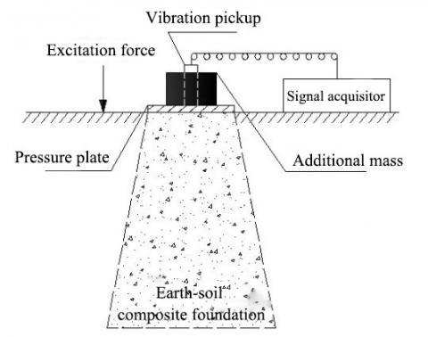
Additional mass method is an in-situ test strategy for density measurement. By this method, an earth-soil composite foundation under the excitation force is modelled as a linear elastic vibrating mass. The original foundation and the vibration model are illustrated in Figure 1 below.
(a) Original foundation (b) Vibration model
Figure 1. Earth-soil composite foundation and its vibration model
The vibration model can be dynamically described as [19]:
$m Z^{\prime \prime}+K Z=0$ (1)
$K=\omega^{2} m$ (2)
where, m, Z", K, and Z are the mass, acceleration, dynamic stiffness, and displacement of the vibration system, respectively; ω is the circular frequency of particle vibration.
During the test, an additional mass is placed on the surface of the foundation. Then, the total mass of the vibration system equals the mass of vibration m0 of the earth-soil composite foundation plus the additional mass Δm. Based on formulas (1) and (2), we have:
$\left(\Delta m+m_{0}\right) Z^{\prime \prime}+K Z=0$ (3)
$K=\omega^{2}\left(\Delta m+m_{0}\right)$ (4)
Assuming that the foundation is a linear mass, the total response of the foundation to multiple mass loads equals the sum of the responses to single mass loads. The summation should be conducted in the principle of superposition [20].
Multiple additional masses are applied to the foundation with a step mass of Δm. After each mass is applied, the circular frequency of particle vibration ω is measured. Then, the ω-2-Δm curve is plotted, whose inverse slope is stiffness K. The intercept on the Δm axis is the mass of vibration m0. On this basis, the foundation density can be derived from stiffness and mass of vibration, according to the theory of density inversion [20].
3.1 Model construction
The foundation model is 4.5 m long, 3 m wide and 0.8 m tall. Brick walls were built on three sides. The cross-section of the model is a right-angled trapezoid, with a 3 m long top edge and a 4.5 m long bottom edge. The gradient of the slope is 1:1.875. The model design is illustrated in Figure 2 below.
To fill the foundation model, earth-rock materials were obtained by the weathering and crushing of typical strongly weathered mudstone in Chongqing, China. By the particle size d=5 mm, the earth-rock materials were divided into earth (fine aggregate) and rock (coarse aggregate). After screening by particle size, the earth-rock ratio was measured as 1:1 in mass. Through indoor compaction test, the optimal water content and maximum dry density of the mixture were obtained as 10.6% and 1.95 g·cm-3, respectively.
Figure 2. The earth-soil composite foundation model
Figure 3. Layered compaction of the foundation
Figure 4. The final foundation model
The foundation model was filled in three layers. The first layer is 30 cm thick, and the second and third layers are 25 cm thick. After each layer was filled up, the fillers were compacted with a vibratory tamper that moves at a constant speed along alternating paths in the vertical and horizontal directions. The compaction was not terminated until the compacted surface was flattened, with no obvious cracks (Figure 3). To control the filling quality, two points were randomly selected for pit measurement, after each layer was fully compacted. Figure 4 shows the final foundation model.
3.2 Test system
During our test, the vibration signals were collected by a DZQ high-resolution seismograph (CGE (Chongqing) Geological Instrument Co., Ltd., China). The pressure plate is a circular steel plate with a diameter of 50cm and a thickness of 20 mm. Several cast iron weights, and a 28 Hz speed type vibration pickup with no tail cone were also adopted for our test. The test system is illustrated in Figure 5.
Figure 5. The test system
3.3 Test method and steps
Step 1. The test site was levelled. A 2cm-thick layer of fine sands was laid on the surface of the measuring point. Then, the pressure plate was placed directly above that point, and in close contact with the foundation surface.
Step 2. The coupling agent was applied on the bottom of the vibration pickup, which was then connected to the signal acquisitor with wires. According to the test plate, additional masses were placed evenly and symmetrically on the pressure plate (Figure 6).
Figure 6. Placement of additional masses
Step 3. The instruments were turned on to configure the test parameters.
Step 4. The vibration source was activated at a certain distance from the pressure plate, and the signals were collected under the excitation force. In this way, the time-domain signal curve of the vibration system was obtained, which covers additional mass, pressure plate, and the mass of vibration of earth-soil composite foundation.
Step 5. The time-domain signal curve was converted into a frequency-domain signal curve through fast Fourier transform (FFT). To facilitate observation and ensure repeatability (consistency), three excitations were carried out for each level of additional mass, creating three frequency-domain signal curves. If the resonant main frequency of the three tests are highly repeatable, then the peak frequency of the spectrum curve is the resonant main frequency of the foundation and the additional mass(es).
Step 6. Steps 4 and 5 were repeated to complete the testing of one measuring point under different layers of additional masses.
Step 7. Step 6 was repeated until all measuring points had been tested.
4.1 Influence of additional mass on resonant main frequency
Through five-step loading, the time-domain signal curves of each measuring point under the additional masses of 300kg and 480kg were subjected to the FFT. In this way, the authors obtained the resonant main frequencies of the foundation at the measuring points under the two additional masses in each step (Figure 7).
(a) Δm=300kg
(b) Δm=480kg
Figure 7. Resonant main frequencies of the foundation
As shown in Figure 7, when the additional mass remained constant (i.e. the foundation was loaded with the same additional mass), the frequency response of the resonator, which consists of the foundation and the additional mass, varied with the masses of vibration of the foundation. With the growth in additional mass, the resonant main frequency of the resonator exhibited a declining trend, which agrees with the general dynamics of the structure.
For a single measuring point, the resonant main frequency of the resonator also decreased gradually, in the multi-step loading of additional masses. But the weak linear decrease differs from the nonlinear relationship between main frequency and additional mass, as specified in the theory of additional mass method. The difference stems from two factors: First, some nonlinear points are missing, due to the limited number of loading steps. Second, the extraction of main frequencies is not always stable, under the effects of the coupling between the foundation and additional mass and the test errors.
4.2 Influence of additional mass on stiffness and mass of vibration
Based on main frequencies, the stiffness and mass of vibration of the foundation were derived from the inverse slope of ω-2-Δm curve and the intersection between the curve and x-axis. Figures 8 and 9 display the stiffness and mass of vibration of the foundation point under the additional masses of 300 kg and 480 kg in five-step loading, respectively.
Figure 8. Stiffness of the foundation
Figure 9. Mass of vibration of the foundation
As shown in Figures 8-9, as the additional mass increased from 300kg to 480kg, the stiffness and mass of vibration at the measuring points of the foundation might increase or decrease, and the increment/decrement varied from place to place.
Under the load of 300kg, the stiffness and mass of vibration of the foundation fell within 46.5-64.1MN/m and 312-424kg, respectively. Under the load of 480kg, the stiffness and mass of vibration of the foundation fell within 49.3-63.7MN/m and 343-387kg, respectively. The ranges of the two technical parameters both narrowed down.
In fact, the parameter values of the same foundation model should remain the same or cluster together, under the premise of that the compaction is uniform and the test environment is constant. In other words, the stiffness and mass of vibration should fall in small intervals. Therefore, a suitable additional mass helps to improve the test accuracy of the stiffness and mass of vibration of the foundation.
In addition, the stiffness and mass of vibration measured at the same point both increased or both decreased, under the load of different additional masses, i.e. the two technical parameters were consistent in the change direction.
4.3 Influence of the number of loading steps on stiffness and mass of vibration
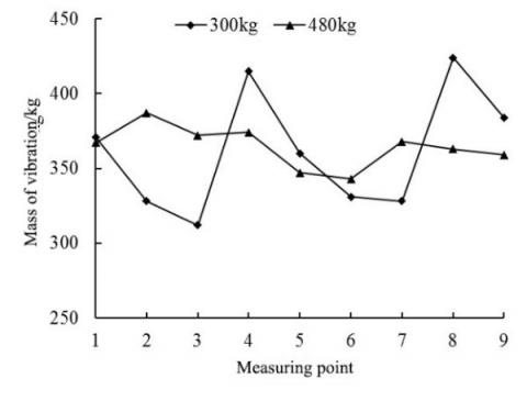
The next step is to disclose how the number of loading steps affects stiffness and mass of vibration. Fixing the additional mass to 480kg, the number of loading steps was increased from 5 to 8: 100 kg, 160 kg, 200 kg, 240 kg, 300 kg, 360 kg, 400 kg, and 480 kg. Figures 10 and 11 compare 5-step loading and 8-step loading in terms of stiffness and mass of vibration, respectively.
Figure 10. Stiffness of the foundation
Figure 11. Mass of vibration of the foundation
As shown in Figures 10 and 11, with the growing number of loading steps, the stiffness and mass of vibration decreased in different degrees at all measuring points, except for points 6 and 8. The stiffness decrement was 6.4% at the maximum, and 1.6% at the minimum; The mass of vibration decrement was 11.4% at the maximum, and 1.4% at the minimum. Considering test errors and outliers, it can be concluded that the growing number of loading steps reduces the technical parameters of the foundation.
In essence, the growing number of loading steps is equivalent to the growth in the number of fitting points for the linear regression of ω-2-Δm curve. To a certain extent, this pushes up the fitting accuracy, and lowers the relative errors of stiffness and mass of vibration. Meanwhile, the growing number of loading steps reduces the difference between adjacent loading steps in vibration frequency. During signal processing (especially the FFT), the reduced difference might cause picket fence effect, threatening the quality of spectrum analysis.
5.1 Project overview
Longzhouwan Block B Municipal Roads Project (Phase II) aims to meet the medium and long-distance travel demands in Banan District, Chongqing, China, facilitating the travelling of residents and businesses in the area. There are eight roads in the project, linking up Yunan Avenue with the roads in Phase I of the project.
Our test was carried out on Yizhong Road in Phase II of the project. Yizhong Road is a trunk road in Chongqing, with a total length of 3,603.25 m, standard cross-section width of 44m, and vehicle speed of 50 km/h.
In the test section, the landform is characterized by shallow hills, slopes, and grooves formed through tectonic denudation. The geological conditions along the road are stable, and suitable for highway construction.
The fill subgrade of Yizhong Road is filled with sufficient materials, including cohesive sand, shale, sandstone, limestone, granite, etc. The subgrade is a typical earth-soil composite foundation.
5.2 Field test and results
The field test is split into two parts: calibration test and target test. Nine measuring points were randomly selected for the calibration test, and five were randomly selected for the target test. According to the additional mass method and actual needs of field test, the following instruments were utilized: a high-resolution seismograph, a 400kg additional mass, a 50cm-diameter iron pressure plate, a 20kg weight drop vibration exciter, and a 40Hz speed type vibration pickup. The test parameters were configured as follows: excitation offset, 40cm; drop distance, 40cm.
Figure 12. The field test
Table 1. Results of calibration test
|
Calibration points |
Stiffness/MN·m-1 |
Mass of vibration /kg |
Measured dry density/g·cm-3 |
|
1 |
75.1 |
364 |
2.074 |
|
2 |
68.3 |
314 |
2.030 |
|
3 |
71.1 |
343 |
2.065 |
|
4 |
83.6 |
459 |
2.089 |
|
5 |
70.2 |
341 |
2.037 |
|
6 |
70.3 |
336 |
2.059 |
|
7 |
66.7 |
307 |
2.058 |
|
8 |
77.8 |
368 |
2.072 |
|
9 |
80.5 |
412 |
2.099 |
The field test (Figure 12) was carried out in three steps:
Step 1. Obtain the stiffness and mass of vibration (Table 1) of the subgrade by testing the calibration points with additional mass method.
Step 2. Determine the calibration relationship between stiffness and the dry density obtained through pit measurement on the subgrade.
Step 3. Substitute the stiffness values at target points to the above relationship to yield the dry density of the subgrade.
Based on Table 1, density inversion was performed by stiffness correlation method [22]. In this way, the authors obtained the linear regression relationship between normalized stiffness and dry density of subgrade. Then, the dry density ρd of the subgrade can be expressed as:
$\rho_{d}=0.0008 \frac{K}{r}+1.8296$ (5)
where, K is the stiffness of the subgrade; r is the radius of the pressure plate.
Next, the five target points were tested by additional mass method. The stiffness and mass of vibration at each target point were obtained, and used to further inverse the dry density by formula (5). The results of the target test are listed in Table 2.
Table 2. Results of target test
|
Target points |
Stiffness/MN·m-1 |
Mass of vibration /kg |
Inversed dry density/g·cm-3 |
|
1 |
74.5 |
385 |
2.068 |
|
2 |
66.2 |
320 |
2.041 |
|
3 |
78.7 |
352 |
2.081 |
|
4 |
73.8 |
368 |
2.066 |
|
5 |
64.1 |
313 |
2.035 |
Based on the results of Table 2, the compaction quality was calculated by the compactness calculation formula. The calculated results are recorded in Table 3, in which the maximum dry density was 2.19 g·cm-3. It can be seen from Table 3 that the compactness of the subgrade evaluated by the additional mass method are consistent with that of pit measurement. Therefore, the additional mass method can accurately evaluate the compaction quality of earth-soil composite foundation.
Table 3. Compactness at target points
|
Target points |
Calculated compactness/% |
Measured compactness/% |
|
1 |
94.4 |
94.7 |
|
2 |
93.2 |
94.4 |
|
3 |
95.0 |
95.7 |
|
4 |
94.3 |
94.1 |
|
5 |
92.9 |
93.8 |
This paper carries out model test and engineering application of additional mass method in earth-soil composite foundation. The main conclusions are as follows:
(1) With the growth in additional mass, the resonant main frequency of the resonator, which consists of the foundation and the additional mass, exhibited a declining trend, which agrees with the general dynamics of the structure. For a single measuring point, the resonant main frequency of the resonator showed a slight linear decrease.
(2) The stiffness and mass of vibration at the same point of the earth-soil composite foundation both increased or both decreased, with the growth of additional mass. The ranges of the two technical parameters both narrowed down. Therefore, a suitable additional mass helps to improve the test accuracy of the additional mass method for the stiffness and mass of vibration of the foundation.
(3) With the growing number of loading steps, the stiffness and mass of vibration of earth-soil composite foundation both decreased. The growth in the number of fitting points lowers the test errors of stiffness and mass of vibration. In actual application, the number of loading steps should be properly increased. Besides, attention should be paid to prevent the picket fence effect in spectrum analysis.
(4) Engineering application confirms that additional mass method has a high evaluation accuracy of compaction quality of earth-soil composite foundation.
The authors gratefully acknowledge the financial supports from Jiangxi Youth Science Fund Project (Grant No. 20171BAB216042).
[1] Chai, H.J., Chen, L.Y., Kong, X.C., Dong, Y. (2004). Overview of soil-stone high embankment construction study. Rock and Soil Mechanics, 25(6): 1005-1010. https://doi.org/10.3969/j.issn.1000-7598.2004.06.037
[2] Cao, W.G., Luo, H., Zhang, J.S., Wang, H.Y., Zhang, C. (2013). Determination method for subgrade compactness with static penetration based on Duncan-Chang constitutive model. China Journal of Highway and Transport, 26(5): 1-8. https://doi.org/10.3969/j.issn.1001-7372.2013.05.001
[3] Deng, X.W., Cai, Y.C., Guo, C.C. (2007). Experience of compactness of express way subgrade detected using sand cone method. Subgrade Engineering, 20(6): 142-143. https://doi.org/10.3969/j.issn.1003-8825.2007.06.070
[4] Zhao, M.J. (2007). Theoretical model for calculating compactness of soil-stone mixture foundation according to wave propagation velocity. Journal of Hydraulic Engineering, 38(5): 618-623. https://doi.org/10.3321/j.issn:0559-9350.2007.05.017
[5] Zhao, M.J., He, Y., Rong, Y., Huang, W.D. (2011). Experiment on electrical resistivity imaging diagnosis of fill subgrade compaction quality. China Journal of Highway and Transport, 24(3): 16-21. http://zgglxb.chd.edu.cn/CN/Y2011/V24/I3/16
[6] Wang, K., Zhao, M.J., Sun, X. (2017). Wave-electric field coupling imaging diagnostic method for filled subgrade. Journal of Mountain Science, 14(2): 382-389. https://doi.org/10.1007/s11629-016-4023-2
[7] Li, P.W., Len, Y.B., Yuan, J.H. (1999). Additional mass method for density determination of rockfill. Journal of Geophysics, 42(3): 422-427. https://doi.org/10.3321/j.issn:0001-5733.1999.03.016
[8] Wang, G.Z., Wang, Y.M., Geng, Y.P., Zhao, F. (2002). Application of additional quality method in stone filling engineering, Highway, (2): 28-31. https://doi.org/10.3969/j.issn.0451-0712.2002.02.009
[9] Song, X.H., Xiao, B.X., Gu, H.M., Zhang, X.Q., Deng, S.K., Xu, S.F. (2004). Application of method of additive mass to density measurement of rock-fill object in Shuibuya water control project. Coal Geology & Exploration, 32(3): 40-42. https://doi.org/10.3969/j.issn.1001-1986.2004.03.014
[10] Cai, J.X., Zhang, Z.J. (2008). Analysis and evaluation on application effect of density measurement of rock fill object by additive mass method. Journal of Yangtze River Scientific Research Institute, 25(5): 186-190. https://doi.org/10.3969/j.issn.1001-5485.2008.05.043
[11] Tan, F.Y., Jiang, Z.Q., Li, Z.Q., Yan, H.H. (2010). Application of additive mass method to testing compacted density of filling material in Kunming new airport. Rock and Soil Mechanics, 31(7): 2214-2218. https://doi.org/10.3969/j.issn.1000-7598.2010.07.032
[12] Chen, T., Guo, Y.C., Xie, C.Q., Jin, J.W. (2008). Application of additive mass method in the compaction quality measurement of over coarse-grained soils. 2008 International Conference on Information Management, Innovation Management and Industrial Engineering, Taipei, Taiwan, pp. 52-55. https://doi.org/10.1109/ICIII.2008.73
[13] Li, P.W., Guo, Y.S. (2009). Technology of in-situ intensity test for rock-earth filling. Technical Supervision in Water Resources, (1): 39-41. https://doi.org/10.3969/j.issn.1008-1305.2009.01.013
[14] Xue, Y.F., Li, P.W., Cui, L., Li, X.L. (2010). Measurement of rockfill density by stiffness correlation method. Journal of Geotechnical Engineering, 32(6): 987-990.
[15] Li, X.L., Pei, S.Y., Yang, H.Y. (2010). Research on the volume correlated method in the inversion of additive mass method. Journal of North China Institute of Water Conservancy and Hydroelectric Power, 31(5): 65-67. https://doi.org/10.3969/j.issn.1002-5634.2010.05.018
[16] Zhang, Z., Liu, X.F., Cai, J.X., Fan, Y.H., Ma, S.M. (2013). A experimental study on density measurement of rock fill object by additive mass method. Progress in Geophysics, 28(1): 498-506. https://doi.org/10.6038/pg20130157
[17] Zhang, Z., Li, X., Cai, J.X., Fan, Y.H., Ma, S.M., Xie, H. (2014). Numerical simulation of additional mass method for the determination of rockfill density. Progress in Geophysics, 29(3): 1472-1483. http://dx.doi.org/10.6038/pg20140366
[18] Zhang, Z., Fan, Y.H., Cai, J.X., Li, X., Ma, S.M., Liu, C. (2015). Theoretical analysis on density measurement of rockfill body by additive mass method. Chinese Journal of Geophysics, 58(1): 257-266. http://dx.doi.org/10.6038/cjg20150123
[19] Chopra, A.K. (2001). Dynamics of Structures: Theory and Applications to Earthquake Engineering, Second Edition. New Jersey: Prentice-Hall.
[20] Li, P.W., Hu, W.H., Zhang, J.Q. (2014). Additional mass method: In situ rapid detection technology of rockfill density. Zhengzhou: Yellow River Water Conservancy Press.