Synthesis and Characterization of Co2O3 Thin Films by Pulsed Laser Deposition Method and Investigation Zscan and Gas Sensing Applications

Manar Lo.Dayekh*![]() | Amin Ghadi
| Amin Ghadi![]() | Saleem A. Hussain
| Saleem A. Hussain![]()
© 2024 The authors. This article is published by IIETA and is licensed under the CC BY 4.0 license (http://creativecommons.org/licenses/by/4.0/).
OPEN ACCESS
In this study, cobalt oxide Nano films were fabricated by pulsed laser deposition method on glass substrates. The structures of the cobalt oxide thin films were investigated FE-SEM images showed spherical nanoparticles with a diameter of (10-28 nm) and the particles appeared in the case of clustered pushes, and the absorption spectra showed a strong peak in the ultraviolet region at 300 nm. The result of the third-order nonlinear optical properties of cobalt oxide films also showed saturated absorption and nonlinear concentration. Thus, the cobalt oxide Nano films possess good features in nonlinear applications. The electrical features of the cobalt oxide films improved highly. The Nano films also showed NO2 sensing activity (29%, 25%, 24%) at temperatures (200, 250, 300℃) respectively. The result showed that cobalt oxide Nano films can be used in a wide range of applications.
Co2O3 thin films, pulse laser deposition, optical properties, gas sensor
Intense laser pulses are used in the thin-film deposition technique known as pulsed laser deposition (PLD) to vaporize the target material. Ablated particles leave the target and condense on the substrate. A vacuum chamber is used for the deposition process to reduce particle dispersion [1]. The plasma produced through a laser is transient and highly dependent on the incident laser energy (laser wavelength, ambient gas composition, and pressure; laser pulsed energy/spot area. In this context, a thin film is defined as a layer of material with a thickness of one nanometer to one micrometer. Numerous industries use nanoparticles, which are also attributed with improvements in data storage, cutting-edge optical coatings, and energy production. Thin layers are frequently used to improve the properties of a material's surface. To enhance a surface's electrical behavior, transmission, absorption, reflection, hardness, resistance to abrasion, corrosion, and penetration, a thin coating can be applied. Furthermore, thin-film technologies are the foundation of nanotechnology [2]. PLD is the best method for complex deposition compositions because it gives the user more control over the deposition stoichiometry. Additionally, it has made a significant contribution to the study of materials, spanning numerous complex material applications [3, 4]. Since then, lasers have found extensive use in numerous technical disciplines. The process of ablating the target substance is difficult. The laser pulse could, however, go beyond the material's surface to a certain depth. This dimension, which is typically in the 10 nm range, is determined by the laser's wavelength and the target material's refractive index. The solid electrical field is powerful enough to remove electrons from the majority of the penetrated volume within ten picoseconds for a nanosecond laser pulse [5]. PLD is an easy procedure that is carried quite frequently. The serial growth of the generated plasma plume is one of its many remarkable features, along with its ability to ablate a target material using a laser pulse delivered to a substrate. The PLD process is incredibly complex despite the design's simplicity. The previous steps of the process frequently cross over, are interconnected, and contain a variety of deposition parameters that can be altered and have a direct impact on the properties of the formed thin films [6, 7]. These parameters could be the composition of the target, the laser's wavelength, the laser's pulse width, the spot size, the fluence, the pressure, the separation between the target and the substrate, and the temperature of the substrate [8].
The sample is thought to be transported along the Z-axis in the Z-scan approach., beyond the Gaussian beam's focus point. As the sample travels, the way the light from the laser interacts with the medium changes as well. The spatial relationship (z) of the sample with relation to z=0, the focus point is responsible for the variance in intensities [9]. The standard protocol calls for placing the sample exactly at the lens's focus point and then moving it at a distance denoted by $z_{\circ}$, where z is the Rayleigh length, progressively down the z-axis [10].
$\mathrm{Z}_{\circ}=\frac{\omega_{\circ}^2}{\lambda} \pi$ (1)
where, $\omega_{\circ}$: the laser beam's radius, but λ: symbolised the wavelength.
Z-scan may be used in two ways: with closed and gaps in the open. Nonlinear refraction is measured using the tight aperture Z-scan, while nonlinear absorption is measured using the wide aperture Z-scan [10].
According to Sheik-Bahae et al. [10], there is a direct correlation between the temperature change, ΔT and the nonlinear phase shift, Δ. It is frequently noted that the difference between the normalized transmittance's maximum and minimum magnitudes functions as a trustworthy indicator of nonlinearity.
$\Delta T_{p-v}=0.406\left|\Delta \Phi_{\circ}\right|$ (2)
where, the constant amount is 0.406. Additionally
$\Delta \Phi_{\circ}=k n_2 I_o L_{e f f}$ (3)
$\Delta \Phi_{\circ}$: nonlinear phase shift, in which I stood for the initial laser beam intensity at focus z=0 and k for the wave number [11].
$I_0=P / 2 \pi \omega_{\circ}^2$ (4)
while laser beams radius is $\omega_0$, and P is its strength.
$\mathrm{L}_{e f f}=\left(1-\exp ^{(-\alpha \mathrm{t})} / \alpha\right)$ (5)
where, Leff is the effective thickness of the sample [12].
The nonlinear refraction index, denoted as n2, is demonstrated via:
$\mathrm{n}_2=\Delta \Phi / \mathrm{kI}_{\circ} \mathrm{L}_{\text {eff }}$ (6)
The following expression describes the relationship between the intensity of a laser beam ($\mathrm{I}_{\circ}$) and change in the nonlinear refractive index (Δn):
$\Delta \mathrm{n}=\mathrm{n}_2 \mathrm{I}_{\mathrm{o}}$ (7)
Using the following formula, the nonlinear absorption coefficient may be calculated from the open aperture curve [13]:
$\beta=\frac{2 \sqrt{2}}{I_0 L_{e f f}} \Delta T$ (8)
When an open aperture is used, the variable ∆T indicates the happening of a single peak or single the Z-scan's valley curve. The nonlinear optical susceptibility of the third order χ (3) may be explained by Eqs. (9) and (10). These correlations demonstrate that the nonlinear refraction index is represented by the real component of χ (3), and the nonlinear absorption coefficient by the virtual component [14].
$\operatorname{Re}[\chi ^{(3)}](\mathrm{esu})=10^{-4} \frac{\epsilon_{\circ} c^2 n_{\circ}^2 n_2}{\pi}\left(\mathrm{cm}^2 / \mathrm{W}\right)$ (9)
$\operatorname{Im}[\chi ^{(3)}](\mathrm{esu})=10^{-2} \frac{\epsilon_{\circ} c^2 n_{\circ}^2 \lambda \beta}{4 \pi^2}\left(\mathrm{~cm}^2 / \mathrm{W}\right)$ (10)
The relation can be calculated the absolute value of third order nonlinear optical susceptibility, denoted as |χ (3)|, by used illustrated equation.
$\left|\chi ^{(3)}\right|=\left[\operatorname{Re}\left(\chi ^{(3)}\right)+\operatorname{Im}\left(\chi ^{(3)}\right)\right]^{1 / 2}$ (11)
Metal oxides are regarded as one of the best materials for use in creating the gas sensor. They have typically proved to be resistant to high temperatures, exhibit optical transparency in visible wavelengths, and have a large gap [15, 16].
The key to chemical sensing applications is the reactive nature of metal oxides. When these materials are exposed to oxidizing gases, such as O2 gas and NO2 gas, they tend to form oxygen ions (O-) or (O2-), which are electrically active. For the oxygen ion to stabilize, it must be spread in the vacant levels that were formed as a result of crystalline defects within the composition of the metal oxide, as in the equations below [16].
$\mathrm{O}_2+e^{-} \rightarrow \mathrm{O}_2^{-}$ (12)
$\mathrm{O}_2^{-}+e^{-} \rightarrow 2 \mathrm{O}^{-}$ (13)
Chemical sensors therefore rely on changes in resistance because semiconductors of the type (n-type) change resistance in the presence of gas from the highest to the lowest value, whereas semiconductors of the type (p-type) change resistance in the opposite direction (from the lowest to the highest value). In this work, the structural, linear, and nonlinear optical characteristics of cobalt nanoparticles produced using the pulsed Nd-Yag laser deposition technique were investigated. The outcomes are promising and intriguing, and they may be utilised to design and gain certification for the production of optical solar cells, optical sensors, and other optical devices [16].
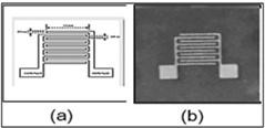
In order to produce thin films of Co2O3 (100-2000 mJ), it is necessary to use a 1064 nm wavelength, 1500 mJ energy, and vacuum pressure pulsed Nd-Yag laser of 8×10⁻² mbr, and 6 Hz in frequency. The cobalt oxide (Co2O3) target, which was positioned on the target holder in the shape of a rotating disc, was compressed into tablets (Pellet) with a 10-ton compressive force via a hydraulic press. In front of the target, a foundation made of glass that had been carefully constructed for this purpose was set on the slide holder. The target is 4 cm distance the glass substrate. It is necessary to use the laser beam at a 45°. The vacuum chamber shuts and the rotary pump valve opens, starting the pump when the required pressure is attained. The sample is exposed to laser pulses to be able to form a column of plasma containing material particles that will be deposited. Electrodes were also placed using masks, and their size was related to the Co2O3 thin film's in order to assess the gas sensor, measure. The electrode material used during the deposition process was 99.9% pure aluminum. Figure 1 illustrates a steel mask was used to deposit the electrodes used in the gas sensor test. The deposition procedure's evaporation system had a pressure of 8×10⁻² mbr.
Figure 1. The electrodes masks used in the gas sensor measurements: (a) Schematic of aluminum electrode deposition mask for gas sensor measurement; and (b) The sample after deposition of aluminum electrodes to measure the gas sensor
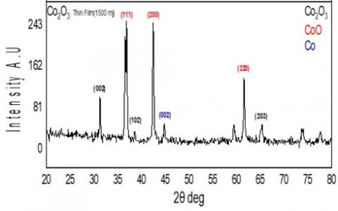
3.1 Result of XRD
Through Figure 2, which represents the X-ray diffraction pattern of cobalt oxide thin film (Co2O3), a number of intensity and peaks were observed in the s pectrum of cobalt oxide thin films, which belongs to a hexagonal crystal structure by comparing it with the results of the standard card (Co2O3 – Card Number (00-005-0727)). The presence of clear peaks levels (002) (102) (203) at angles (31.2746º), (38.4964º) and (67.307º) respectively and also note a number of peaks representing Co-Card Number (00-005-0727)) and cobalt oxides and (CoO -Card Number (00-048-1719) and that the systems Apparent crystal lines, angles and Miller's coefficients are indicative in this figure.
The influence of laser oxidation is a necessary result of the effect of the laser on metals and this effect occurs as a result of the high temperature of the metal, which is directly exposed to the laser by dissipating heat in the surrounding areas turns quickly, allowing heat to spread in the vicinity, which leads to oxidation of a metal area behind an exposed channel and directly eradicated. The results show changes in the chemical composition of metal surfaces as a function of the network energy, the removed material dissolves and evaporates in the nanosecond system, and plasma grows as a result of interaction with the ocean and thus this process leads to the oxidation of NPs.
Figure 2. X-ray diffraction spectrum cobalt oxide (Co2O3) thin film
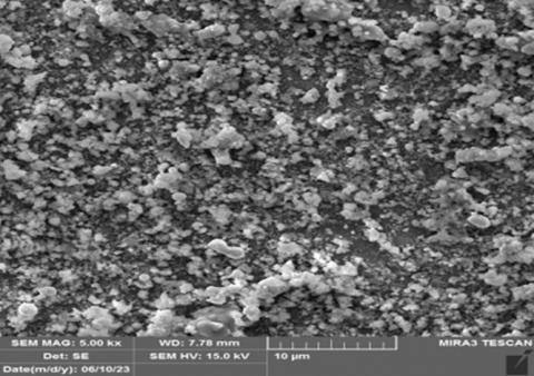
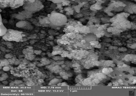
3.2 Field emission scanning electron microscopy (FESEM) results
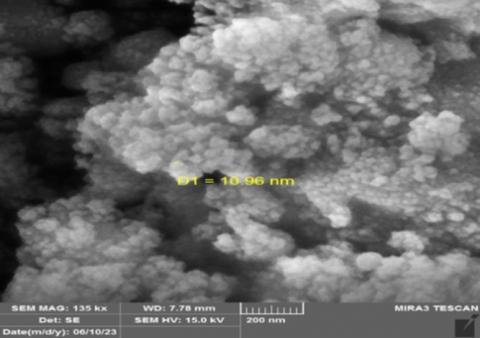
The surface morphology properties of Co2O3 thin films produced by Nd-Yag pulsed laser deposition at a wavelength of 1064 nm were inspected and analyzed using a FESEM device that generates images with a high degree of magnification and resolution. Figure 3 explains the surface morphology of the cobalt oxide (Co2O3) which is characterized by a rise in the rate of granular size and homogeneity with the presence of characteristic shapes (floral). These images, which were enlarged by a factor of 10 μm, 1 μm, 200 nm, demonstrate that the thin film' surfaces are dense and unmistakably indicate a rise in the granular size rate. Based on computations, cobalt oxide films had typically feature grains between 10 and 28 nm in diameter. In general, the cobalt oxide thin films are made up of grains with spherical morphologies and distinctive shapes. The average granular size was measured through the (ImageJ) program and the results obtained showed that the prepared materials have a nanostructure.
Figure 3. Images FESEM for cobalt oxide (Co2O3) thin films
3.3 Optical properties
3.3.1 Linear optical properties
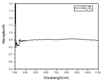
The characteristics of optical thin films composed of Co2O3 have been studied; These investigations provide absorbance curves for 450 nm thickness as a function of wavelength in the range of 300–1000 nm. With the help of the relationship between (Tauc), the optical connectivity and absorbance factor measurements, and the connection, it was possible to determine the forbidden energy gap for direct transitions.
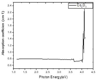
Figure 4 demonstrates that the absorption peak was at a wavelength of 300 nm and was 1.5, then it fell as the wavelength increased. The relationship between the absorbance and the cobalt oxide (Co2O3) films' deposition process using pulsed laser on glass base was also calculated. Figure 5 demonstrates how does the absorbance coefficient (α) relate to, which is reliant based on the entering photon's energy (hv). When there is a greater absorbance coefficient than (104 cm-1), transfers are deemed direct. The absorbance coefficient of 400 nm thick cobalt oxide (Co2O3) coatings was determined [17] using relation (14).
$\alpha=2.303 A / t$ (14)
Figure 4. The absorption for a cobalt oxide (Co2O3) sheet with respect to wavelength
A is the absorbance, and α is the absorption coefficient, where t is the thickness of the thin film. The energy of the incident photons and the characteristics of the material, like energy gaps and different types of electrical transitions between frequency bands, have an impact on the absorption coefficient (α).
Figure 5. Photon energy and absorption coefficient relationship for cobalt oxide (Co2O3) film
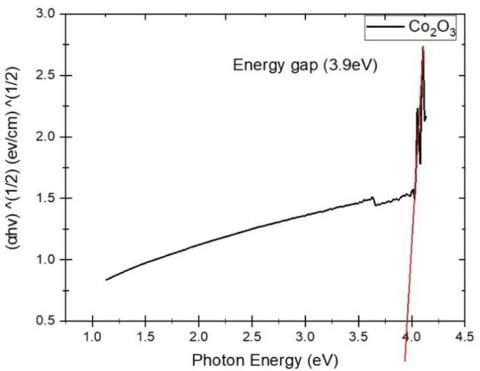
The coefficient of absorption is influenced by the incident photons' energy in addition to material characteristics like energy gaps and other types of electrical transmissions that take place across frequency ranges. The magnitude of the optical component that is most fundamentally impacted by matter structure is energy gap. The cobalt oxide (Co2O3) films' energy gap is constrained by equation Tauc (15) with r = 1/2 [18], allowing for permitted direct electronic transitions:
$\alpha h v=\beta(h v-E g)^r$ (15)
where, β is the medium density and effective mass-based constant, h is the Plank constant, α is the absorption coefficient, and υ is the frequency of the incoming photons, Eg is optical gap, r is constant whose values range from (3, 2, 2/3, 1/2) to depends on the kind of electronic transitions causing your optical absorption [18].
Figure 6. The change in (αhv)² for Co2O3 thin film with the incident photon energy
The straight section connecting photon energy (hν) ½ and (hν) ½ is drawn to remove the photon energy axis at that location (hv) = 0. The energy gap to direct transition of the cobalt oxide (Co2O3) films is (3.9 eV), as shown in Figure 6.
3.3.2 Optically nonlinear properties
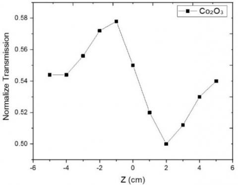
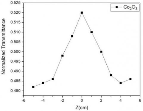
Figures 7 and 8 show the transmittance curve of Co2O3 thin film as dependent on various locations Z-scan with a narrow aperture and the transmittance curve as depending on various locations Z-scan with an open aperture, respectively. The nonlinear refraction index alone is obtained by dividing the transmission magnitudes of the laser beam in the transmission magnitudes in the case of an open aperture by the case of a closed aperture, as shown in Figures 7 and 8. According to the results of Z-scan techniques for Co2O3 thin films, the nonlinear refraction index n2 value is (4.53×10⁻¹⁹ cm2/mW) at wavelength 650 nm, and the nonlinear absorption coefficient is (6.83×10⁻¹⁰ cm/mW) at wavelength 560 nm with power 50 mW. The third order nonlinear optical susceptibility (χ (3)) at wavelength 650 nm with power 50 mW is calculated to be 2.45 ×10⁻⁹ in Table 1. The results obtained utilizing the Z-scan approach for both the near and open apertures taught us that Co2O3 thin film has a self-de-focusing effect and is saturable. We also discovered that the third order nonlinear optical susceptibility of Co2O3 thin film has a high value based on the outcomes of the Z-scan technique for both the close and open apertures, we discovered that Co2O3 thin film has a self-defocusing effect and is saturated absorption. The third order nonlinear optical susceptibility (χ (3)) of Co2O3 thin film has a good value, as well, as we discovered.
Figure 7. The normalised transmittance curve when the closed aperture of Co2O3 thin film at a 650 nm wavelength with 50 mW power as a function of position
Figure 8. The normalised transmittance curve when the open aperture of Co2O3 thin film at a 650 nm wavelength with 50 mW power as a function of position
Table 1. Result of nonlinear optical properties for cobalt oxide (Co2O3) thin film by Z-scan technique
|
λ(nm) |
Power of Laser (mW) |
$\Delta \varnothing$ (rad) |
$\Delta T_{P-V}$ |
$n_2 \times 10^{-19}$ (cm²/mW) |
$\Delta n \times 10^{-15}$ |
Tmax |
$\beta \times 10^{-10}$ (cm/mW) |
$\left|\chi ^{(3)}\right| \times 10^{-9}$ |
|
650 |
50 |
0.192118 |
0.078 |
4.53 |
3.61 |
0.52 |
6.83 |
2.45 |
3.3.3 I-V characteristics
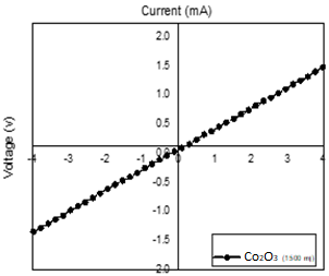
The (I-V) conductivity graphs of a Co2O3 thin film produced at a wavelength of 1064 nm using the Nd-Yag laser pulse deposition technique are shown in Figure 9. The (I-V) characteristics were measured on a glass substrate depleted of cobalt oxide (Co2O3). Current and voltage have a linear relationship, which characterises ohmic behavior. Thus, Ohm's law may be used to adjust the nearly constant resistance. law, and the improved conductivity of a Co2O3 thin sheet has clarified this.
Figure 9. I-V properties of a thin sheet of cobalt oxide (Co2O3)
4.1 Cobalt oxide (Co2O3) film electrical resistors
We looked at the sensitivity characteristics of cobalt oxide (Co2O3) films that were placed on glass flooring. Using NO2 gas that had been generated in a lab, measurements were done. The resistance changed over time at a certain temperature, and the thin films' sensitivity to the gas changed as the temperature changed from 200 to 250 to 300℃. The electrical resistance (R) of the cobalt oxide (Co2O3) thin films was determined as a consequence of temperature and time. At different working temperatures, the resistance was then immediately measured after the temperature was adjusted from 200, 250, and 300℃. Semiconducting materials are distinguished by their resistance, which rises inversely with temperature changes.
4.2 Operating temperature and response time
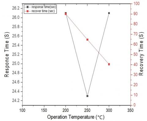
Figure 10. The cobalt oxide (Co2O3) film's reaction and recovery times in relation to its operating temperature
For cobalt oxide (Co2O3) thin films produced on glass substrates, the samples were examined at temperatures ranging from 200 to 300℃. The choice of operating temperature was made based on the sensor's ability to detect gas molecules (NO2). Reaction energy is activated and the sensor will respond when the operating temperature rises to a level where the reaction can happen. The thin film sensitization process is influenced by the thin film's crystalline structure, nano-size granularity, and exposure to external factors.
Furthermore, one of the unique characteristics that restricts the sensor's effectiveness is its response time, which is the amount of time it takes for the sensor to sense and return to its initial state. At an appropriate operating temperature, the faster the sensor responds, the more efficient it is.
The response time for the films produced on glass substrate (in Figure 6), was found to be between 24 and 26 seconds, as shown in Figure 10. Further details on reaction times and operating temperatures are given in Table 2.
Table 2. Cobalt oxide (Co2O3) film's working temperature
|
T |
Tgas(on) |
Tgas(off) |
Tgas Recover |
Response Time (sec) |
Recover Time (sec) |
|
200 250 300 |
21 21 26 |
50 48 55 |
150 120 100 |
26.1 24.3 26.1 |
90 64.8 40.5 |
4.3 Sensitivity
After examining thin film resistance in both the presence and absence of NO2 gas in a time-dependent manner, the glass surface sensitivity of thin layers of cobalt oxide (Co2O3) substrate was determined. Making use of a gas sensor system, the cobalt oxide's sensitivity (Co2O3) thin film was assessed, and the produced films' sensitivity was determined using the equation below [17-19]:
$S=\frac{|\Delta R|}{R \circ} \times 100 \%$
$S=\frac{\text { Rgas }- \text { Rair }}{\text { Rair }} \times 100 \%$
where, Ra is the air resistance, Rg is the NO2 gas's resistance.
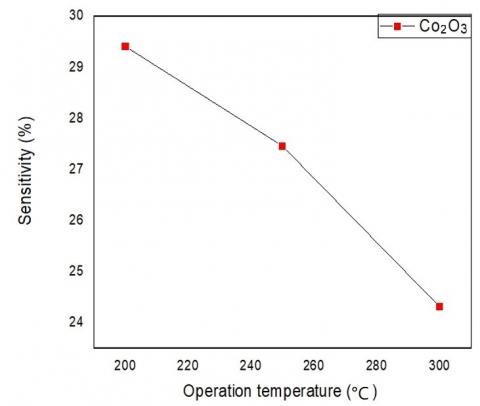
This made it possible to determine the sensitivity of cobalt oxide (Co2O3) films. It revealed that Co2O3 had sensitivity values of (29.407%, 27.458%, 24.3139%) at (200, 250, 300℃).
The Co2O3 nanoparticles' oxygen ions will be absorbed from before the gas molecules when the thin film is exposed to an oxidising gas, such as NO2, which will lower the voltage barrier and the concentration of charge carriers near the edges of the granules. This is the norm for adsorption and gas detection techniques that rely on crystal structures of thin-film materials to enable the oxygen ions in Co2O3 to function, as demonstrated by the data in Table 3.
Table 3. Co2O3 thin film's sensitivity and resistance measure (off when no gas is present and on when gas is present)
|
Sample |
R(MΩ) |
T(℃) |
S% |
|
|
off |
on |
|||
|
Co2O3 |
21.34 12.76 11.58 |
30.23 17.59 15.3 |
200 250 300 |
29.407 27.458 24.313 |
Generate a rise in the voltage barrier at the and a depletion layer. According to the study's findings, cobalt oxide films have a high sensitivity, which is in line with previous research [20, 21].
Cobalt oxide thin film sensitivity to the gas NO2 is shown in Figure 11 with values of (24.313) at 300℃, 27.458% at 250℃, and 29.407% at 200℃.
Figure 11. The sensitivity of cobalt oxide (Co2O3) thin film as a function of operation temperature
The properties of cobalt oxide films prepared by pulsed laser of wavelength 1064, energy of 1500 mJ, vacuum pressure of (8×10⁻²) mbr, and frequency of 6 Hz and deposited on glass substrates were deposited for 450 nm thickness then studied as the morphological form of cobalt oxide films is homogeneous and void-free and in spherical granular shapes. The results also showed the scanning technique that the films have a saturated absorption coefficient and self-de-focusing effect refractive index. Cobalt oxide (Co2O3) Nao films showed a gas NO2 temperature (200, 250 and 300). The results showed that cobalt oxide films can be used in optical power limiter, nonlinear optical photonic device, and a wide range of nonlinear applications and the findings shows the cobalt oxide thin films possess promising applications for different devices for gases.
[1] Gomes, G.C., Borghi, F.F., Ospina, R.O., López, E.O., Borges, F.O., Mello, A. (2017). Nd: YAG (532 nm) pulsed laser deposition produces crystalline hydroxyapatite thin coatings at room temperature. Surface and Coatings Technology, 329: 174-183. https://doi.org/10.1016/j.surfcoat.2017.09.008
[2] Harilal, S.S., Bindhu, C.V., Tillack, M.S., Najmabadi, F., Gaeris, A.C. (2003). Internal structure and expansion dynamics of laser ablation plumes into ambient gases. Journal of Applied Physics, 93(5): 2380-2388. https://doi.org/10.1063/1.1544070
[3] Frey, H., Khan, H.R. (2015). Handbook of Thin Film Technology. Springer, Berlin, pp. 1-379. https://doi.org/10.1007/978-3-642-05430-3
[4] Fujioka, H. (2015). Pulsed Laser Deposition (PLD). In Handbook of Crystal Growth. Elsevier, Amsterdam, pp. 365-397. https://doi.org/10.1016/B978-0-444-63304-0.00008-1
[5] Venkatesan, T. (2013). Pulsed laser deposition: Invention or discovery?. Journal of Physics D: Applied Physics, 47(3): 3-10. https://doi.org/10.1088/0022-3727/47/3/034001
[6] Hashida, M., Mishima, H., Tokita, S., Sakabe, S. (2009). Non-thermal ablation of expanded polytetrafluoroethylene with an intense femtosecond-pulse laser. Optics Express, 17(15): 13116-13121. https://doi.org/10.1364/OE.17.013116
[7] Ojeda-G-P, A., Döbeli, M., Lippert, T. (2018). Influence of plume properties on thin film composition in pulsed laser deposition. Advanced Materials Interfaces, 5(18): 1-16. https://doi.org/10.1002/admi.201701062
[8] Haider, A.J., Alawsi, T., Haider, M.J., Taha, B.A., Marhoon, H.A. (2022). A comprehensive review on pulsed laser deposition technique to effective nanostructure production: Trends and challenges. Optical and Quantum Electronics, 54(8): 488. https://doi.org/10.1007/s11082-022-03786-6
[9] Kumari, V., Kumar, V., Malik, B.P., Mehra, R.M., Mohan, D. (2012). Nonlinear optical properties of erbium doped zinc oxide (EZO) thin films. Optics Communications, 285(8): 2182-2188. https://doi.org/10.1016/j.optcom.2011.12.094
[10] Sheik-Bahae, M., Said, A.A., Wei, T.H., Hagan, D.J., Van Stryland, E.W. (1990). Sensitive measurement of optical nonlinearities using a single beam. IEEE Journal of Quantum Electronics, 26(4): 760-769. https://doi.org/10.1109/3.53394
[11] Rahman, M.A., Alghoraibi, I. (2019). Theoretical investigation of second harmonic efficiency effect on third harmonic conversion efficiency in BBO crystals. Optik, 194: 163031. https://doi.org/10.1016/j.ijleo.2019.163031
[12] Rao, K.S., Ganeev, R.A., Zhang, K., Fu, Y., Boltaev, G.S., Krishnendu, P.S., Guo, C. (2018). Laser ablation–induced synthesis and nonlinear optical characterization of titanium and cobalt nanoparticles. Journal of Nanoparticle Research, 20: 1-15. https://doi.org/10.1007/s11051-018-4391-3
[13] Li, J., Liu, C.Y., Xie, Z. (2011). Synthesis and surface plasmon resonance properties of carbon-coated Cu and Co nanoparticles. Materials Research Bulletin, 46(5): 743-747. https://doi.org/10.1016/j.materresbull.2011.01.014
[14] Fontalvo, M., García, A., Valbuena, S., Racedo, F. (2016). Measurement of nonlinear refractive index of organic materials by z-scan. Journal of Physics: Conference Series, 687(1): 012100. https://doi.org/10.1088/1742-6596/687/1/012100
[15] Carpenter, M.A., Mathur, S., Kolmakov, A. (2012). Metal Oxide Nanomaterials for Chemical Sensors. Springer Science & Business Media. https://doi.org/10.1007/978-1-4614-5395-6
[16] Zhuiykov, S. (2007). Electrochemistry of Zirconia Gas Sensors. CRC Press. https://doi.org/10.1201/9781420047622
[17] Su, P.G., Yang, L.Y. (2016). NH3 gas sensor based on Pd/SnO2/RGO ternary composite operated at room-temperature. Sensors and Actuators B: Chemical, 223: 202-208. https://doi.org/10.1016/j.snb.2015.09.091.
[18] Korotcenkov, G. (2013). Handbook of Gas Sensor Materials. Conventional Approaches. https://doi.org/10.1007/978-1-4614-7165-3
[19] Alnayli, R.S., Khadayeir, A.A., Dayekh, M.L., Hakim, Z. (2020). Study of electrical and gas sensing characteristics of (TiO2/rGO) nanocomposite to NH3 sensor application. Journal of Physics: Conference Series, 1660(1): 012051. https://doi.org/10.1088/1742-6596/1660/1/012051
[20] Dayekh, M., Ghadi, A., Hussain, S.A. (2024). Synthesis of CoO thin films by pulsed laser deposition method; studying an optical, electrical and sensing properties. AIP Conference Proceedings, 3051(1). https://doi.org/10.1063/5.0191604
[21] Abdullah, M.M., Akhtar, M.S., Al-Abbas, S.M. (2018). Facile growth and promising applications of cobalt oxide (Co3O4) nanoparticles as chemi-sensor and dielectric material. Current Nanoscience, 14(4): 343-351. https://doi.org/10.2174/1573413714666180226140732