Mustafa Sami Abdullatef![]()
© 2024 The author. This article is published by IIETA and is licensed under the CC BY 4.0 license (http://creativecommons.org/licenses/by/4.0/).
OPEN ACCESS
In an austenitic stainless steel type ASTM 904L that was cathodically hydrogenated, outgassed, and subsequently tested, the initiation of fatigue cracks was investigated. Tests were run with 50Hz combined loads (bending and torsion) and were paused at different periodsof fatigue life to allow scanning electron microscopy inspection of the gage surface of the samples (SEM). Slip marks were not visible on the surface of the hydrogenated and outgassed material, in contrast to the non-hydrogenated fatigued material. Its tired gage surface has consistently been related with the pre-existing hydrogen-induced fissures and has shown the "peeling off" of extremely thin layers in various locations from the start of the fatigue life. However, it was discovered that the major fatigue crack began subsurfacely, most likely along the boundary between the ductile material inside and the hydrogen-hardened exterior layer. It seems unlikely that the hydrogen-induced surface cracks will be employed as a tool to simulate the fatigue behavior of short fractures in austenitic stainless steels because they do not grow on their own.
austenitic stainless steel, ASTM 904L, combined loading, fatigue crack growth, fatigue initiation,fracture mechanics, hydrogen, short crack
The use of modern alloys and efficient analysis techniques meets the technological requirements for stress and fracture, essential for managing and optimizing component performance in the defense industries, marine industries, energy and renewable energy, aerospace and transportation productions. The fracture resistance of high-strength metal alloys is significantly and extensively reduced by hydrogen. Low amounts of mode I stress intensity factor (K), mode I, cause sub-critical hydrogen cracking. If the hydrogen is not released from the structure of the austenitic steel at a high enough temperature or if mechanical work is performed on the material while the hydrogen is still present, the steel may lose some of its mechanical qualities. Austenitic stainless steels are used in a wide range of hydrogen-rich environments, particularly in the chemical and nuclear industries. If hydrogen is present and the out-gassing occurs near room temperature, some steels are at risk of failure [1].
Because hydrogen is less mobile in austenite than it is in ferrite, there is an accumulation of significant hydrogen content in a very thin layer of the material. According to the chemical makeup of the steel and the resulting degree of austenite instability, high localized levels of strain ensue (as was demonstrated by the use of x-ray techniques [2, 3]), and the following surface effects may be seen:
(1) Austenite may become unstable and partially change into a hcp(ε) martensitic phase during hydrogenation.
(2) In addition to the development of extremely small superficial cracks, another martensitic transition that results in the α' phase may occur during out-gassing.
Due to the large concentration of deformation at these locations, the bcc α' martensitic phase preferentially forms nearby and both nucleate and expand with time following hydrogenation, i.e. with aging time [4].
Internal Hydrogen Assisted Cracking (IHAC) and Hydrogen Environment Assisted Cracking (HEAC) are two types of hydrogen-related crack propagation resistance degradation of high strength alloys. The terms Internal Hydrogen Embrittlement (IHE) and Hydrogen Environment Embrittlement (HEE), respectively, are also used to describe these occurrences. H effects always localize near the crack tip in high strength alloys.
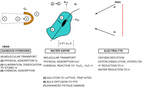
IHAC and HEAC are similar in most respects, with the difference being the source of the harmful H given to the crack tip fracture process zone (FPZ). Figure 1 depicts this viewpoint in summary. As can be seen from Figure 1, the set of atomic processes that, during HEAC for water vapor, an electrolyte or gaseous hydrogen or IHAC for a micro-structure that has already been charged with hydrogen, transport damaging hydrogen to the crack tip fracture process zone. The plastic zone's outside limit is indicated by the dotted line. Maximum crack tip tensile stresses are proportional to K2/σYS E at a distance from the tip [5].
Manufacturing processes (such as casting, welding, surface-chemical cleaning, electrochemical machining, electroplating, and heat treatment) as well as environmental exposure (such as cathodic electrochemical reactions at low temperatures and gaseous hydrogen exposure at elevated temperatures) can introduce atomic hydrogen globally throughout the microstructure. Subcritical fracture growth takes place then under stress, the hydrogen-charged metal, as can be seen in Figure 1's right side. Loading causes dissolved hydrogen to be transferred from the local microstructure to the process zone at the fracture tip, which promotes crack propagation. Since the loading environment is normally benign, stress is not necessary for the uptake of hydrogen, therefore ecological hydrogen generation at the tip of crack when straining is insignificant [5].
Figure 1. The set of atomic processes that transfer harmful hydrogen to the region of the crack tip fracture process [5]
Mechanical loading and chemical reaction work together to create hydrogen environment assisted cracking (HEAC), as can be seen in the left and bottom of Figure 1, most of the time, clean fracture surfaces that are confined near the tip are where atomic hydrogen is formed. H absorption into the crack tip FPZ and subsequent embrittlement come next. As demonstrated for three settings, the fracture tip surface responses are provided by mass transfer of the components of the surrounding environment that is particular to the occluded crack volume. Atomic hydrogen (H) is created, in order from left to right, by dissociative chemical adsorption for H2, chemical reactions for gases like water vapor or H2S, or electrochemical cathodic reactions for acidic or alkaline electrolytes. Once created, the H diffuses into the FPZ in front of the crack tip and causes damage. For alloys in aqueous H2S-bearing electrolytes, the hydrogen mechanism for stress corrosion cracking (SCC) and sulfide stress cracking is provided by this scenario. At the crack tip, electrochemical processes that result in metal dissolution and passive film generation may also be occurring at the same time as H production [5].
The brittle propagation of small fatigue cracks in samples of WT3-1 titanium alloys examined by simultaneous bending and torsion was attempted to be explained by Kocanda et al. [6]. Hydrogen that is taken in from the atmosphere and enters the edges of microcracks in the material's subsurface layer is thought to have an impact on the fracking process. The idea that the action of hydrogen is responsible for the brittle propagation of short fatigue fractures is confirmed by the higher amounts of hydrogen observed near the crack lips located near the sample surface compared to the bulk of the sample.
Cheng and Chen [7] proposed a corrosion-crack correlation model for hydrogen embrittlement (HE) influenced by carbon steel pipeline fatigue crack formation under gaseous hydrogen circumstances. The model is primarily based on the association between the plastic area and the environmental affected zone (EAZ). The Foreman equation predicts the fatigue crack growth rate in the model to take fracture toughness into account. The hydrogen-enhanced decohesion (HEDE) hypothesis and the stress diffusion of hydrogen are used to derive the critical frequency and "transitional" stress intensity factor (K), which offers a plausible explanation for the frequency dependence of fatigue crack growth of a carbon steel tube in hydrogen gas. Additionally, a rough calculation that incorporates the strain ratio and K band threshold.
Based on several observational techniques, including electron backscattering diffraction (EBSD), electron channel contrast imaging (ECCI), and transmission electron microscopy (TEM), Birenis et al. [8] generated a new model of hydrogen-assisted fatigue crack growth (HAFCG) in BCC iron under gaseous hydrogen environment was developed to elucidate the exact mechanism of HAFCG. The non-accelerating regime in the range of a relatively low stress intensity factor, ∆K, and the accelerating regime at a relatively high ∆K were the two distinct regimes that could be distinguished in the FCG of gaseous hydrogen. While quasi-cleavage patterns were seen mostly in the accelerated phase, the ductile and intergranular trans-granular features covered the fracture surface in the non-accelerated regime. In the accelerated regime, the data from EBSD and ECCI showed significantly less plastic deformation, or plasticity, around the crack path.
In the study by Schippl et al. [9], the experimentally determined rate of growth for short stress fractures for an uncharged sample evaluated in air was compared to the findings for samples tested in a 10MPa hydrogen atmosphere and samples that had already been charged with hydrogen. A simulation method to predict the formation of short stress cracks is described in order to further study the hydrogen-related short diffusion mechanisms. The stresses and displacements of anisotropic elastic solids are calculated using the boundary element approach. In the microstructure, the hydrogen concentration is thought to be distributed uniformly. According to this modeling approach, grain boundary cracking in samples evaluated at 10MPa hydrogen is caused by hydrogen due to increased irreversible deformation processes at the crack tip. The impact of tiny traps on the development of hydrogen-assisted fatigue cracks has been studied by Fernández-Sousa et al. [10]. In order to do this, a unique formulation is presented and computationally applied that combine’s strain-assisted multi-trap diffusion, gradient plasticity based on the gradient mechanism, and the fatigue- and hydrogen-dependent cohesion zone model. The findings indicated that the ratio of loading frequency to effective propagation regulates the behavior of fatigue crack growth. Lower rates of fatigue crack propagation are obtained by increasing the density of advantageous traps that are not participating in the cracking process. The foundation for a logical design of hydrogen-resistant alloys is established by identifying the combinations of loading frequency and carbide trap density that reduce embrittlement.
Brück et al. [11] investigated the effects of hydrogen on the fatigue behavior of the high strength martensitic stainless steel X3CrNiMo13-4 and the metastable austenitic stainless steel X2CrNi19-11 with varying nickel concentrations under both high and low cycle fatigue cases. The improvements to the mechanics of propagation for short crack were the main focus of the investigations. Tests were performed with precharged and uncharged samples in compressed hydrogen in laboratory air. The current study set out to identify and quantitatively quantify the main mechanisms of hydrogen embrittlement, as well as how these mechanisms affect the form and rate of propagation of small fatigue cracks. Simulations were conducted to gain a thorough understanding of brief fatigue crack propagation. In addition, the simulation model could accurately predict crack growth and crack route.
Medium manganese steels were annealed at two typical inter-critical annealing temperatures before undergoing fatigue crack growth (FCG) tests, yielding different fractions from austenite (γ) to ferrite (α) and stability (Meta-) in the study of Wan et al. [12]. In a scanning electron microscope used in an environment, a novel hydrogen plasma charge in situ and cyclic in situ loading (ESEM) was coupled. By comparing hydrogen plasma charging in situ to reference tests conducted in vacuum, the fatigue crack growth rate (FCGR) increased by up to twice as much. In the hydrogen environment, fractographic studies revealed brittle-like boundary cracks or fissures, while in the absence of hydrogen, they revealed ductile transgranular cracks. Compared with the fracture path generated by hydrogen in vacuum, the plastic deformation zone of both materials had a smaller size. The hydrogen-assisted FCG of medium-Mn steel with different microstructures was compared, and differences were explained by yielding strength, hydrogen dispersion, phase stability and phase fraction. This thorough analysis can help with understanding the FCG mechanism with or without hydrogen under in-situ hydrogen charging conditions and provide some application-related insights.
The purpose of Briottet et al. [13] is to discuss the precise structural and mechanical features of fatigue crack initiation and propagation in quenched and tempered (Q&T) low alloy steels at ambient temperature and hydrogen pressures between 0.5 and 35 MPa to what metallic components, including pressure vessels such as compressors, are subjected to. And valves for high-pressure hydrogen gas along the hydrogen supply chain. It is necessary to conduct on-site tests under hydrogen pressure for this type of steel. The impact of hydrogen gas on fracture initiation and propagation over the course of the lifetime is examined. The experimental techniques used to detect cracks before they begin in a hydrogen pressure vessel have been reviewed.
According to the aforementioned studies, the fracture surface of the exhausted specimens made steps when they were hydrogenated, whereas the fracture surface of the non-hydrogenated ones was often flat. The simultaneous expansion of various surface fractures caused by hydrogen during fatigue of the various metals employed in the aforementioned researches was used to explain this. Later it was found that these facts might be explained by looking at the occurrence of fatigue fracture initiation on hydrogenated and out-gassed samples in an austenitic stainless steel type ASTM 904L. To accomplish this was one of the paper's stated objectives. Another objective was to determine if hydrogen-induced surface cracks that could be generated in a controlled manner might be used to simulate the fatigue behavior of small fractures in austenitic stainless steels.
2.1 Material
Grade 904L austenitic stainless steel is low carbon, high alloy, and non-stabilized. This grade's resistance to powerful reducing acids, especially sulfuric acid, has been significantly improved by the addition of copper. Additionally, it has outstanding resistance to chloride attack, including stress corrosion cracking, pitting, and crevice corrosion. This grade offers good weldability and formability and is nonmagnetic. Due to its austenitic composition, this grade possesses outstanding endurance, even at freezing temperatures. In rather considerable levels, 904L contains the expensive metals nickel and molybdenum [14].
Corrosion resistance: Although it was initially developed to have a high resisting to sulfuric acid and it has very strong resilience against a variety of other conditions as well. It should be highlighted that the product performs admirably when exposed to warm seawater and high chloride levels. The higher nickel content greatly increases resistance to stress corrosion cracking as compared to traditional austenitic grades. Copper increases resistance to sulfur and other reducing acids.
Resistance to heat: Despite having good oxidation resistance, this heavily alloyed grade experiences structural instability at high temperatures (brittle phases precipitating as sigma). Use shouldn't be permitted above 550℃. The ASME Boiler and Pressure Vessel Code specify the design stress values for the 904L up to 371℃.
Heat treatment (Solution Treatment-Annealing): Heat to between 1090 and 1775℃, then quickly cool. Heat treatment cannot be used to make this grade harder.
Welding: Any common procedure can be used to properly weld 904L. It is crucial to exercise caution because this grade fully austenitic solidifies, making it susceptible to hot cracking, especially in small weldments. Pre-heating is not recommended, and heat treatment after welding is generally not necessary either.
Widespread applications: Processing of paper and pulp, parts of gas-cleaning facilities, equipment for freezing saltwater, elements of an oil refinery, and wires for electrostatic precipitators are some examples of the industries that use these materials.
2.2 Experimental procedure
A hot rolled sheet with a thickness of about 5.0mm of ASTM type 904L stainless steel was used in this work, having the chemical composition, mechanical properties, and physical properties are listed in Tables 1-3, respectively.
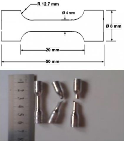
Machined parallel to the rolling direction, round fatigue specimens (see Figure 2a) with a minimum gage width of 20mm and a gage radius curvature of 38.1 mm were heated to 1100℃, and then quenched in water. As illustrated in Figure 3a, this resulted in a mean grain size of 69.7 m and a hardness of 148 Vickers. All micro-hardness measurements were taken with load of 50 g.
Cathodic hydrogenation was carried out at room temperature over a 4-hour period with a current density of 1000 A/m2 and an electrolyte of H2SO4 1N containing 100 mg/l of As2O3. After hydrogenation, the samples were aged for a week at ambient temperature and air pressure before testing, which caused martensitic phase and surface cracks (Figure 3b), as the majority of the hydrogen added during the electrolytic charging process was expelled. The sample that had been out-gassed and hydrogenated had a 192 Vickers hardness.
Table 1. Chemical composition of an austenitic stainless steel type ASTM 904L[14]
|
Grade |
C |
Mn |
Si |
P |
S |
Mo |
Ni |
Cu |
N |
|
|
904L [14] |
min. max |
___ |
____ |
____ |
____ |
____ |
19.0 |
4.0 |
1.0 |
- |
|
0.020 |
2.00 |
1,00 |
0.045 |
0.035 |
23.0 |
5.0 |
2.0 |
0.100 |
||
|
Measured* |
0.013 |
1.8 |
0.6 |
0.029 |
0.033 |
20.1 |
4.2 |
2.0 |
0.055 |
|
Table 2. Mechanical properties an austenitic stainless steel type ASTM 904L
|
Grade |
Tensile Strength (min) inKsi(MPa) |
Yield Strength (min) in Ksi (MPa) |
Elongation (% in 50mm) min |
Modulus of Elasticity (GPa) |
Hardness |
|
|
(HR B)Min Rockwell B |
HBBrinell |
|||||
|
904L [14] |
490 |
220 |
35 |
200 |
90 |
--- |
|
Measured* |
62.35 (430) |
34.08 (235) |
4.5 |
208 |
98 |
155 |
Table 3. Physical properties ofan austenitic stainless steel type ASTM 904L
|
Grade |
Density (kg/m3) |
Mean Coefficient of Thermal Expansion |
Thermal Conductivity at 20℃ (W/m.K) |
Specific Heat 0-100℃ (J/kg.K) |
Electrical Resistivity(nΩ.m) |
|
904L [14] |
8000 |
15.0 |
13.0 |
500 |
850 |
|
Measured* |
7894 |
--- |
14.2 |
488 |
811 |
Note: *At the Specialized Institute for Engineering Industries-Baghdad/Iraq, the samples were tested.
(a)
(b)
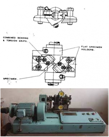
Figure 2. Fatigue test (a) Avery 7305 test machine; (b) Fatigue test specimen (for combined loading bending-torsion) [15]
Figure 3. Initial microstructure of an austenitic stainless steel type ASTM 904L: a) Non-hydrogenated, electrolitically etched with 40% H2O+60% HNO3, J=500 A/m2, t=120 sec at room temperature; and b) Hydrogenated and out-gassed
Table 4. Number of cracks per unit area (N/A) as a function of the current density (J) used for a two-hour cathodic hydrogenation of 904L at room temperature
|
J A/m2 |
50 |
100 |
250 |
1000 |
2500 |
5000 |
10000 |
|
N/A×103 Cracks/mm2 |
79.1 |
28.9 |
159.8 |
220.2 |
249.0 |
310.5 |
318.8 |
Due to the limited depth of hydrogen penetration into austenite, the morphological and quantitative characterization of these surface fractures revealed that they are very small (with an average length lower than the grain diameter) and very shallow. They are produced in huge quantities and have a crystalline appearance with various orientations in different grains, as evidenced by the findings in Table 4.
The Avery 7305 test machine (Figure 2b) was used to conduct the fatigue test under constant amplitude stress and stress ratio (R=-1) in a lab setting with combined loading (bending-torsion) at a frequency of 50 Hz. A scanning electron microscope (SEM) was used to inspect the lateral surfaces of the gage section at various points during the fatigue life in order to study the initiation and growth of fatigue cracks.
All of the results used to describe the fatigue behavior in the current work are consistent with a 195 MPa degree of stress. The fatigue life of the non-hydrogenated specimens for this situation was determined to be 317,000 cycles, but the hydrogenated out-gassed samples' fatigue life was 101,000 cycles, or roughly 32% of the former.
The surface of the tired samples that had been hydrogenated and out-gassed first showed the peeling off of extremely thin coatings in a few localized areas throughout the gage section. This is shown in Figure 4a and Figure 4b, and it appears to be the result of a very weak section of the outermost surface cracking, possibly in conjunction with already existing hydrogen-induced microcracks. Due to their elevation above the surface plane in the micrographs, these fragmented patches look whiter. They appear as soon as a few fatigue cycles are applied to the material and don't really alter throughout the course of the fatigue life. Some of them finally come off the material on their own. The hydrogen-induced microcracks, however, were not seen to lengthen throughout the course of the fatigue life.
Figure 4. Detail of the surface at the gage surface of hydrogenated and out-gassed sample fatigue to 20% of fatigue life; subgraph (b) is an enlargement of the area included in subgraph (a)
The major fatigue crack appeared in the same region of the surface of a specific specimen used as an example in all of the samples that were observed, as shown in Figures 5-7. On the gage surface of the specimens, several dark patterns, like the one in Figure 5, were seen to develop and enlarge with increasing numbers of fatigue cycles. One of them was consistently discovered to be connected to the primary fatigue crack that caused the fracture, as seen in Figure 7. Briefly stated, the major crack initially appeared as a dark mark on the surface and developed sub-superficially. The major fatigue fracture didn't begin to manifest itself as a surface crack until the end of the fatigue life. After the sample had been cycled through 49% of its fatigue life, a photograph of the sub-superficial crack shown in Figure 5 was taken.
Figure 5. Early indication of the fatigue subsurface crack appearing on the surface of the hydrogenated and out-gassed sample at the gage surface at 50% of its fatigue life
It is interesting to note that it spreads transgranularly, passing through grains that have and do not have hydrogen-induced surface cracks indistinctly. Since it does not follow the direction of these cracks, it cannot be assumed that it was primarily formed as a result of the deepening of hydrogen-induced cracks. The micrograph in Figure 6 was taken after the sample had been cycled for around 63% of the fatigue life and shows the same sub-superficial crack as Figure 5 but over a significantly longer period of time. The white markings (white lines) in Figures 5 and 6 show the locations of intergranular and transgranular surface fissures brought on by hydrogen. The martensitic phases (labeled A) may be seen in a few areas of Figure 5, which was magnified. Additionally, no connection between these phases and the subsurface fissures was discovered.
Figure 6. Growing of the feature associated with the subsurface fatigue crack for the hydrogenated and out-gassed specimen at 70% of the fatigue life, includes the area shown in Figure 5
Finally, the crack at the end of the fatigue life can be seen in Figure 7 in the same area that was circled in Figure 6.
Figure 7. Fatigue crack on the gage lateral surface at extingued fatigue life of the hydrogenated and out-gassed sample, corresponds to the area indicated by the red circle in Figure 6
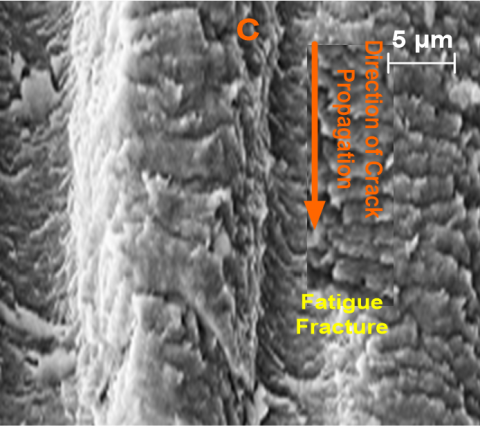
Figure 8 depicts the fracture surface in the area shown on the upper left side of Figure 6. It's interesting to note that the step on the fracture surface seen in Figure 8 exactly matches the hump in the sub-superficial crack that appears on the upper left side of Figure 6 to the left of the white circle.
Figure 8. Detail of a step on the fracture surface of a fatigued hydrogenated out-gassed sample. The step corresponds to the hump on the squared region B in Figure 6
Figure 9, on the left side of Figure 8, shows a detail of the upper portion of this step that is closer to the sample's surface. This micrograph demonstrates the presence of secondary fractures, one of which seems to originate from a surface break that may have been caused by hydrogen (designated C in Figure 9). Observations made with a scanning electron microscope (SEM) comprised a close investigation of the fracture surfaces and the lateral surfaces of the hydrogenated out-gassed samples. Despite this, no definite evidence of the primary fatigue crack's initiation locations was discovered, most likely as a result of the very uneven fracture surfaces.
Figure 9. Magnification of a region of Figure 8 at the top left of the step on fracture morphology near by the lateral surface of a fatigued hydrogenated out-gassed sample (showing secondary fatigue crack, Mark C)
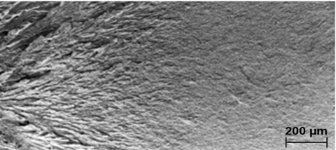
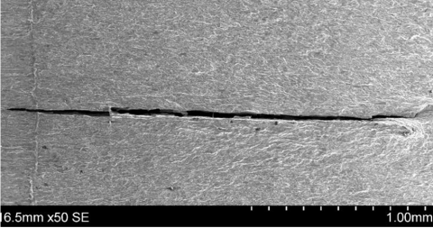
A thorough investigation of the fatigue crack's initiation and propagation characteristics in the non-hydrogenated material was not one of the paper's goals. However, Figure 10 illustrates the characteristics of the propagation of the fatigue fracture in a non-hydrogenated specimen evaluated under the identical circumstances as the hydrogenated out-gassed samples for the purpose of comparison. There are numerous slide marks can be seen.
Figure 10. Fatigue crack on the lateral gage surface of a non-hydrogenated sample. Shows many slip marks due to the accumulated fatigue strain
Recent research has focused on the start and spread [16-21] of fatigue fractures in austenitic stainless steels and other face-centred cubic structure materials (f.c.c) [22, 23]. It was discovered that deformation markings, along with a certain degree of surface roughness, occur early in the fatigue life and are followed by the nucleation of superficial microcracks. As the main fatigue fracture continues to merge and form, these microcracks increase in size and number. In terms of the typical creation of slip markings on the surface of the fatigue non-hydrogenated samples, the behavior depicted in Figure 10 was also documented in the literature [24-26].
It was discovered that the fatigue behavior of the hydrogenated and out-gassed specimens was very different. First off, there were no slip markings visible on the surface of the specimen for the condition represented by the present data, not even at the site of fracture, indicating that the surface layer had not undergone plastic deformation. Additionally, no expansion of pre-existing hydrogen-induced cracks and/or the formation of fatigue microcracks on the surface were seen throughout the fatigue life.
Surprisingly, it was discovered that the fatigue fractures began supra-superficially rather than, as could be anticipated, as a result of the expansion and coalescence of the pre-existing hydrogen-induced cracks. The existence of a hardened surface layer (as previously indicated), the presence of hydrogen-induced surface cracks and martensitic phases, as well as the role played by the peeled-off portions, are only a few of the variables that may have an impact on the onset of the fatigue cracks. Because hydrogen penetration into the material varies greatly depending on the local microstructure, the hydrogen-induced hardened surface layer may have an uneven depth. For the current hydrogenation state, the mean depth can be approximated as follows. It can be assumed that the hydrogen diffusion coefficient D in austenite at 296 K has a value of 1.38×10⁻¹⁶ m2/s [27]. The diffusion in a semi-infinite material has the following Fick's law solution:
$\frac{C}{C_0}=1-\operatorname{erf}\left[\frac{x}{2 \sqrt{D t}}\right]$ (1)
where, C0 is the concentration of hydrogen in the surface, C is the concentration at depth x and t is the time of hydrogenation (=14.4 sec. for the present case). Assuming that the hydrogen affected region of the material extends to a depth in which the hydrogen concentration is 0.1% of that found in the surface (i.e. C/(C0=0.001)) and applying the present conditions in Eq. (1), one obtains an average depth of the order of 6 μm which is of the same order of magnitude of the experimental determinations [3, 4, 11, 14] mentioned before. This makes it clear that the effects induced by hydrogen are indeed concentrated in a very thin surface layer, which becomes hardened.
The hydrogenated out-gassed specimens then act as a "composite material" with a flexible core encircled by a hard, thin surface layer that contains microcracks. This layer fractures easily along the pre-existing hydrogen-induced fissures because it is unable to plastically withstand the strains put on it during the fatigue test. However, it is not discovered that this effect is connected to the beginning or growth of the primary fatigue crack. The sample's effective cross section is decreased as a result of the peeling off effect, but this reduction is too modest to account for the observed decrease in fatigue life. With the exception of the fact that in the latter case the presence of a hardened surface layer often improved the fatigue life, this scenario is remarkably similar to what is seen in a shot peened material. The fatigue crack starts off sub-superficially in both situations. The hydrogen-induced hardened layer differs from the shot peened one in at least two aspects. Both the existence of delayed surface cracks and the likelihood that this layer's depth profile is uneven due to microstructural inhomogeneities are examples of this.
Hydrogen penetration is heterogeneous due to differences in the steel's microstructure (such as grain and twin boundaries, second phase particles, slip bands, and localized constitutional segregation), which gives rise to the previously mentioned hardened surface layer with an irregular depth profile upon out-gassing. In turn, this might make it easier for fatigue sub-surface cracks to form in a number of locations around the point where the hardened layer and the ductile material within meet. As a result, in hydrogenated out-gassed samples as opposed to non-hydrogenated ones, the onset of the fatigue cracks would be quicker. The observed reduction in fatigue life may have been the result of this.
On the other hand, even if it is discovered that the pre-existing hydrogen cracks do not expand throughout the fatigue life, they may ultimately be the cause of the formation of secondary fatigue cracks, which may then expand and combine to produce the main crack. In essence, the fracture denoted by the letter C in Figure 9 appears to have started in a hydrogen-induced surface crack. This result could also account for the observed decrease in fatigue life.
Despite the fact that the main fatigue crack's initiation sites were not precisely identified, two hypotheses were put up to explain this initiation:
They may eventually both work together or individually to shorten the fatigue life. The depth of the main fatigue crack may change and become wavy, as in Figures 5 and 6. This is due to the presence of several secondary fatigue cracks. This explains why there are characteristics like the hump on the left side of Figure 6 that contribute to the fracture morphology's steps. Finally, it would not be appropriate to use the hydrogen-induced surface cracks as a tool to model the fatigue behavior of short cracks in austenitic stainless steels due to the intricacy of the initiation characteristics in this material.
The authors would like to thank the Department of Electromechanical Engineering at the University of Technology in Baghdad, Iraq for its contribution in support to carry out this research.
|
E |
Modulus of elasticity |
|
|
FPZ |
Fracture process zone |
|
|
HEAC |
Hydrogen Environment Assisted Cracking |
|
|
HEE |
Hydrogen Environment Embrittlement |
|
|
IHE |
Internal Hydrogen Embrittlement |
|
|
K |
Stress intensity factor |
|
|
KC |
Critical stress intensity factor |
|
|
Ktc |
Fracture toughness |
|
|
SCC |
Stress corrosion cracking |
|
|
Greek symbols |
||
|
σYS |
Yield stress |
|
|
α' |
Bcc martensitic phase |
|
|
εP |
Plastic strain |
|
[1] Takakuwa, O., Yamabe, J., Matsunaga, H., Furuya, Y., Matsuoka, S. (2017). Recent progress on interpretation of tensile ductility loss for various austenitic stainless steels with external and internal hydrogen. In Pressure Vessels and Piping Conference. American Society of Mechanical Engineers, 58004: V06BT06A041. https://doi.org/10.1115/PVP2017-65671
[2] Astafurova, E.G., Moskvina, V.A., Maier, G.G., Melnikov, E.V., Zakharov, G.N., Astafurov, S.V., Galchenko, N.K. (2017). Effect of hydrogenation on mechanical properties and tensile fracture mechanism of a high-nitrogen austenitic steel. Journal of Materials Science, 52: 4224-4233. https://doi.org/10.1007/s10853-016-0676-z
[3] Godoi, W., Kuromoto, N.K., Guimaraes, A.S., Lepienski, C.M. (2003). Effect of the hydrogen outgassing time on the hardness of austenitic stainless steels welds. Materials Science and Engineering: A, 354(1-2): 251-256. https://doi.org/10.1016/S0921-5093(03)00014-5
[4] Tabata, T., Birnbaum, H.K. (1983). Direct observations of the effect of hydrogen on the behavior of dislocations in iron. Scripta Metallurgica, 17(7): 947-950. https://doi.org/10.1016/0036-9748(83)90268-5
[5] Gangloff, R.P. (2003). Hydrogen assisted cracking of high strength alloys. Comprehensive Structural Integrity, 6(31-101).
[6] Kocanda, D., Kocanda, S., Lunarska, E., Mierzynski, J. (2005). Possibility of hydrogen-assisted propagation of short fatigue cracks in WT3-1 titanium alloy. Materials Science, 41: 304-308. https://doi.org/10.1007/s11003-005-0166-y
[7] Cheng, A., Chen, N.Z. (2017). Fatigue crack growth modelling for pipeline carbon steels under gaseous hydrogen conditions. International Journal of Fatigue, 96: 152-161. https://doi.org/10.1016/j.ijfatigue.2016.11.029
[8] Birenis, D., Ogawa, Y., Matsunaga, H., Takakuwa, O., Yamabe, J., Prytz, Ø., Thøgersen, A. (2018). Interpretation of hydrogen-assisted fatigue crack propagation in BCC iron based on dislocation structure evolution around the crack wake. Acta Materialia, 156: 245-253. https://doi.org/10.1016/j.actamat.2018.06.041
[9] Schippl, V., Brück, S., Christ, H.J., Fritzen, C.P., Schwarz, M., Weihe, S. (2018). Modeling of hydrogen effects on short crack propagation in a metastable austenitic stainless steel (X2CrNi19-11). In MATEC Web of Conferences. EDP Sciences, 165: 22005. https://doi.org/10.1051/matecconf/201816522005
[10] Fernández-Sousa, R., Betegón, C., Martínez-Paneda, E. (2022). Cohesive zone modelling of hydrogen assisted fatigue crack growth: The role of trapping. International Journal of Fatigue, 162: 106935. https://doi.org/10.1016/j.ijfatigue.2022.106935
[11] Brück, S., Schippl, V., Schwarz, M., Christ, H.J., Fritzen, C.P., Weihe, S. (2018). Hydrogen embrittlement mechanism in fatigue behavior of austenitic and martensitic stainless steels. Metals, 8(5): 339. https://doi.org/10.3390/met8050339
[12] Wan, D., Ma, Y., Sun, B., Razavi, N., Wang, D., Lu, X., Song, W. (2021). Evaluation of hydrogen effect on the fatigue crack growth behavior of medium-Mn steels via in-situ hydrogen plasma charging in an environmental scanning electron microscope. Journal of Materials Science & Technology, 85: 30-43. https://doi.org/10.1016/j.jmst.2020.12.069
[13] Briottet, L., Moro, I., Escot, M., Furtado, J., Bortot, P., Tamponi, G.M., Solin, J., Odemer, G., Blanc, C., Andrieu, E. (2015). Fatigue crack initiation and growth in a CrMo steel under hydrogen pressure. International Journal of Hydrogen Energy, 40(47): 17021-17030. https://doi.org/10.1016/j.ijhydene.2015.05.080
[14] Steels, A. (2013). Stainless steel grade datasheets. Atlas Steels Technical Department: Melbourne, Australia.
[15] Abdullatef, M.S., Al-Tamimi, A., Alzubaidi, F.N., Mahmood, Y.A. (2023). Analysis of the joint effect of heat treatments and stress ratio on the growth behavior of fatigue cracks in cast aluminum alloys under combined loading (bending-torsion). Journal of Composite & Advanced Materials/Revue des Composites et des Matériaux Avancés, 33(2). https://doi.org/10.18280/rcma.330202
[16] Mazánová, V., Polák, J. (2018). Initiation and growth of short fatigue cracks in austenitic Sanicro 25 steel. Fatigue & Fracture of Engineering Materials & Structures, 41(7): 1529-1545. https://doi.org/10.1111/ffe.12794
[17] Issam, B., Rassim, Y., Abdelhek, I., Amokrane, B.M., Abdelhamid, S. (2019). Simulation and numerical modeling of mechanical properties of stainless steel mold X39CrMo17-1. Revue des Composites et des Matériaux Avancés, 29(6): 351-355. https://doi.org/10.18280/rcma.290602
[18] Nani Babu, M. (2019). Fatigue crack growth behavior of nitrogen bearing austenitic stainless steel and its weld: Analysis using unified approach. Ph.D. Thesis, Homi Bhabha National Institute, Indira Gandhi Centre for Atomic Research.
[19] Mekky, A.B.H. (2020). Computational modelling for specific heat and thermal conductivity of austenitic stainless steels alloys at solid phase. Revue des Composites et des Matériaux Avancés, 30(1): 23-27. https://doi.org/10.18280/rcma.300104
[20] Abdullatef, M.S., AlRazzaq, N., M Hasan, M. (2016). Prediction fatigue life of aluminum alloy 7075 T73 using neural networks and neuro-fuzzy models. Engineering and Technology Journal, 34(2): 272-283. https://doi.org/10.30684/etj.2016.112624
[21] Makhatha, M.E., Baruwa, A.D., Gonya, E. (2022). Grain boundary and microstructural characterization of heat-treated as-rolled 2205 duplex stainless steel. Revue des Composites et des Materiaux Avances, 32(6): 285. https://doi.org/10.18280/rcma.320604
[22] Abdullatef, M.S., Alzubaidi, F.N., Al-Tamimi, A., Mahmood, Y.A. (2023). Fatigue life estimation of high strength 2090-t83 aluminum alloy under pure torsion loading using various machine learning techniques. Fluid Dynamics & Materials Processing, 19(8): 2083-2107. http://doi.org/10.32604/fdmp.2023.027266
[23] Abdullateef, M.S. (2013). Study of short cracks growth behavior for duralumin 7075-t6 enhanced by artificial ageing as thermal and chemical treatments under rotating bending loading. Engineering and Technology Journal, 31(11 Part (A) Engineering): 2166-2182.
[24] Hu, Y., Chen, Y., He, C., Liu, Y., Wang, Q., Wang, C. (2020). Bending fatigue behavior of 316L stainless steel up to very high cycle fatigue regime. Materials, 13(21): 4820. https://doi.org/10.3390/ma13214820
[25] Eterashvili, T. (2017). Study of fracture mechanisms at cyclic fatigue of austenitic steels used in nuclear reactors. In Austenitic Stainless Steels-New Aspects. IntechOpen. https://doi.org/10.5772/intechopen.70953
[26] Eterashvili, T., Dzigrashvili, T., Vardosanidze, M. (2015). Deviations of microcrack during propagation in thin films of austenitic steel and accompanying accommodative processes. Key Engineering Materials, 627: 297-300. https://doi.org/10.4028/www.scientific.net/KEM.627.297
[27] Gorban, A.N., Sargsyan, H.P., Wahab, H.A. (2011). Quasichemical models of multicomponent nonlinear diffusion. Mathematical Modelling of Natural Phenomena, 6(5): 184-262. https://doi.org/10.1051/mmnp/20116509