Anfal Mansur Hameed![]() | Samah Ahmed Hardan
| Samah Ahmed Hardan![]() | Hadeel R. Khatab*
| Hadeel R. Khatab*![]()
© 2024 The authors. This article is published by IIETA and is licensed under the CC BY 4.0 license (http://creativecommons.org/licenses/by/4.0/).
OPEN ACCESS
The utilization of fiber-reinforced polymers (FRP) as strengthening agents has been widely employed to improve the flexural and shear strength of reinforced concrete (RC) beams. However, research on enhancing the strength of reinforced concrete (RC) beams under torsional forces through the application of fiber-reinforced polymer (FRP) wrapping or Near-Surface Mounted (NSM)-FRP is few. This work utilizes ABAQUS/CAE version 2019 finite element (FE) software to conduct nonlinear numerical simulations. The purpose is to investigate the torsional-flexural behavior of reinforced concrete (RC) beams that have been reinforced with either fiber-reinforced polymer (FRP) wrapping or near-surface mounted (NSM) FRP bars. Comparing computational and experimental models showed that the experimental model's final torque and angle of twist averaged 1.016 and 0.89 for the numerically investigated components. The results show that changing the inclination angle of the bar or sheet from 90 to 45º has a significant impact on the ultimate torque Tu, where the changing of the inclination angle from 90 to 45º increased the Tu by about (14.13, 13.39 and 13.83%) for beams with an inclination angle of 45º (with CFRP sheets spacing of 150 mm, with NSM bars spacing of 200 mm, and with CFRP sheets spacing of 150 mm and longitudinal CFRP sheet ) with respect to the similar beam for each one but with inclination angle of 90º, which means that changing the inclination angle of the bar or sheet from 90 to 45º increases the torsional stiffness of the beam. Longitudinal CFRP or NSM reinforcement increases beam torsional and bending stiffness. Reducing the NSM bar gap increases beam torsional and shear stiffness.
ABAQUS, torsional performance, fiber reinforced polymer (FRP) wrapping, nonlinear behavior, crack patterns, near-surface mounted NSM
In the last 30 years, there has been a lot of interest in the way that FRP composite materials can be used to strengthen structures. In recent years, there are many works done to enhance the flexural and shear behavior of RC beams by adding FRP sheets that are bonded on the outside. Very little research has been done on how to strengthen torsional members with FRP composites, and there aren't many data or design guidelines in the literature. This study on the torsional behavior of reinforced concrete beams strengthened with FRP sheets was done because there weren't enough experimental and analytical studies and there was growing interest in using FRP materials to fix and fix up concrete structures [1].
They examined reinforced concrete elements enhanced with externally bonded Glass FRP (GFRP) sheets. U-wrapped test beams were used to test the orientation of fibers, the number of reinforced beam faces (three or four), FRP plies, and anchors. GFRP sheets linked on the outside can boost their cracking and torsional strength, according to experiments. The proposed theoretical models predicted test beam strength, which matched test results.
The Concrete Damaged Plasticity (CDP) model is a useful tool utilized for characterizing the behavior of concrete or comparable semi-brittle materials in various structural circumstances. It specifically considers the non-reversible reaction of concrete in finite element (FE) models. Tension cracking and crush the concrete due to compressive were included in the CDP model for concrete modeling as potential failure mechanisms due to its emphasis on plasticity. Hence, it might be categorized as a "damage-based model." The concrete damage plasticity model effectually replicates the behaviour of concrete elements, including each of plain and reinforced components, subjected to different pressure magnitudes. This kind originated in 1989. The CDP model encompasses three primary components: yield, flow principle, and hardening principle. Subsequently, the yield function was enhanced to include the impacts of fracture energy degradation and stiffness decline [2-6]. According to the advantages in terms of complexity, challenge, time effectiveness, required exertion, and expense, finite element analysis in one of a common and dependable method for simulating the nonlinear torsional properties of RC beams enhanced with fiber-reinforced polymer (FRP) materials. The numerical simulation in this study is performed using ABAQUS/CAE V. 2019, a comprehensive computational software capable of efficiently solving a wide range of linear and nonlinear problems [7].
Eight rectangular beams were tested under pure torsion as part of an experimental investigation made by Chalioris [8] in order to find out more about the behavior of the beams and the efficiency of the FRP strengthening approach at the ultimate torsional moment. Moreover, the approach that combines two separate analytical theories has been used to identify the entire torsional response of RC beams in the presence of fiber-reinforced polymer (FRP). A smeared crack analysis has been utilized to determine the elastic performance of ordinary concrete that is exposed to torsion until the first cracking appears. The response after the initial crack is then characterized using a modified softened truss model. The well-known softened truss model has been improved to take into account how FRP textiles, which act as external reinforcement, affect torsional behavior. Comparisons are made between analytical torsional behaviour curves and experimental data obtained from previous research, leading to the formulation of preliminary findings.
Jariwala et al. [9] gave an experimental study of how FRP can be used to improve the torsional resistance of RC beams. Fourteen 150 mm by 150 mm by 1700 mm beams are cast. 2 beams are used as controls, and 8 beams are strengthened by wrapping them in different ways with Glass Fiber Reinforced Polymer (GFRP). All beams experience both twisting and bending at the same time. For bending and twisting at the same time, a loading frame and test setup are made. The maximum torque, first crack torque, and angle of twist at interval of torque are compared for control and reinforced beams.
Majeed et al. [10] performed the experimental work in a torsional strengthening examination of multi-cell box section RC girders with externally-bonded CFRP strips. Non-linear finite element modeling performed numerical work (FEM). The torque-twist behavior, reinforcing reactions of steel and CFRP, and fracture patterns were found to be consistent. The failure processes of all specimens were faithfully represented, each exhibiting its own distinct characteristics. Tibhe and Rathi [11] investigated 39 rectangular beams. There are a total of thirty-nine beams, with three serving as control beams and the remaining thirty-six divided into two groups. The object has been enveloped with CFRP and GFRP fabric. Enclosed using various methods. The CFRP and GFRP configurations comprise U-jacketed vertical strips with specified spacing, together with edge strips and vertical strips running throughout its entire length. The CFRP fabric bonded beam demonstrates greater torsional strength in comparison to the GFRP bonded beam. The torsional strength is directly proportional to the compressive strength of the concrete, as the failure is controlled by the crushing of the concrete strut [12]. In the torsional behavior of the beams strengthened with CFRP, the torsional strength increases by using the epoxy more than using the cement-based adhesive [13].
Abdulhameed et al. [14] evaluated eight strengthened and eight un-strengthened beam specimens under torsional loads. Concrete compressive strength and twist angle were examined. All CFRP-wrapped beams absorbed more torsional energy than control specimens. Energy absorption is a safety indicator for two-span RC beams' torsional capability under service loadings. Understanding energy absorption, one of this study's key discoveries, may prevent structural and material damage. Al-Rousan and Abo-Msamh [15] conducted Nonlinear Finite Element Analysis to assess the performance of reinforced concrete beams having two endpoints. These beams were bowed and torsioned and reinforced with CFRP composite. To study CFRP anchoring depth and strip spacing, seventeen models were developed and divided into four groups. Each beam's failure mechanism, CFRP strain, load-deflection behavior, torsion-twist behavior, ultimate deflection, load capacity, angle of twist, and torsion capacity were evaluated. Reducing CFRP strip spacing and raising anchoring depth resulted in a higher improvement percentage. Ultimately, the application of external reinforcement enhanced output, torsional stiffness, deformation, and ultimate load capacity.
Ali and Ahmed [16] study the effects of various wrapping strategies on the beams under column load and the damage resulted from varying of eccentric torsional pressures combined with bending stresses.
A nonlinear finite element (FE) procedure is adopted and validated for modeling the whole response of reinforced concrete beam-column groups. This proved that the finite element procedures are promising for studying the key variables that affect the wrapping failure modes. The outcomes of this study give a comprehensive understanding of how wrapping modes and the interacting forces affect the produced deformations. The interacting forces may transfer severe strain and damage to the linked column. According to the utilized load ratios and the adopted truss mechanism, the CFRP wraps strengthening is found to be limited to the concrete strut's capacity and the degree of torsional shear-flow. The performance of reinforced concrete beams strengthened with carbon fiber reinforced polymer (CFRP) exposed to pure torsional loading was analyzed by Elwakkad [17]. The RC beams failure mode was altered dramatically in response to torsional strain. As a result, the influence of CFRP on RC beam strength under torsion is an important field of research. This work aimed to bridge a gap by undertaking a numerical (Abaqus) study that aligned with the parameters of a prior experimental study. The numerical model agreed with the experimental program's results; hence it was employed with CFRP rather than GFRP. Furthermore, the numerical analysis was totally consistent with the parametric study such as size of sample, steel reinforcement, FRP layers number, and FRP strips width, allowing for easy comparison of findings. This research compares the performance of CFRP-strengthened RC beams to those strengthened with GFRP under pure torsion. The ultimate torsional moment and greatest angle of twist were evaluated. The study demonstrated that strengthening using CFRP enhanced the ultimate strength and post-cracking stiffness, while also localizing the damage.
The main aim of this study is to determine the torsional-flexural behavior of reinforced concrete (RC) beams that have been reinforced with either fiber-reinforced polymer (FRP) wrapping or near-surface mounted (NSM) FRP bars. The Abaqus program was chosen because Abaqus' modularity and adaptability make it exceptionally powerful. You may simulate any physically plausible combination of components, materials, methods, and loading sequences. With Abaqus, you may combine any material with almost any element. Abaqus helps you to bring your ideas to life by letting you to develop and simulate your own models without constraints.
The FE analyses presented in this paper are based on the RC beams under combined actions of torsion and bending moment (strengthened or not) tested experimentally [18], and the FE program ABAQUS-19 was used to develop the FE models. Figure 1 depicts the details of the steel reinforcement and the cross-sectional sizes of the beams. All of the reinforced concrete (RC) beams were constructed using a uniform concrete mixture with a compressive strength (fc') of 48 MPa. The 2.5 cm outer layer of the concrete beams was carved with grooves that were 2.0 cm wide and 2.0 cm deep. This was done to create space for two U-shaped steel bars, which were intended for use in NSM beams. One of the steel bars featured a U-shaped stirrup at the top, while the other bar had a U-shaped stirrup at the bottom. The U-shaped steel bars were joined by welding, ensuring a minimum overlap of 100 mm between their legs, resulting in the creation of an enclosed circuit stirrup. Tables 1 and 2 show how things are made. Table 3 shows the mechanical properties of the NSM CFRP and GFRP bars, while Table 4 displays the values that define plasticity. Table 5 and Figure 2 show the details of validation and parametric study beams. U-CFRP sheet width of 100 mm and longitudinal CFRP sheet width of 150 mm. Longitudinal NSM steel bar has properties just like Ø10 of NSM stirrups.
The isoperimetric eight-node brick element (C3D8R) was used to model beams, which were made of concrete and NSM bars. Each node has the ability to move along three distinct axes: x, y, and z. The truss element (T3D2) was employed for the strengthened bars, allowing for three-dimensional movement along the x, y, and z axes. For the CFRP sheets, the 2D shell element was chosen. Linear three-dimensional four-node used with CFRP sheet with less integration and hourglass control (S4R). The FE model of beam is shown in Figures 3-5.
Table 1. SikaWrap®-300C (Woven Carbon Fiber Fabric for Structural Strengthening) [16]
|
Characteristics |
Note |
|
Fiber type |
Midstrength carbon fibres |
|
Fiber orientation |
0° (unidirectional) |
|
Thickness |
1.3 mm |
|
Tensile strengths of fibers |
3,901 N/mm2 |
|
Tensile Elasticity-modulus |
230,000 N/mm2 |
|
Break Elongation |
1.50 % |
Figure 1. Details about the size and reinforcement of the beams [16]
Table 2. Mechanical properties of the concrete and NSM steel bars [16]
|
Material |
Compressive Strength (MPa) |
Yielding Tensile Strength (MPa) |
|
Concrete |
48 |
- |
|
Steel bars Ø12 or 16 |
- |
541.0 |
|
Steel bars Ø10 |
- |
541.0 |
|
Welded steel bars Ø10 mm |
- |
298.0 |
Table 3. Mechanical properties of the NSM CFRP and GFRP bars [19]
|
Property |
CFRP |
GFRP |
|
Diameter of bars (mm) |
10 |
10 |
|
Area of bars (mm2) |
78.5 |
78.5 |
|
Area of fibers (mm2) |
29.3 |
30.1 |
|
Fiber ratio by area (%) |
37 |
38 |
|
Tensile strength (N/mm2) |
1420 |
1380 |
|
Elasticity modulus (N/mm2) |
216000 |
66000 |
|
Strain at failure |
66000×10-6 |
21000×10-6 |
Table 4. Plasticity definition values used in model
|
Parameter |
value |
Description |
|
$\psi$ |
36 |
Dilation angle is decreased in a higher level of confinement stress and plastic strain. (0-56.3) |
|
$\epsilon$ |
0.1 |
The flow pot. eccentricity. The default value in ABAQUS is 0.1 |
|
fbo/fco |
1.16 |
The ratio of preliminary equibiaxial compressive yield stress and preliminary uniaxial compressive yield stress. ABAQUS default value is 1.16. |
|
kc |
0.667 |
The ratio of the second stress invariant on the tensile meridian the default value in the ABAOUS is 0.667 |
|
$\mu$ |
0.0001 |
The viscosity parameter, its assumed 0.0014 |
Table 5. Beams details
|
Group |
Strengthening Details |
Beam-ID |
CFRP or Bar Spacing (mm) |
Inclination Angle of Bar (degree) |
|
Validation |
- |
Control |
- |
- |
|
Transverse CFRP sheet |
100C150 |
150 |
90 |
|
|
NSM steel bar |
NSM200 |
200 |
90 |
|
|
Parametric study |
Transverse CFRP sheet |
100C150-45 |
150 |
45 |
|
NSM steel bar |
NSM200-45 |
200 |
45 |
|
|
Transverse and longitudinal CFRP sheet |
100C150L |
150 |
90 |
|
|
Transverse and longitudinal CFRP sheet |
100C150-45L |
150 |
45 |
|
|
NSM CFRP bar |
NSM200C |
200 |
90 |
|
|
NSM GFRP bar |
NSM200G |
200 |
90 |
|
|
NSM steel bar |
NSM165 |
165 |
90 |
|
|
Transverse and longitudinal NSM steel bar |
NSM200L |
200 |
90 |
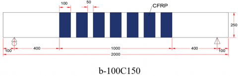
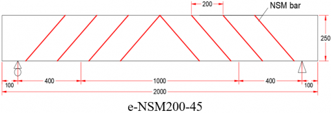
Figure 2. Details of strengthening of the beams
Table 6. Comparison between the experimental and numerical failure torque and angle of twist at failure
|
Beam's labeling |
Failure Torque (kN.m) |
(Tu)Exp/(Tu)FE |
Angle of Twist (degree/m) |
ѳExp/ ѳFE |
||
|
(Tu)Exp |
(Tu)FE |
ѳExp |
ѳFE |
|||
|
Control |
10.75 |
10.74 |
1.000931099 |
4.77 |
5.14 |
0.928015564 |
|
100C150 |
21.85 |
21.2 |
1.030660377 |
10.39 |
11.3 |
0.919469027 |
|
NSM200 |
14.35 |
14.1 |
1.017730496 |
3.47 |
4.22 |
0.822274882 |
|
Mean |
1.016 |
Mean |
0.89 |
|||
|
c.o.v |
1.466 |
c.o.v |
6.6 |
|||
Figure 3. Parts after assembly in ABAQUS for model
Figure 4. Isometric view of boundary condition for ends supports
Figure 5. Isometric view for meshing model for specimens
This part compares the results of the experiment with those from Askandar and Mahmood [18]. These consist of the relationship between the torque applied and the angle of twist, as well as the torque and angle of twist at the end of the process. Figure 6 illustrates how the experimental and numerical results for the three validation beams compare for the relationship between torque and angle of twist. Empirical evidence demonstrates that numerical models had a somewhat higher level of rigidity compared to experimental findings, in both the linear and non-linear realms, with a significant level of concurrence.
Table 6 compares the failure torque and twist angle retrieved from the finite element simulation to the experimental test at failure stage (located near failure torque) for all beams subjected to monotonic testing. The mean and standard deviation for the ratio of experimental ultimate torques to finite element ultimate torques (Tu) Exp /(Tu) FE were 1.016 and 1.466%, respectively. Similarly, for the ratio of experimental angle of twist to finite element angle of twist (Exp / FE), the mean and coefficient of variation were 0.89 and 6.6%. Thus, FE analysis is considered a dependable and preferred approach for modeling the nonlinear response of beams subjected to torsional impact, regardless of whether they are reinforced or not.
Figure 6. Experimental and numerical torque-angle of twist relation for the beams
Following the prior verification of the experimental results using finite element (FE) analysis, a comprehensive parametric analysis was performed utilizing the FE model. The selected variables in this study encompass the tilt of U-CFRP sheets or NSM bars, the impact of supplementary longitudinal CFRP or NSM reinforcement, the material composition of NSM bars, and the spacing between NSM bars. All beams possessed identical dimensions, including length, width, and height, as well as equivalent reinforcing and loading circumstances, as previously stated. Table 5 and Figure 2 show the details of parametric study beams.
5.1 Effect of inclination of U-CFRP sheets or NSM bars
Table 7 shows the maximum torque and twist corresponding angle of beams. The FE analysis results indicated that changing the inclination angle of the bar or sheet from 90 to 45º has a significant impact on the ultimate torque Tu, where the changing of the inclination angle from 90 to 45º increased the Tu by about (14.13, 13.39 and 13.83%) for beams with an inclination angle of 45º (100C150-45, NSM200-45and 100C150-45L) with respect to the similar beam for each one but with inclination angle of 90º. While changing the inclination angle of the bar or sheet from 90 to 45º has a varying effect on the angle of twist at failure ѳu, where the changing of the inclination angle from 90 to 45º increased the ѳu by about (20.4, 29 and 0.7%) for beams with an inclination angle of 45º (100C150-45, NSM200-45 and 100C150-45L) with respect to the similar beam for each one but with inclination angle of 90º. Figure 7 illustrates the impact of inclination on the torque-angle of twist relationship. The curves exhibit a linear behaviour until reaching the first cracking load. Subsequently, the curves display an inelastic response until failure occurs due to a decrease in torsional stiffness, resulting in a gradual increase in the twist angle. It is evident that altering the inclination angle of the bar or sheet from 90 to 45 degrees enhances the torsional stiffness of the beam.
Table 7. Effect of inclination on Tu and Ѳu
|
Beam-ID |
CFRP or Bar Spacing (mm) |
Inclination Angle of Bar or Sheet (Degree) |
Failure Torque Tu (kN.m) |
% of Increasing in Tu Because of Inclination |
Angle of Twist at Failure ѳu (Degree/m) |
% of Increasing in ѳu Because of Inclination |
|
100C150 |
150 |
90 |
21.288 |
- |
11.3 |
- |
|
NSM200 |
200 |
90 |
14.215 |
- |
4.27 |
- |
|
100C150L |
150 |
90 |
22.488 |
- |
15.2 |
- |
|
100C150-45 |
150 |
45 |
24.297 |
14.13 |
13.6 |
20.4 |
|
NSM200-45 |
200 |
45 |
16.118 |
13.39 |
5.51 |
29 |
|
100C150-45L |
150 |
45 |
25.599 |
13.83 |
15.3 |
0.7 |
Table 8. Effect of the additional longitudinal CFRP or NSM reinforcement on Tu and Ѳu
|
Beam-ID |
CFRP or Bar Spacing (mm) |
Additional Longitudinal Reinforcement Type |
Failure Torque Tu (kN.m) |
% of Increasing in Tu |
Angle of Twist at Failure ѳu (Degree/m) |
% of Increasing in ѳu |
|
100C150 |
150 |
- |
21.288 |
- |
11.3 |
- |
|
100C150-45 |
150 |
- |
24.297 |
- |
13.6 |
- |
|
NSM200 |
200 |
- |
14.215 |
- |
4.27 |
- |
|
100C150L |
150 |
CFRP-sheet |
22.488 |
5.6 |
15.2 |
34.5 |
|
100C150-45L |
150 |
CFRP-sheet |
25.599 |
5.4 |
15.3 |
11.1 |
|
NSM200L |
200 |
NSM-steel bar |
14.715 |
3.5 |
5.14 |
20.4 |
Figure 7. Effect of inclination on torque-angle of twist relation
5.2 Effect of the additional longitudinal CFRP or NSM reinforcement
Table 8 shows the maximum torque and twist corresponding angle of beams. The FE analysis results indicated that adding longitudinal CFRP or NSM reinforcement has a small impact on the ultimate torque Tu, where the adding longitudinal CFRP or NSM reinforcement increased the Tu by about (5.6, 5.4 and 3.5%) for beams with additional longitudinal CFRP or NSM reinforcement (100C150L, 100C150-45L, and NSM200L) with respect to the similar beam for each one but without additional longitudinal reinforcement. While adding longitudinal CFRP or NSM reinforcement has a bigger effect on the angle of twist at failure ѳu, where the adding longitudinal CFRP or NSM reinforcement increased the ѳu by about (34.5, 11.1 and 20.4%) for beams with additional longitudinal CFRP or NSM reinforcement (100C150L, 100C150-45L, and NSM200L) with respect to the similar beam for each one but without additional longitudinal reinforcement. Figure 8 shows the effect of adding longitudinal reinforcement on the torque-angle of twist relation, the curves indicate a linear relationship until the initial load that causes a crack. After that, the curves show a non-elastic response until the failure due to a loss of torsional stiffness. This caused the angle of twist to gradually increase. It's clear that adding longitudinal CFRP or NSM reinforcement increases the torsional and bending stiffness of the beam.
Figure 8. Effect of the additional longitudinal reinforcement on torque-angle of twist relation
5.3 Effect of the material type of NSM bars
Table 9 shows the maximum torque and twist corresponding angle of beams. The FE analysis results indicated that the material type of NSM bars has a varying effect on the ultimate torque Tu, where Tu increased by about (32, 32.7 and 42.4%) for beams with steel bars, GFRP bars, and CFRP bars with respect to the control beam (without NSM bars), which means that steel and GFRP gave approximately the same increasing percent while CFRP gave the large increasing percent in Tu. The impact of the material type of NSM bars on angle of twist at failure ѳu was small. Figure 9 demonstrates how the material type of the NSM bar affects the relationship between torque and angle of twist. The curves initially show a linear relationship until the first cracking load. After that, the curves exhibit an inelastic response until failure, caused by a decrease in torsional stiffness. This degradation gradually leads to an increase in the angle of twist. The beam reinforced with CFRP bars exhibits significant torsional rigidity.
Table 9. Effect of the material type of NSM bars on Tu and Ѳu
|
Beam-ID |
Material Type of NSM bars |
Failure Torque Tu (kN.m) |
% of Increasing in Tu |
Angle of twist at Failure ѳu (Degree/m) |
|
Control |
- |
10.767 |
- |
5.14 |
|
NSM200 |
Steel |
14.215 |
32 |
4.27 |
|
NSM200G |
GFRP |
14.29 |
32.7 |
5.142 |
|
NSM200C |
CFRP |
15.328 |
42.4 |
5.141 |
Table 10. Impact of the spacing of the NSM bars on Tu and Ѳu
|
Beam-ID |
NSM Bar Spacing (mm) |
Failure Torque Tu (kN.m) |
% of Increasing in Tu |
Angle of Twist at Failure ѳu (Degree/m) |
|
Control |
- |
10.767 |
- |
5.14 |
|
NSM200 |
200 |
14.215 |
32 |
4.27 |
|
NSM165 |
165 |
14.922 |
38.6 |
5.76 |
Figure 9. Effect of the material type of NSM bars on torque-angle of twist relation
5.4 Effect of the spacing of the NSM bars
Table 10 shows the maximum torque and twist corresponding angle of beams. The FE analysis results indicated that the spacing of NSM bars has a significant impact on the ultimate torque Tu, where Tu increased by about (32, and 38.6%) for beams with spacing of bars 200, and 165 mm with respect to the control beam (without NSM bars), which means that the spacing of NSM bars is inversely proportional to the ultimate torque. The influence of the spacing of NSM bars on the angle of twist at failure, represented by ѳu, was minimal. Figure 10 demonstrates how the spacing of NSM bars affects the torque-angle of twist relationship. The relationship between reducing the spacing of the NSM bars and the resulting increase in torsional and shear stiffness of the beam is evident.
Figure 10. Impact of the spacing of NSM bars on torque-angle of twist relation
5.5 Ultimate damage result of the numerical ABAQUS
Figure 11 shows a contour plot of the maximum plastic principal strain in the analyzed beams at the ultimate stage.
Figure 11. Ultimate damage result of the numerical ABAQUS
A strong correlation was observed between the ultimate torques and angle of twist of numerical models and those obtained through experimental means. Specifically, the mean and coefficient of variation for the ratio of the ultimate loads obtained from computational models to those obtained experimentally (Pu)FE/(Pu)Exp were discovered to be 1.016 and 1.466%, respectively. Similarly, for the deflection (δ FE / δ Exp), the mean value and coefficient of variation were determined to be 0.89 and 6.6%, respectively.
Changing the inclination angle of the bar or sheet from 90 to 45º has a significant effect on the maximum torque Tu, where the changing of the inclination angle from 90 to 45º increased the Tu by about (14.13, 13.39 and 13.83%) for beams with an inclination angle of 45º (with CFRP sheets spacing of 150 mm, with NSM bars spacing of 200 mm, and with CFRP sheets spacing of 150 mm and longitudinal CFRP sheet) with respect to the similar beam for each one but with inclination angle of 90º. Which means that changing the inclination angle of the bar or sheet from 90 to 45º increases the torsional stiffness of the beam. This result supports the finding of Chalioris [8].
Changing the inclination angle of the bar or sheet from 90 to 45º has a varying effect on the angle of twist at failure ѳu, where the changing of the inclination angle from 90 to 45º increased the ѳu by about (20.4, 29 and 0.7%) for beams with an inclination angle of 45º (with CFRP sheets spacing of 150 mm, with NSM bars spacing of 200 mm, and with CFRP sheets spacing of 150 mm and longitudinal CFRP sheet) with respect to the similar beam for each one but with inclination angle of 90º.
Regarding the torque-angle of twist relationships, the curves show a linear behavior relationship until the first cracking load, then the curves show an inelastic response until the failure due to degradation in torsional stiffness; which led gradually to an increase in the angle of the twist.
Adding longitudinal CFRP or NSM reinforcement has a small impact on the ultimate torque Tu, where the adding longitudinal CFRP or NSM reinforcement increased the Tu by about (5.6, 5.4 and 3.5%) for beams with additional longitudinal CFRP or NSM reinforcement (100C150L, 100C150-45L, and NSM200L) with respect to the similar beam for each one but without additional longitudinal reinforcement. It's clear that adding longitudinal CFRP or NSM reinforcement increases the torsional and bending stiffness of the beam.
Adding longitudinal CFRP or NSM reinforcement has a bigger effect on the angle of twist at failure ѳu, where the adding longitudinal CFRP or NSM reinforcement increased the ѳu by about (34.5, 11.1 and 20.4%) for beams with additional longitudinal CFRP or NSM reinforcement (100C150L, 100C150-45L, and NSM200L) with respect to the similar beam for each one but without additional longitudinal reinforcement.
The material type of NSM bars has a varying effect on the ultimate torque Tu, where Tu increased by about (32, 32.7 and 42.4%) for beams with steel bars, GFRP bars, and CFRP bars with respect to the control beam (without NSM bars), which means that steel and GFRP gave approximately the same increasing percent while CFRP gave the large increasing percent in Tu. The impact of the material type of NSM bars on angle of twist at Failure ѳu was small.
The spacing of NSM bars has a significant impact on the ultimate torque Tu, where Tu increased by about (32, and 38.6%) for beams with spacing of bars 200, and 165 mm with respect to the control beam (without NSM bars), which means that the spacing of NSM bars is inversely proportional to the ultimate torque. The impact of the spacing of NSM bars on angle of twist at Failure ѳu was small. It's clear that reducing the spacing of the NSM bars increases the torsional and shear stiffness of the beam.
Studying the torsional performance of reinforced concrete beams strengthened with CFRP strips under repeated or cyclic loads.
Studying the torsional performance of reinforced concrete beams with partially pre-stressed and strengthened with CFRP bars.
The authors highly appreciate the support offered by civil engineering department college of engineering Tikrit University. Special thanks and gratitude Erbil Concrete Laboratory ECL for their guidance and orientation.
[1] Panchacharam, S., Belarbi, A. (2002). Torsional behavior of reinforced concrete beams strengthened with FRP composites. In First FIB Congress, Osaka, Japan, pp. 1-110.
[2] Amiri, J.V., ALibygie, M.H. (2004). Effect of small circular opening on the shear and flexural behavior and ultimate strength of reinforced concrete beams using normal and high strength concrete. In Proceedings of the 13th World Conference on Earthquake Engineering, Vancouver, BC, Canada, pp. 1-14.
[3] Abdul Jabbar Hassan, M., Izzet, A.F. (2021). Finite element modeling of RC gable roof beams with openings of different sizes and configurations. Mechanics of Advanced Materials and Structures, 28(15): 1604-1620. https://doi.org/10.1080/15376494.2019.1697470
[4] Madkour, H., Ahmed, K. (2007). Three-dimensional modelling for reinforced concrete beams with openings based on nonlinear elastic-damage theory. JES. Journal of Engineering Sciences, 35(1): 9-27. https://doi.org/10.21608/JESAUN.2007.111370
[5] Askandar, N.H., Mahmood, A.D., Kurda, R. (2022). Behaviour of RC beams strengthened with FRP strips under combined action of torsion and bending. European Journal of Environmental and Civil Engineering, 26(9): 4263-4279. https://doi.org/10.1080/19648189.2020.1847690
[6] Shanmugasundaram, S., Mohanraj, R., Senthilkumar, S., Padmapoorani, P. (2022). Torsional performance of reinforced concrete beam with carbon fiber and aramid fiber laminates. Revista de la Construcción, 21(2): 329-337. https://doi.org/10.7764/rdlc.21.2.329
[7] ABAQUS/Standard, Ver. (2019). User’s Manual, Hibbitt, Karlson and Sorensen, Inc, Johnston, Rhode Island, United States.
[8] Chalioris, C.E. (2007). Tests and analysis of reinforced concrete beams under torsion retrofitted with FRP strips. WIT Transactions on Modelling and Simulation, 46: 1-10. https://doi.org/10.2495/CMEM070631
[9] Jariwala, V.H., Patel, P.V., Purohit, S.P. (2013). Strengthening of RC beams subjected to combined torsion and bending with GFRP composites. Procedia Engineering, 51: 282-289. https://doi.org/10.1016/j.proeng.2013.01.038
[10] Majeed, A.A., Allawi, A.A., Chai, K.H., Badaruzzam, H.W. (2017). Behavior of CFRP strengthened RC multicell box girders under torsion. Structural Engineering and Mechanics, 61(3): 397-406. https://doi.org/10.12989/sem.2017.61.3.397
[11] Tibhe, S.B., Rathi, V.R. (2016). Comparative experimental study on torsional behavior of RC beam using CFRP and GFRP fabric wrapping. Procedia Technology, 24: 140-147. https://doi.org/10.1016/j.protcy.2016.05.020
[12] Alabdulhady, M.Y., Sneed, L.H., Abdelkarim, O.I., ElGawady, M.A. (2017). Finite element study on the behavior of RC beams strengthened with PBO-FRCM composite under torsion. Composite Structures, 179: 326-339. https://doi.org/10.1016/j.compstruct.2017.07.079
[13] Al-Bayati, G., Al-Mahaidi, R., Hashemi, M.J., Kalfat, R. (2018). Torsional strengthening of RC beams using NSM CFRP rope and innovative adhesives. Composite Structures, 187: 190-202. https://doi.org/10.1016/j.compstruct.2017.12.016
[14] Abdulhameed, A.A., Hanoon, A.N., Abdulhameed, H.A., Mohaisen, S.K. (2019). Energy absorption evaluation of CFRP-strengthened two-spans reinforced concrete beams under pure torsion. Civil Engineering Journal, 5(9): 204301191. https://doi.org/10.28991/cej-2019-03091389
[15] Al-Rousan, R., Abo-Msamh, I. (2020). Impact of anchored CFRP on the torsional and bending behaviour of RC beams. Magazine of Civil Engineering, 4 (96): 79-93.
[16] Ali, S.A., Ahmed, F.H. (2022). Performance of strengthened RC beams with torsional CFRP wraps in monolithic framed structures: Experimental and numerical investigation. In Structures, 46: 936-954. https://doi.org/10.1016/j.istruc.2022.10.122
[17] Elwakkad, N.Y. (2023). Numerical study on the torsional behavior of CFRP-strengthened RC beams. Global Journal of Engineering and Technology Advances, 17(2): 12-30. https://doi.org/10.30574/gjeta.2023.17.2.0228
[18] Askandar, N., Mahmood, A. (2019). Comparative investigation on torsional behaviour of RC beam strengthened with CFRP fabric wrapping and near-surface mounted (NSM) steel bar. Advances in Civil Engineering, 2019: 1-15. https://doi.org/10.1155/2019/9061703
[19] Abdel-kareem, A.H., Debaiky, A.S., Makhlouf, M.H., Badwi, M. (2019). Repairing and strengthening of RC beams using thin lower concrete layer reinforced by FRP bars. Technology, 10(2): 1949-1966.