Marwa M. Ismaeel*![]() | Anwaar A. Al-Dergazly
| Anwaar A. Al-Dergazly![]() | Khider Al-Jaburi
| Khider Al-Jaburi![]() | Samah K. AbdulKareem
| Samah K. AbdulKareem![]()
© 2024 The authors. This article is published by IIETA and is licensed under the CC BY 4.0 license (http://creativecommons.org/licenses/by/4.0/).
OPEN ACCESS
This study examined the compatibility of an orthopedic implant made from polyamide 12 sintering, coupled with a composite made from Ti6Al4V/ST316L laser fusion, both in vitro and in vivo. SLM 3D printing was used to construct the composite implant of Ti6Al4V/ST316L, while SLS 3D printing was used for the polyamide 12 implant. SEM analysis, X-ray diffraction analysis, and energy dispersive spectroscopy (EDS) were used to characterize the fabricated implants. Mechanical properties of the implants were evaluated using a universal testing machine. Using finite element modeling, von Mises stresses within implants and human bones could be examined. It involved increasing the cell count and implanting MC3T3-E1 preosteoclasts on implants for a week. Biocompatibility was determined using an AlamarBlue® fluorescence test. After six weeks of implantation, rabbit femurs were stained with Hematoxylin and Eosin to determine in vivo biocompatibility of the implant. Based on the findings, both the polyamide 12 implant and the Ti6Al4V/ST316L composite SLM-3D printed by SLS-3D printing were biocompatible. Finite element analysis revealed that the maximum Von Misses stress was within acceptable limits.
Selective Laser Melting (SLM), Polyamide 12, Selective Laser Sintering (SLS), Ti6Al4V, ST316L
One of the common degenerative joint disease in human body is knee osteoarthritis [1]. The gold standard for the treatment of knee osteoarthritis is total knee arthroplasty [2]. Femoral components, tibial components, and tibial trays are three components that make up artificial knee implants. Knee joint prosthetics have been traditionally manufactured by CNC, CAD-driven machining, or powder metallurgy (PM) manufacturing processes, using wrought or cast bar stock [3-5]. These fabrication methods, despite their advancements, lack flexibility. For patients whose anatomy deviates from the norm, these technologies cannot accurately control implant shape and structure [6]. Currently, additive manufacturing technology is extensively used for fabrication of orthopedic implants with controlled shape and internal structure [7]. Metal alloys have been explored for the fabrication of femoral and tibial components of knee prosthesis [8]. The most commonly used metals are Ti6Al4V, and Stainless steel alloys. The major advantages of these metallic biomaterials are their corrosion resistance, ease of availability, and biocompatibility [9, 10]. However, the higher Young’s modulus of these metallic biomaterials in comparison with human cortical bone causes stress shielding and hampers their use in orthopedic implants [11]. SLM as an additive manufacturing method is commonly used for manufacturing metal structures [12]. The physical and mechanical properties of these structures can be controlled by SLM process parameters such as laser power, hatch distance, and laser speed [13]. Polymeric biomaterials such as polymethylmethacrylate, polyethylene, and silicon rubber are mainly used as “inserts” for orthopedic implants [14]. Polyamide 12 is a cost effective polymer with advantages such as resistance to corrosion and chemical degradation [15, 16]. SLS is an additive manufacturing process for manufacturing polymeric components [17, 18]. However, the feasibility of SLS printed polyamide 12 as a tibial tray for knee prosthesis have not been studied yet. In this study we 3D-printed Ti6Al4V/ST316L composite implants by SLM process and polyamide 12 implants by SLS process. Physical and mechanical characterization were done. Von Mises stress distribution and magnitude in femur and tibia bones, femoral and tibial inserts, and tibial tray were analyzed by finite element modeling. The in vitro and in vivo biocompatibility of Ti6Al4V/ST316L composite implants and polyamide 12 implants was evaluated.
2.1 SLM 3D-printing of Ti6Al4V/ST316L
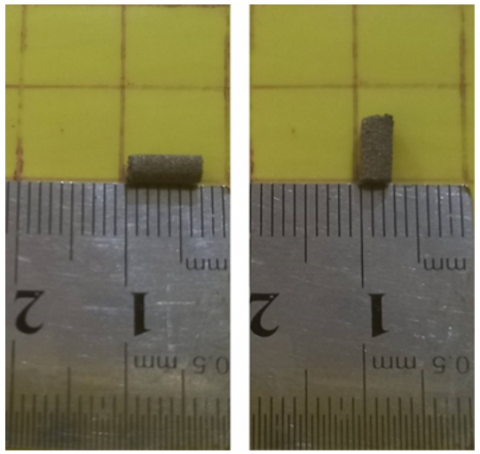
Aconity GmbH based in Herzogenrath, Germany developed Aconity 3D MIDI, a product used to create the implant (see Figure 1). In this process, a laser source with a wavelength of 1070 nm and a maximum power output of 100 W was used. There were variations in the diameter of the spot from 80mm to 500mm. Workspaces were cylindrical, standing 170 mm high and 150 mm wide. Argon gas, known for its inert qualities, was used during the fabrication process. Two vital functions were served by this gas, which circulated at a rate of 7 liters per minute. A less chemically reactive environment initially prevented corrosion. It also prevented contamination or oxidation of the powder used in the process. The implants were printed using SLM as outlined in Table 1.
Figure 1. 3D view of SLM processed Ti6Al4V/ST316L (75/25 wt%) implants
Table 1. Three-dimensional printing parameters by SLM
|
# |
Laser Power (W) |
Hatch Distance (mm) |
Laser Speed (mm/s) |
ST316L wt% |
|
1 |
90 |
0.11 |
300 |
25 |
|
2 |
90 |
0.11 |
300 |
50 |
|
3 |
90 |
0.11 |
300 |
0 |
|
4 |
90 |
0.11 |
500 |
25 |
|
5 |
90 |
0.11 |
100 |
25 |
|
6 |
90 |
0.14 |
300 |
25 |
|
7 |
90 |
0.08 |
300 |
25 |
|
8 |
100 |
0.11 |
300 |
25 |
|
9 |
80 |
0.11 |
300 |
25 |
2.2 SLS 3D-printing of polyamide 12
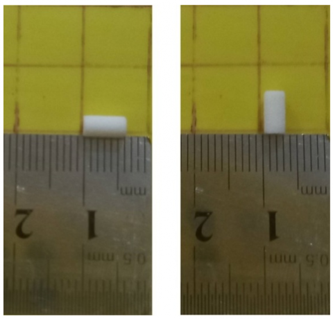
Polyamide 12 insets (Figure 2) are made using SLS 3D printer. This machine has been made by iDesign 3dprinter Company with brand T1 R230 Pro. Polyamide 12 material with biocompatible properties is used. The layer thickness is 120 microns and the power of laser is 16 W. Also, the laser speed and the distance between the lines are equal to 1600 mm/s and 0.250 mm respectively.
Figure 2. 3D view of SLS processed polyamide 12 inset
2.3 Properties of mechanical systems
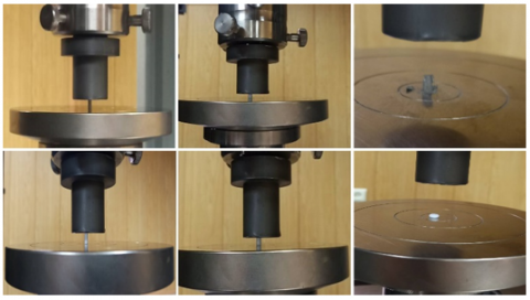
Aconity GmbH, based in Herzogenrath, Germany, produces the Aconity 3D MIDI system that was used to create the implant (referenced in Figure 3). With a wavelength of 1070 nm, the laser source has a maximum power capacity of 100 W. The spot diameter of the laser source varies from 80 to 500 μm. With a maximum height of 170 mm and a maximum width of 150 mm, the laser source occupies a cylindrical workspace. During manufacturing, argon gas was used because of its inert properties. Approximately 7 liters of gas were circulated per minute, serving two purposes. As a result, corrosion was reduced as a result of a less conducive environment. Secondly, the powder was prevented from becoming contaminated or oxidized. As outlined in Table 1, the implants were 3D printed using SLM [19].
Figure 3. Compression test setup
2.4 Composition of the elements
Utilizing EDS; Zeiss, Oberkochen, Germany, the 3D-printed Ti6Al4V/ST316L implant's fundamental components were examined. In order to ensure accuracy, the implants were evaluated by three independent laboratories.
2.5 Crystalline phases
The use of X-ray diffraction allowed identification of crystalline phases tucked within the composite structure. A Philips PW1730 X-ray diffractometer located in Amsterdam, Netherlands, was used for this process. During this operation, the parameters were set as follows: step size was set at 0.05°, time allocated per step was 1 second, voltage was set at 40 kV, and current was set at 30mA. A crystalline phase detection was achieved using Malvern Panalytical Ltd's XPert High Score Plus software, which is a product of Malvern Panalytical Ltd. The Scherrer equation was used to determine the dimensions of crystallites within the particles (D = (κλ)/(β.cos(θ)). In this particular equation, "D" is representative of the crystal size while "λ" denotes the X-ray wavelength of Cu-Kα radiation and is equivalent to 1.54Å. It represents a Bragg angle within the range of 10–80°. "β" is the full width at half maximum in radians, and "κ" is crystallite shape factor, which was set to 0.9.
2.6 A topographic and morphological analysis of the surface
Through scanning electron microscopy, 3D printed implants were examined for their shape and configuration. A Burgess Hill, UK-based Edwards sputter coater S150B was used to coat the implants with gold. An electron microscope, the Zeiss EVO LS-15, a product of Zeiss, Oberkochen, Germany, was used to examine them with an acceleration voltage set at 20. Kilovolts were used to create the images.
2.7 In vitro biocompatibility
Incubators at the American Type Culture Collection, Manassas, VA, USA, contained 5% CO2 and maintained 37℃ to create a moist environment. Gibco, Life Technologies, Waltham, MA, USA and Sigma-Aldrich®, St. Louis, MO, USA provided 10% fetal bovine serum (FBS) and 1% PSF (antibiotic antimycotic solution). Cell separation at 37℃ was performed using ethylenediaminetetraacetic acid and trypsin from Invitrogen, Waltham, MA, USA. Following the separation of the cells, 10% FBS and 1% PSF was added to the medium. On a 24-well culture plate, five droplets of cell suspension (10 l each) were evenly distributed on the implant surface. During three hours of incubation at 37℃ with 5% CO2, cells were incubated to facilitate adherence to implant seeds. The osteogenic medium was added every half hour during this prolonged period to prevent evaporation. In the same medium, the implants were seeded and cultured for seven days after being seeded in osteogenic medium (1500 l/well). Every two days, modifications were made to this process. To assess MC3T3-E1 pre-osteoblast proliferation, AlamarBlue® fluorescent assay was used to determine the number of cells in scaffolds at days 1, 3, and 7 and divide the number by the number of cells in implants at day 1. Throughout the study, implants were transferred from one plate to another, AlamarBlue® was added, and the fluorescence was measured at each time point. Incubation at 37℃ in a humidified incubator with 5% CO2 followed by two washings with PBS was performed after the AlamarBlue® assay on each day. Three implants were used in three independent experiments (n = 3) to obtain data [20].
2.8 In vivo biocompatibility
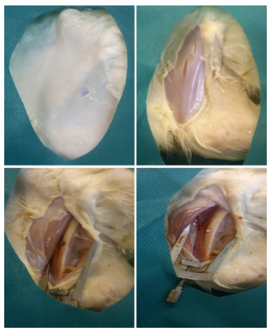
Mississippi State University strictly followed the Guide for the Care and Use of Laboratory Animals (Protocol #04–017) in their animal care and usage procedures. Each beast was given intramuscular injections of ketamine (10 mg/kg), midazolam (0.1 mg/kg), and buprenorphine (0.015 mg/kg) during the process. An oxygen mask supplied isoflurane to sustain anesthesia post endotracheal intubation. In sterilized surgical processes, a limb from each creature, either right or left, was randomly removed. Cutting through all the layers of soft tissue in the upper anterior section of the femur was the first step. The twist drill within the drill sleeve was then used to drill four guide holes to ensure a standardized positioning. To avoid tissue overheating, copious irrigation with sterile saline was performed during site preparation. Manual pressure was utilized for pin insertion into each hole until it was level with the cortex (Figure 4). Each rabbit received an implant based on a random allocation of holes. Sutures of 4-0 size were then used to stitch the implantation area together. As soon as the animals recovered from surgery, they were closely monitored.
Figure 4. Animal surgical and implantation procedure
2.9 Eosin staining and Hematoxylin
An analysis of the implanted femoral site was performed using Hematoxylin and Eosin staining. Fixing the bone samples in formaldehyde solution was necessary for staining them with H&E. In order to decalcify fixed bone samples, the EDTA solution was applied. After making the paraffin blocks, the sections of 5 m were stained with H&E. Nikon TE2000 U; Nikon Corporation) light microscope was used for optical imaging.
2.10 Finite element (FE) modeling
2.10.1 Model designs
MRI images were used to develop the geometric designs of implants and bones using CATIA software. Finite element (FE) modeling was then performed using the Abacus software. It was assumed that both the tibia and femur inserts had achieved full osteointegration and were securely bonded to their respective bones.
2.10.2 Boundary conditions
Static compressive load in the “y’’ direction with the magnitude of F y = 2667 N was applied on the femur section. The apical part of tibia bone was fixed, allowing the rotation around X-axis, Y-axis, and Z-axis.
2.10.3 Finite-element mesh
Triangular structure meshes on all components were generated using Hypermesh v14.0 software (Altair Engineering, Troy, MI, USA). The contact between the femoral and tibial bones and the insert was defined as forced zero-displacement frozen contact. The sensitivity of the network was examined to achieve high quality results. To obtain accurate numerical results, mesh convergence studies were performed using adaptive elements with sizes ranging from 0.8 to 2 mm.
2.10.4 Material properties
The epiphyses of the femur and tibia were analyzed. The bone properties of both the femur and tibia were assumed to be isotropic and homogeneous.
3.1 Topography of the surface
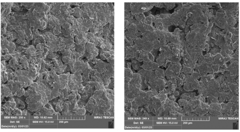
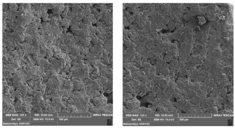
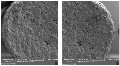
SEM images show the surface topography of the implant. According to Figure 5, the implant has surface irregularities with a surface topology with small peaks and valleys, suggesting that the implant surface influences protein adsorption and cell behavior [21]. Surfaces with micron-level roughness have been found to enhance cell adhesion, viability, and osteogenic differentiation [22, 23]. Our implant surfaces possess a roughness that falls within the micrometer range. Consequently, these implants might facilitate in vitro cell adhesion, viability, and osteogenic differentiation, similar to the observations made with titanium having increased surface roughness [24]. Prior to cells sticking to biomaterial surfaces, proteins get absorbed from body fluids, controlling subsequent cell adhesion and behavior. This is predictable as surface roughness is known to encourage protein absorption [25]. Given that protein absorption on surfaces aids in cell proliferation and osteogenic differentiation [26], enhanced cell proliferation and osteogenic activity on surfaces are linked with improved protein absorption, which is an outcome of a rough surface topography. The possibility of this has been proposed.
Figure 5. SEM images of the Ti6Al4V/ST316L and polyamide 12 implants
3.2 Elemental composition
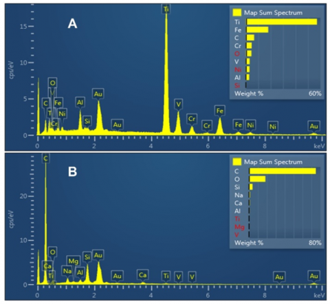
Upon examination of the EDS micrograph in Figure 6a, Ti6Al4V and ST316L are identified within the implant's elemental composition. The elements are evenly distributed throughout the implant structure [27, 28]. There are 20.94% carbon, 10.45% oxygen, 3.69% aluminium, 0.36% silicon, 44.89% titanium, 2.26% vanadium, 3.41% chromium, 12.11% iron, and 1.89% nickel in the structure. Based on the EDS micrograph shown in Figure 6b, polyamide 12 is present in the elemental composition. This structure has the following proportions: Carbon: 74.78%, Oxygen: 18.3%, Sodium: 1.06%, Magnesium: 0.18%, Aluminium: 0.55%, Silicon: 3.94%, Calcium: 0.76%, Titanium: 0.44%.
Figure 6. EDC micrograph: a) Ti6Al4V/ST316L; and b) polyamide 12 implant
3.3 Phase identification with XRD micrograph
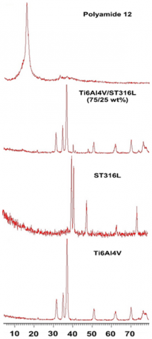
X-ray diffraction (XRD) analysis was used to identify the phases of SLM Ti6Al4V/ST316L, Ti6Al4V powder, ST316L powder, and polyamide 12 (see Figure 7). These phases were analyzed and identified using XRD analysis. His XRD diffraction peak of Ti6Al4V was detected at 40°, indicating the presence of a peak corresponding to the structure of Ti6Al4V. Furthermore, the peak at 53° matched the structure of ST316L [23, 24]. The XRD diffraction peak of polyamide 12 was detected at 21°, indicating the presence of a peak corresponding to the structure of polyamide 12.
Figure 7. An XRD micrograph of titanium alloy 6al4v, stainless steel 316l, and titanium alloy 6al4v/steel 316l implants
3.4 In vitro biocompatibility
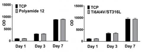
Materials such as titanium, steel, and polymer are commonly used in the production of medical equipment. There is a surge in the production of knee and hip joint replacement devices in the medical industry as well as novel orthopedic tools. Globally, titanium alloy (Ti-6Al-4V), steel (ST316L), and polyamide 12 are recognized and produced as essential elements for joint replacement medical devices. Nevertheless, local conditions and manufacturing facilities can affect the biocompatibility of these materials. The purpose of this study was to evaluate the biocompatibility of these materials. MC3T3-E1 preosteoclast proliferation was increased when place on a Ti6Al4V/ST316L composite implant (1.07-fold, p<0.05, day 1; 1.03-fold, p<0.005, day 3; 1.2-fold, p<0.05, day 7) compared to those on Ti6Al4V implants (Figure 8). Ti6Al4V implants had a cell viability rate of 91.7±0.6%. A significant increase in viability was seen with Ti6Al4V/ST316L implants (Figure 9). Ti6Al4V/ST316L implants have an enhanced wettability surface compared to Ti6Al4V implants, which may explain the enhanced proliferation and viability. Proteins are adsorbed to the surface of cells prior to attachment [28].
Figure 8. Cell proliferation on Ti6Al4V/ST316L and polyamide 12 implants
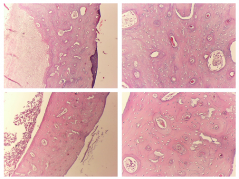
Figure 9. A comparison between Ti6Al4V/ST316L and polyamide 12 implants implanted into rabbit femurs
3.5 In vivo biocompatibility
A six-week period following the implantation of Ti6Al4V/ST316L and polyamide 12 implants into rabbit femurs, bone tissue surrounding the implantation areas was collected and stained with H&E (as shown in Figure 9). Cell membranes and nuclei were found to be unharmed in the H&E stained samples. Tissues at the implanted sites showed no signs of inflammatory cell infiltration. Osteolysis and bone degradation were also absent. Blood vessels, osteoblasts, and osteocytes remained in place. Cross-sections of the bone showed that it was healthy and free of pathological changes.
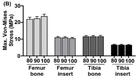
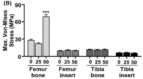
3.6 An analysis of laser power's effect on von Mises stress distribution and magnitude
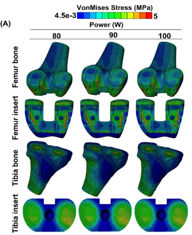
Within SLM 3D printing, the finite element method was used to investigate how laser power impacts von Mises stress distribution and intensity. The laser power for this evaluation was 80, 90, and 100 W, as illustrated in Figure 10. Using a laser with a velocity of 300 mm/s and a ST316L composition of 25 percent by weight, the hatch spacing was 0.11 mm. There was a maximum von Mises stress intensity of 22-26 MPa for the femur bone, 11-13 MPa for the tibia bone, 10-12 MPa for the femoral insert, and 6-7 MPa for the tibial insert for various components. In all of the implants tested, the maximum von Mises stress never exceeded the yield stress of the bulk material, indicating stability within the body after application of load. Femurs and tibias also had lower von Mises stresses than human cortical bones. During the SLM 3D printing process, variations in power did not significantly influence peak von Mises stress intensity in implants.
Figure 10. At hatch distance: 0.11 mm, laser speed: 300 mm/s, and 25% ST316L percentage, SLM process power affects (A) the von Mises stress distribution for the femur bones, femur inserts, tibia bones and tibia inserts, and (B) the maximum von Mises stress magnitude of the femur bones, femur inserts, tibia bones, and tibia inserts
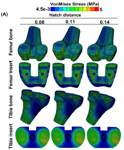
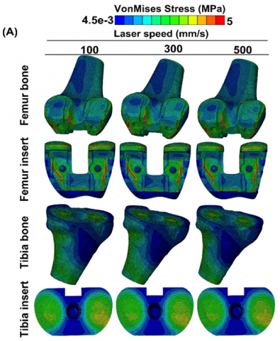
3.7 Distribution and magnitude of von Mises stress with hatch distance
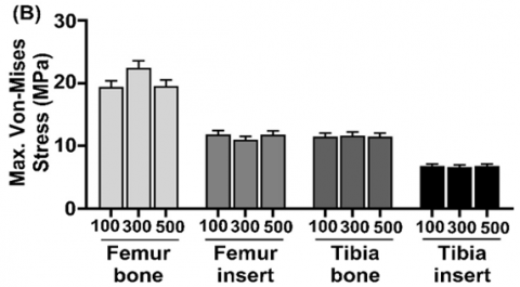
The influence of hatch spacing in SLM 3D printing on the distribution and magnitude of von Mises stress is shown for hatch spacing: 0.08, 0.11, and 0.14 mm, laser power: 90 W, laser speed: 300 mm/s, and finite element in ST316L. Determined by analysis. Analysis weight%: 25 wt% (Figure 11). Maximum Mises stress in femur: 21-27 MPa, tibial bone: 11-13 MPa, femoral insert: 9-12 MPa, tibial insert: 6-7 MPa. Von Mises stresses for all implants were below the bulk material's yield strength. The implant remains stable within the body even when loaded [25]. Human cortical bone's yield strength was not exceeded by maximum von Mises stresses in femur and tibia [26]. The maximum von Mises stress of the implant did not change significantly as the hatch spacing was changed in the SLM 3D printing process.
Figure 11. Effect of SLM process hatch distance on (A) von Mises stress distribution of femur bone, femur insert, tibia bone and tibia insert, and (B) maximum von Mises stress magnitude of femur bone, femur insert, tibia bone and tibia insert at power: 90 W, laser speed: 300 mm/s, and ST316L percentage of 25%
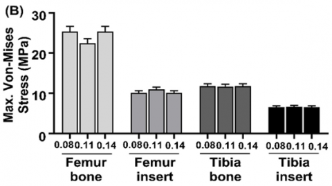
3.8 Laser speed and its effect on von Mises stress distribution and magnitude
Different laser velocities were tested in Selective Laser Melting (SLM) 3D printing with different laser powers, hatch spacings, and finite elements in ST316L and different laser velocities for the spread and intensity of von Mises stress. A comprehensive assessment establishes this. According to Figure 12, 25 wt% is the weight analysis. Femur mises stress ranges from 18-24 MPa, tibia mises stress ranges from 10-13 MPa, femoral insert mises stress ranges from 10-13 MPa, and tibial insert mises stress ranges from 6-8 MPa. In all the implants, the peak von Mises stress was not greater than the raw material's yield strength. Implants remain stable under bodily pressure as a result of this. Bones from the femur and tibia did not exceed the yield strength of cortical bone when subjected to von Mises stress. Peak von Mises stress of the implant was not significantly impacted by modifying the laser velocity during SLM 3D printing.
Figure 12. Effect of SLM process laser velocity on (A) von Mises stress distribution of femur bone, femur insert, tibia bone and tibia insert, and (B) maximum von Mises stress magnitude of femur bone, femur insert, tibia bone and tibia insert at power: 90 W, hatch distance: 0.11 mm, and ST316L percentage of 25%
3.9 Effect of ST316L wt% on von Mises stress distribution and magnitude
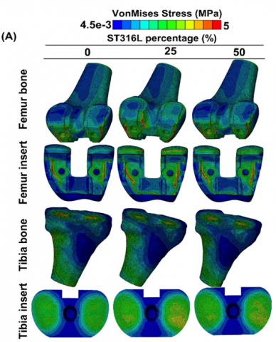
Based on ST316L weight percentage and laser power: 90 W, laser speed: 300 mm/s, and hatch distance: 0.11 mm, the effect of von Mises stress distribution and magnitude was analyzed by finite element analysis (Figure 13). In terms of Von Mises stress magnitude, the femur bone reaches 21-75 MPa, the tibia bone reaches 11-13 MPa, the femoral insert reaches 9-12 MPa, and the tibial insert reaches 5-7 MPa. As a result, all implants were stable in the body under loading since their von Mises stress did not exceed their yield stress. Human cortical bone yield stress did not exceed von Mises stress in femur and tibia bones. Compared to 0 wt% and 25 wt% ST316L, the change in ST316L wt% in SLM process significantly changes the femur's maximum von Mises stress.
Figure 13. Effect of ST316L percentage on (A) von Mises stress distribution of femur bone, femur insert, tibia bone and tibia insert, and (B) maximum von Mises stress magnitude of femur bone, femur insert, tibia bone and tibia insert at power: 90 W, hatch distance: 0.11 mm, and laser velocity: 300 mm/s
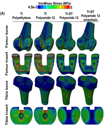
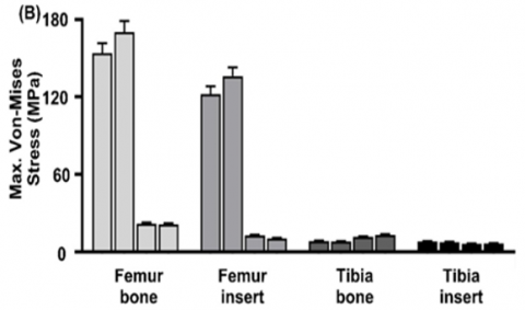
In Figure 14, maximum von Mises stress of whole model was 153.9 MPa for commercial prosthesis, it was 170.3 MPa for total prosthesis with commercial insert and polyamide as plastic part. The maximum von Mises stress decreased to 21.3 MPa for Ti6Al4V/ST316L insert and polyamide 12 insert. This maximum von Mises stress decreases to 21.09 MPa when the polyamide 12 is anisotropic. Maximum von Mises stress of femoral insert was 122.2 MPa for commercial prosthesis, it was 136.1 MPa for femoral insert with commercial insert and polyamide as plastic part. The maximum von Mises stress decreased to 12.67 MPa for Ti6Al4V/ST316L insert and polyamide 12 insert. This maximum von Mises stress decreases to 10.42 MPa when the polyamide 12 is anisotropic. Maximum von Mises stress of tibia insert was 7.98 MPa for commercial prosthesis, it was 7.461 MPa for tibia insert with commercial insert and polyamide as plastic part. The maximum von Mises stress decreased to 6.216 MPa for Ti6Al4V/ST316L insert and polyamide 12 insert. This maximum von Mises stress increased to 6.53 MPa when the polyamide 12 is anisotropic. Maximum von Mises stress of whole model was 153.9 MPa for commercial prosthesis, it was 170.3 MPa for total prosthesis with commercial insert and polyamide as plastic part. The maximum von Mises stress decreased to 21.3 MPa for Ti6Al4V/ST316L insert and polyamide 12 insert. This maximum von Mises stress decreases to 21.09 MPa when the polyamide 12 is anisotropic. Maximum von Mises stress of plastic insert was 6.8 MPa for commercial prosthesis, it was 7.636 MPa for plastic insert with commercial insert and polyamide as plastic part. The maximum von Mises stress decreased to 14.91 MPa for Ti6Al4V/ST316L insert and polyamide 12 insert. This maximum von Mises stress increased to 18.56 MPa when the polyamide 12 is anisotropic.
Figure 14. Von Mises stress distribution and magnitude of femur bone, femur insert, tibia bone and tibia insert in commercial Ti/polyethylene, Ti/Polyamide 12, Ti-St/Polyamide 12, and Ti-ST/polyamide 12 anisotropic
In conclusion, SLM 3D-printed Ti6Al4V/ST316L composite implants and SLS 3D-printed polyamide 12 implants can be as a good candidate for total knee arthroplasty prosthesis. The presented results establish a correlation between the SLM process parameters and the resulting mechanical properties of Ti6Al4V/ ST316L specimens. Optimizing TKA model by controlling the biomechanical stresses distributed within its both components and supporting bones is a valid approach to achieving favorable long-term outcomes. The 3D finite-element analysis provides an effective pre-operative method for planning patient-specific TKA prostheses, and for designing future models that preserves the biomechanical function of the Femur-TKA-Tibia system. Biocompatible materials are essential for development of medical devices. In recent years human tissues, such as knee and hip replacements, have been artificially produced by biocompatible materials. Titanium alloy Ti-6Al-4V, Steel (ST316L), and Polyamide 12 are popular materials for these applications. This study evaluated the biocompatibility of Ti-6Al-4V titanium alloy Steel (ST316L), and Polyamide 12 according to ISO 10993. Our results confirm that all materials are biocompatible materials and thus suitable for medical devices.
[1] Campanelli, L.C. (2021). A review on the recent advances concerning the fatigue performance of titanium alloys for orthopedic applications. Journal of Materials Research, 36: 151-165. https://doi.org/10.1557/s43578-020-00087-0
[2] Quilez, M.P., Seral, B., Pérez, M.A. (2017). Biomechanical evaluation of tibial bone adaptation after revision total knee arthroplasty: A comparison of different implant systems. Plos One, 12(9): e0184361. https://doi.org/10.1371/journal.pone.0184361
[3] Liu, Y., Chen, B.P., Wang, C.Y., Chen, H., Zhang, A.B., Yin, W.H., Wu, N.C., Han, Q., Wang, J.C. (2021). Design of porous metal block augmentation to treat tibial bone defects in total knee arthroplasty based on topology optimization. Frontiers in Bioengineering and Biotechnology, 9: 765438. https://doi.org/10.3389/fbioe.2021.765438
[4] Peto, M., Ramírez-Cedillo, E., Hernández, A., Siller, H.R. (2019). Structural design optimization of knee replacement implants for additive manufacturing. Procedia Manufacturing, 34: 574-583. https://doi.org/10.1016/j.promfg.2019.06.222
[5] Bargir, M.A., Phafat, N.G., Sonkamble, V. (2023). A review of artificial knee joint by additive manufacturing technology to study biomechanical characteristics. Advances in Oral and Maxillofacial Surgery, 100447. https://doi.org/10.1016/j.adoms.2023.100447
[6] Doloi, S., Rajput, A.S., Kapil, S., Das, M. (2023). Hybrid additive manufacturing of knee joint implant: Possibilities and challenges. In: Ramesh Babu, N., Kumar, S., Thyla, P.R., Sripriyan, K. (eds) Advances in Additive Manufacturing and Metal Joining. Lecture Notes in Mechanical Engineering. Springer, Singapore. pp. 161-176. https://doi.org/10.1007/978-981-19-7612-4_14
[7] Singla, A.K., Banerjee, M., Sharma, A., Singh, J., Bansal, A., Gupta, M.K., Shahi, A.S., Khanna, N., Goyal, D. K. (2021). Selective laser melting of Ti6Al4V alloy: Process parameters, defects and post-treatments. Journal of Manufacturing Processes, 64: 161-187. https://doi.org/10.1016/j.jmapro.2021.01.009
[8] Ni, J., Liu, F., Yang, G., Lee, G.H., Chung, S. M., Lee, I.S., Chen, C. (2021). 3D-printed Ti6Al4V femoral component of knee: Improvements in wear and biological properties by AIP TiN and TiCrN coating. Journal of Materials Research and Technology, 14: 2322-2332. https://doi.org/10.1016/j.jmrt.2021.07.143
[9] Wang, D., Wang, Y., Wu, S., Lin, H., Yang, Y., Fan, S., Gu, C., Wang, J.H., Song, C. (2017). Customized a Ti6Al4V bone plate for complex pelvic fracture by selective laser melting. Materials, 10(1): 35. https://doi.org/10.3390/ma10010035
[10] Benedetti, M., Torresani, E., Leoni, M., Fontanari, V., Bandini, M., Pederzolli, C., Potrich, C. (2017). The effect of post-sintering treatments on the fatigue and biological behavior of Ti-6Al-4V ELI parts made by selective laser melting. Journal of the mechanical behavior of biomedical materials, 71: 295-306. https://doi.org/10.1016/j.jmbbm.2017.03.024
[11] Bartolomeu, F., Costa, M.M., Alves, N., Miranda, G., Silva, F.S. (2021). Selective Laser Melting of Ti6Al4V sub-millimetric cellular structures: Prediction of dimensional deviations and mechanical performance. Journal of the Mechanical Behavior of Biomedical Materials, 113: 104123. https://doi.org/10.1016/j.jmbbm.2020.104123
[12] Xie, F., He, X., Cao, S., Qu, X. (2013). Structural and mechanical characteristics of porous 316L stainless steel fabricated by indirect selective laser sintering. Journal of Materials Processing Technology, 213(6): 838-843. https://doi.org/10.1016/j.jmatprotec.2012.12.014
[13] Prashanth, K.G., Löber, L., Klauss, H.J., Kühn, U., Eckert, J. (2016). Characterization of 316L steel cellular dodecahedron structures produced by selective laser melting. Technologies, 4(4): 34. https://doi.org/10.3390/technologies4040034
[14] Du, Y., Liu, H., Yang, Q., Wang, S., Wang, J., Ma, J., Nuh, I., Mikos, A., Zhang, S. (2017). Selective laser sintering scaffold with hierarchical architecture and gradient composition for osteochondral repair in rabbits. Biomaterials, 137: 37-48. https://doi.org/10.1016/j.biomaterials.2017.05.021
[15] Păcurar, R., Berce, P., Petrilak, A., Nemeş, O., Borzan, C.Ş.M., Harničárová, M., Păcurar, A. (2021). Selective laser sintering of PA 2200 for hip implant applications: Finite element analysis, process optimization, morphological and mechanical characterization. Materials, 14(15): 4240. https://doi.org/10.3390/ma14154240
[16] Beecroft, M. (2016). 3D printing of weft knitted textile based structures by selective laser sintering of nylon powder. In IOP Conference Series: Materials Science and Engineering, 2016 Global Conference on Polymer and Composite Materials, Hangzhou, China, 137(1): 012017. https://doi.org/10.1088/1757-899X/137/1/012017
[17] Shalal, N.S., Aboud, W.S. (2020). Robotic Exoskeleton: A compact, portable, and constructing using 3D printer technique for wrist-forearm rehabilitation. Al-Nahrain Journal for Engineering Sciences, 23(3): 238-248. http://doi.org/10.29194/NJES.230302
[18] Lin, X.Z., Zhu, M.H., Zheng, J.F., Jun, L.U.O., Mo, J.L. (2010). Fretting wear of micro-arc oxidation coating prepared on Ti6Al4V alloy. Transactions of Nonferrous Metals Society of China, 20(4): 537-546. https://doi.org/10.1016/S1003-6326(09)60175-8
[19] Rashid, B.M., Hamandi, S.J., Khalil, E.G. (2022). Measurement of cartilage deformation in intact knee joints under compressive loading. Al-Nahrain Journal for Engineering Sciences, 25(1): 44-48. http://doi.org/10.29194/NJES.25010044
[20] Zhang, H., Han, J., Sun, Y., Huang, Y., Zhou, M. (2015). MC3T3-E1 cell response to stainless steel 316L with different surface treatments. Materials Science and Engineering: C, 56: 22-29. https://doi.org/10.1016/j.msec.2015.06.017
[21] Aramesh, M., Shimoni, O., Ostrikov, K., Prawer, S., Cervenka, J. (2015). Surface charge effects in protein adsorption on nanodiamonds. Nanoscale, 7(13): 5726-5736. https://doi.org/10.1039/C5NR00250H
[22] Kim, S., Pyo, H.B., Ko, S.H., Ah, C.S., Kim, A., Kim, W.J. (2010). Fabrication of anionic sulfate-functionalized nanoparticles as an immunosensor by protein immobilization. Langmuir, 26(10): 7355-7364. https://doi.org/10.1021/la9043717
[23] Wu, B., Qiu, Z., Dong, B., Wexler, D., Pan, Z., Carpenter, K., Corradi, D.R., Li, H. (2022). Effects of synchronized magnetic arc oscillation on microstructure, texture, grain boundary and mechanical properties of wire arc additively manufactured Ti6Al4V alloy. Additive Manufacturing, 54: 102723. https://doi.org/10.1016/j.addma.2022.102723
[24] Nath, P., Nanda, D., Dinda, G.P., Sen, I. (2021). Assessment of microstructural evolution and mechanical properties of laser metal deposited 316L stainless steel. Journal of Materials Engineering and Performance, 30(9): 6996-7006. https://doi.org/10.1007/s11665-021-06101-8
[25] Yaqoob, K., Amjad, I., Munir Awan, M.A., Liaqat, U., Zahoor, M., Kashif, M. (2023). Novel method for the production of titanium foams to reduce stress shielding in implants. ACS Omega, 8(2): 1876-1884. https://doi.org/10.1021/acsomega.2c02340
[26] Gerhardt, L.C., Boccaccini, A.R. (2010). Bioactive glass and glass-ceramic scaffolds for bone tissue engineering. Materials, 3(7): 3867-3910. https://doi.org/10.3390/ma3073867
[27] Lukaszewska-Kuska, M., Wirstlein, P., Majchrowski, R., Dorocka-Bobkowska, B. (2018). Osteoblastic cell behaviour on modified titanium surfaces. Micron, 105: 55-63. https://doi.org/10.1016/j.micron.2017.11.010
[28] Akkas, T., Citak, C., Sirkecioglu, A., Güner, F.S. (2013). Which is more effective for protein adsorption: Surface roughness, surface wettability or swelling? Case study of polyurethane films prepared from castor oil and poly (ethylene glycol). Polymer International, 62(8): 1202-1209. https://doi.org/10.1002/pi.4408