Rania Ali*![]() | Basem Al-Zubaidy
| Basem Al-Zubaidy![]()
© 2024 The authors. This article is published by IIETA and is licensed under the CC BY 4.0 license (http://creativecommons.org/licenses/by/4.0/).
OPEN ACCESS
Additive manufacturing (AM) is a highly advanced manufacturing technology that involves metal layers deposition in order to increase the efficiency of component production and costs reduction. Current study includes examining the effects of adding aluminium as an additional alloying element to austenitic stainless-steel SS 309L. Metal Inert Gas (MIG) welding apparatus was used as a heat source for the deposition of the steel in the Wire Arc Additive manufacturing method. Simultaneously during the building process, three different percentages (0, 2.5%, and 5%) of an external aluminium alloy 4043 (E4043) cold wire was introduced into the fusion zone. The focus of the study is to highlight the influence of adding E4043 on the microstructure and mechanical properties of additively manufactured SS309L. For the microstructural investigations, optical microscopy and scanning electron microscopy (SEM) were used, whereas a Vickers microhardness test was used to investigate the effect of these additions on the local mechanical properties. On the other hand, the mechanical behavior of the deposited parts was examined using tensile test. The results of the study demonstrated that the addition of the aluminum alloy is significantly affect the mechanical properties of the deposited portions. The quantity of the added aluminum is discovered to have an influence on the microstructure, hardness, and tensile strength. Moreover, the homogenizing thermal treatment improved the samples' microstructure and overall properties. The found results highlights the importance of considering double wire feeding in additive manufacturing processes to reach the desired microstructural and mechanical properties in the final products.
additive manufacturing, aluminium alloy, cold feeding, metal inert gas, stainless steel 309L
Additive manufacturing (AM) is a cutting-edge manufacturing technique that utilizes shaped metal deposition (SMD) to reduce part manufacturing costs by lowering manufacturing time and minimizing waste from subsequent finishing processes. Three alternative additive manufacturing for metal generating techniques are now being considered: direct laser deposition [1-3], electron beam deposition [4-7], and SMD [8-14], Double wires, (MIG) welding, and cold wire feed are used in this case. The SMD method with MIG welding has been a well-established technique for producing metal objects, often by melted welding wires in subsequent layers [11]. SMD can be utilized for any material that can be deposited and is now being researched for many metals, including Ni alloys [15], steels [16-18], and Ti alloys [19-22]. The microstructure properties revealed that the TW-SMD layers' structure reflected the SMD layers with big, elongated grains that became epitaxially and inclined in the opposite direction to the layers when temperatures gradient caused by the part's movement of the welding head, whereas the UTS varies within 929 and 1014 MPa depending on specimen orientation and their location. The strain at failure is generally two to three times larger in the vertical direction than in the horizontal [23- 25]. Austenitic-stainless steel (ASS) possesses unique qualities not seen in other ferrous alloys. Mechanical qualities, good corrosion resistance, high temperature, strength, and weldability, also great flexibility are all characteristics of austenitic stainless-steel alloys [26, 27]. Flux-Core-Shield-Bright 309L + Aluminium alloy 4043 as cold wire feeding from an external nozzle device was assessed in this study, and it is one of the most significant ASS alloys, contributing to more than 40% of all industrial ASS applications [28]. The highest ASS layers exhibit fine Widmastätten, but the deeper layers have a banded coarsened Widmastätten lamella [29]. In additive manufacturing, periodic thermal treatment with high cooling temperatures is performed, resulting in microstructures that may differ from those of traditional materials. Khaudair et al. [30] studied the effect of incorporating an external cold wire into the deposited region in the MIG-SMD process on the microscopic structure and mechanical properties of AISI 309L-formed parts. Furthermore, they investigated the variation of properties with the sample direction and position, which can have a significant impact on the microstructure and mechanical properties. The study discovered that increasing the cold wire feed has a significant effect on grain growth, because increasing the cold feed decreases the roughness of the grains, making the microstructure of the grains appear more refined and shorter dendritic. Both regions' microstructures are made up entirely of Widmanstätten formations, cold feeding can generate a higher hardness. The use of cold wire feeding resulted in a significant improvement in the hardness value, with a measured increment of 36.23%. Whereas Yilmaz and Ugla [29] studied the impact of pulse frequency and other process parameters on the change of primary ferrite grain structure, surface morphology, and microstructure of deposited AISI 308LSi components in TW-SMD processes. In order to achieve reliability and consistency in the transition from prototyping to full-scale production, a comprehensive comprehension of mechanical properties and microstructure is required in the context of additive manufacturing technology. The objective of this study is to examine the impact of incorporating an external cold wire feed, specifically using E4043 aluminium alloy filler material, into the MIG-SMD deposited region on the grain microstructure as well as the mechanical characteristics of SS 309L produced components.
2.1 Experimental setup
The study employed a computer-aided double-wire deposition machine (CADWDM) system to add aluminium to the SS309L alloy. The CADWDM system is a state-of-the-art technology that allows for precise control of the deposition process, ensuring accurate and consistent results. The calibration of the CADWDM system was performed before the experiment to ensure that the deposition process was accurate and consistent. The calibration process involved adjusting the wire feed rate, voltage, and current to achieve the desired deposition rate and quality. The system was also calibrated to ensure that the deposition was uniform across the entire surface of the SS309L alloy. During the experiment, the CADWDM system was operated under controlled conditions to ensure that the deposition process was consistent and reproducible. The system was set to deposit aluminium alloy 4043 at varying percentages onto the SS309L alloy. The deposition process was carried out using a combination of double wires, (MIG) welding, and cold wire feed techniques to achieve the desired results. The settings applied during the experiment were carefully selected to ensure that the deposition process was optimized for the specific alloy composition and manufacturing technique used. The wire feed rate, voltage, and current were adjusted to achieve the desired deposition rate and quality, while the deposition temperature was controlled to ensure that the microstructure of the SS309L alloy was not adversely affected.
Overall, the CADWDM system was a critical component of the experiment, providing precise control over the deposition process and ensuring that the results were accurate and consistent. The calibration, operation, and settings applied during the experiment were carefully selected to optimize the deposition process for the specific alloy composition and manufacturing technique used.
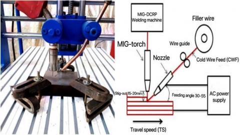
Figure 1 depicts the integrated components of the computer-aided double-wire deposition machine (CADWDM) system.
The development and construction of the 3-axis machine was undertaken with the objective of facilitating the SMD process. A preliminary design for the proposed Computer-Aided Design and Water Dispensing (CADWD) machine was initially developed.
Figure 1. (a) a basic overview of the SMD system and (b) a close-up of the deposition tool
The CADWDM system comprises several components, including a machine body, a deposition tool (DT), a gantry that provides support for the DT (consisting of a welding torch and cold wire), and facilitates their movement in three axes using motors. Additionally, the system includes a worktable and adjustable fixtures that are designed to accommodate torches and cold feed wire. The DT connector serves the purpose of linking the MIG-welding torch to the cold wire feed device, while also facilitating the control of the external wire feed mechanism. The MIG Lincoln welding equipment is equipped with an arc heat source that produces a significant amount of heat, resulting in the melting of materials. This heat source is capable of generating a direct current (DC) MIG arc, which operates in reverse polarity. The material used as the base for applying the weld beads was a low carbon steel of St 3 grade [31], which had dimensions of 150mm × 100mm × 8mm. The filler material used for the deposit was a 1.2 mm diameter stainless steel wire known as Flux-Core-Shield-Bright 309L. As shown by the study [32], the utilization of this particular type of filler wire obviates the need for gas shielding during the deposition process, hence providing automatic protection for the metal surface.
In this work, a range of arc currents and travel rates (3 - 5 mm/min) were employed to deposit beads with different wire ratio speeds. The wire ratio speeds started at 1.5 m/min and were incrementally increased by 0.5 m/min until the deposition process reached an excess of wire amounting to 2.5 m/min. Subsequently, the technique was replicated for the remaining sets of arc current and traverse speed. Table 1 presents the quantitative analysis (in w%) of the substrate and filler metal's chemical makeup. The beads located on the plate were arranged in a parallel manner with respect to the welding direction, namely aligned along the x-axis. The inter-centerline spacing of the beads remained constant at a measurement of 15 mm. Table 2 displays the consistent circumstances of the process parameters. The primary MIG torch exhibits a 90-degree angle, whereas the angle between the nozzle cold wire feed (CWF) containing 4043 aluminum alloy filler material and the workpiece material is 30 degrees, as indicated in Table 2.
Table 1. Laboratory examination of the filler material, cold wire feed, and substrates chemical composition
|
Materials |
Wire |
4043 Al |
Substrate |
|
C |
0.03% |
--- |
0.1 Max |
|
%Si |
0.90% |
5.04 |
0.03-0.15 |
|
Mn |
1.30% |
0.0011 |
0.2-0.45 |
|
S |
--- |
--- |
0.04 |
|
P |
--- |
---- |
0.04 |
|
Mo |
0.10% |
--- |
--- |
|
Ni |
12.50% |
--- |
--- |
|
Cr |
24% |
--- |
--- |
|
Cu |
0.10% |
0.03 |
--- |
|
Fe |
rem. |
0.134 |
rem. |
|
Mg |
---- |
0.0017 |
---- |
|
Zn |
---- |
0.001 |
---- |
|
Al |
---- |
94.7 |
---- |
Table 2. The constant parameters utilized during the deposition process
|
Parameter |
Unit |
Value |
|
Current |
A |
160 |
|
Polarity |
--- |
DCRP |
|
Arc length |
mm |
1 |
|
Torch angle |
Degree |
90 |
|
Feeding angle |
Degree |
30 |
|
Wire stick-out |
mm |
15 [18, 19] |
2.2 Microstructure and mechanical tests
In order to comprehend the variability in microstructure structure, it is important to do a thorough analysis of the stages involved in the production of microstructure grain within contemporary SMD (Surface Mount Device) techniques. Microphotographs were acquired through the utilization of optical microscopy and scanning electron microscopy (SEM) analysis. Following the completion of the final round of polishing, the samples underwent a cleaning process including tap water, followed by ethanol, and ultimately dried using hot air. The specimens underwent electro-etching for a duration of 50 seconds, employing a voltage of 9 volts. The etching solution consisted of 10 grammes of oxalic acid dissolved in 100 milliliters of distilled water. The Vickers hardness apparatus was employed to do hardness testing. The specimens for the tensile test were subjected to testing using a Universal Tensile machine, which had a maximum capacity of 200 kilonewtons. The specimens have been prepared from various locations and orientations in accordance with the ISO/ASTM 52900/2015 standard [33].
3.1 Microstructure of additively manufactured SS309L (without and with the addition of aluminium)
There are several challenges associated with AM of metals and alloys, one of which is that the microstructure of additively manufactured parts can be different from conventionally produced parts, and this can affect their properties.
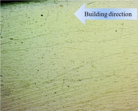
When WAAM prepared SS 309L, the microstructure typically consists of elongated grains in the building direction, as shown in Figure 2. This means that the grains in the metal part are oriented along the direction in which the part was built, rather than being randomly oriented as in conventionally produced parts. These elongated grains are formed due to the solidification process that takes place during the steps of AM. At the begging of these steps, a layer of material is deposited on a metallic build substrate. This process is repeated until the whole part is built. The deposition of each layer produces a temperature gradient in the part, with the hottest top surface (in the liquid state or just solidified) and the coolest bottom surface. This temperature gradient results in the growing of the grains in the part in the direction of heat flow, which is perpendicular to the building substrate.
In general, the microstructure of WAAM-produced SS 309L is influenced by the cooling rate during solidification, which affects the formation of various microstructural features such as dendrites and grain boundaries. Without the addition of aluminium, the microstructure is not significantly altered, although the material exhibits some degree of porosity due to the nature of the WAAM process.
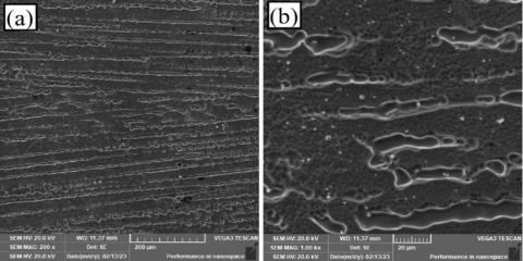
More details in the microstructure could be seen when using SEM for the same sample of SS 309L (see Figure 3). The microstructure of WAAM-produced SS 309L shows some dendritic structure. These dendrites are formed during solidification and can be observed as elongated structures extending along the building direction.
At higher magnifications, the microstructure of WAAM-produced SS 309L shows more details of the dendritic structure and the grain boundaries. The dendrites comprise a primary phase rich in chromium and nickel and a secondary phase enriched in manganese, silicon, and carbon. The secondary phase is typically present as small precipitates within the dendrites and at the grain boundaries [34], as shown in Figure 3b.
Figure 2. OM image for the microstructure of the SS 309L prepared by WAAM without adding aluminium (without any heat treatment)
According to Astafurov and Astafurova [35], the solidification of some stainless steels (for example AISI 304, 304L, and 308L) produced by different AM processes (such as EBAM-fabricated specimens), starts by the formation of austenitic dendrites from the melt at the early stages (primarily austenitic structure) followed by the formation of ferrite in the interdendritic areas between austenite. Different morphology could be detected for the ferrite colonies including point-like, cellular, vermiculate, or lathy. A microstructure with two phases (γ+δ) is predictable in AISI 304/308 sheets of steel produced using AM taking into consideration the Creq/Nieq ratio. Nevertheless, AM process parameters (such as heat input value) could affect the morphology of the phases and their ratio [35].
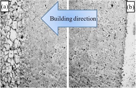
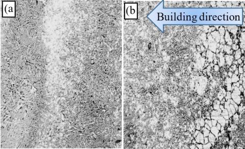
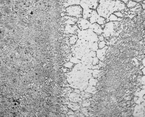
A dramatic change in the microstructure could be seen when SS 309L is prepared by Wire Arc Additive Manufacturing (WAAM) with the addition of 2.5 wt. % Al. The resulting microstructure shows a mixture of austenitic and ferritic phases [36]. The addition of aluminium can promote ferrite formation in the microstructure, as shown in Figure 4. This figure shows two main distinct main regions. The first one (light region) consists of large grains which are generally austenite surrounded by some particles around the grain boundary (see Figure 5), this region represents the layer where no aluminium was added. On the other hand, the second region (the darker region) consists of very fine grains with two phases (austenite and ferrite).
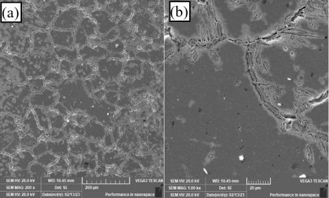
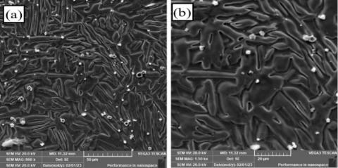
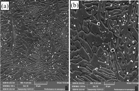
More detailed microstructure images can be seen in Figure 5. The SEM image shows an overview of the microstructure of the first region (light region), revealing the presence of large grains (austenite) surrounded by intermittent lamella of another phase. The second phase is supposed to be ferrite. The presence of ferrite at this region may be attributed to the diffusion of some aluminium during the AM process from the region with aluminium addition to the region without addition. However, the amount of diffused aluminium could not alter all the microstructure in this region. The addition of 2.5 wt. % Al promotes the formation of ferrite, leading to a more heterogeneous microstructure compared to SS 309L without any Al addition. The nature and distribution of these phases will depend on the specific composition of the material and the processing conditions used during WAAM as shown in Figure 5.
Overall, SEM imaging can provide valuable information about the microstructure of SS 309L prepared by WAAM with the addition of 2.5 wt. % Al without any heat treatment, which can help to understand its mechanical properties and performance.
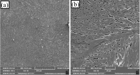
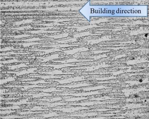
The addition of 5 wt. % Al (adding aluminium to all layers) can significantly affect the microstructure of SS 309L, promoting the formation of ferrite. The resulting microstructure is more heterogeneous and complex than that of SS 309L without any Al addition as shown in Figure 6.
In OM images, the microstructure shows more refining effect when adding 5% Al compared to the same material with 2.5% Al addition (see Figure 4).
The refining effect resulted from the addition of aluminium, which shifted the structure of the SS alloy from a single austenitic phase to a duplex Austenitic-Ferritic alloy, which can be seen by comparing the SEM images with the same magnification in Figure 5 and Figure 7. However, some large austenite grains still appear in some regions in the form of separated islands. This means that the content of aluminium in these regions is low.
Figure 3. SEM with different magnifications for the microstructure of the SS 309L prepared by WAAM (without any heat treatment)
Figure 4. OM image for the microstructure of the SS 309L prepared by WAAM with the addition of 2.5 wt. % Al as a percent of the overall weight of SS 309L (Without any heat treatment)
Figure 5. SEM with different magnifications for the microstructure of the SS 309L prepared by WAAM with the addition of 2.5 wt. % Al as a percent of the overall weight of SS 309L (Without any heat treatment)
Figure 6. OM image for the microstructure of the SS 309L prepared by WAAM with the addition of 5 wt. % Al as a per cent of the overall weight of SS 309L. (Without any heat treatment)
Figure 7. SEM with different magnifications for the microstructure of the SS 309L prepared by WAAM with the addition of 5 wt. % Al as a per cent of the overall weight of SS 309L (Without any heat treatment)
After heat treatment of SS 309L prepared by WAAM specimens at 1150℃ for 4 hours followed by water quenching, they showed clear changes. Figure 8 shows an optical microscope image of SS 309L prepared by WAAM, the microstructure appears homogenous with fine grain size and consists of two distinct regions. A clear phase with a nearly net shape elongated in the building direction can be seen. These dark regions in the structure may be attributed to the presence of the ferrite phase. Whereas, a brighter region (matrix) is mostly expected to be of austenite. Grain boundaries also are visible, appearing as thin lines separating the different grains. These structures could not be seen in the OM image of the specimens before heat treatment (see Figure 2). However, this structure seems to be slightly similar to that seen in SEM images in Figure 3 with clear links between the grains of the second phase (dark phase) in Figure 8. The microstructure present in such alloy depends on the specific heat treatment conditions used and other factors such as the cooling rate during heat treatment, the initial grain size and distribution, and any residual stresses in the material.
Most of the grains stile have directional structure (depending on the process procedure or in other words the building direction) even after the heat treatment of the specimens. This conclusion allows for a better understanding of the material properties and potential applications of this process.
The OM image of the microstructure of SS 309L with 2.5 wt. % Al after heat treatment shows a typical duplex structure consisting of austenitic and ferritic phases. Adding Al can promote the formation of second phases which can influence the microstructure and properties of the alloy as shown in Figure 9.
The effect of heat treatment can be seen on the microstructure when comparing Figure 9 with Figure 4. The size of the single bright region (the austenite) was reduced dramatically offset by an increase in the two phases region. This change in the microstructure may be attributed to the diffusion of aluminium from the high aluminium concentration layers (two-phase layers) to the layers without aluminium (single-phase layer). The interesting thing about the figure is that the penetration of the second phase to the single-phase region extended in the grain boundaries which are the preferred path for the diffusion of aluminium atoms.
The overall morphology of the microstructure, with the austenitic and ferritic phases appearing as distinct regions with different shades or colours. The grain size and shape of the double-phase region remain without visible changes compared to that of the same alloy before heat treatment. The SEM image (Figure 10) shows the overall morphology of the microstructure, with the austenitic and ferritic phases. In this region, a fine-grain structure can be seen.
The higher magnification for the sample in Figure 8 using SEM revealed different microstructures. The morphology of the grains of the secondary phase present in Figure 11, seems to be uncourteous islands instead of a net-shaped structure. The grains appear as distinct regions of different brightness or contrast elongated in the building direction.
Figure 8. OM image for the microstructure of the SS 309L prepared by WAAM without the addition of aluminium (Heat treated)
Figure 9. OM image for the microstructure of the SS 309L prepared by WAAM with the addition of 2.5 wt. % Al as a per cent of the overall weight of SS 309L (Heat treated)
Figure 10. SEM with different magnifications for the microstructure of the SS 309L prepared by WAAM with the addition of 2.5 wt. % Al as a per cent of the overall weight of SS 309L (Heat treated)
Figure 11. SEM with different magnifications for the microstructure of the SS 309L prepared by WAAM
These grains have complex branched shapes completely different to that seen in the equiaxed austenite grains of the original material (without the addition of aluminium).
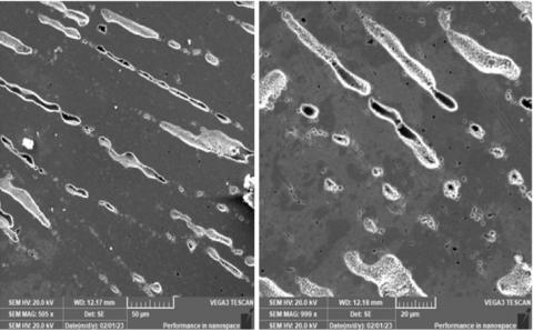
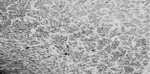
With further increase in the addition of aluminium to 5 wt. % Al and heat treatment, the microstructure of SS 309L became significantly different from the alloy without any aluminium addition. After heat treatment, the microstructure tends to show a more homogeneous distribution of these phases throughout the material. The microstructure is to consist of a fine-grained matrix with a uniformly dispersed second phase resulting in a structure similar to the eutectic structure as shown in Figure 12. However, the general view of the distribution of the different phases provided by the SEM image (Figure 13) shows details for the microstructure similar to that seen in Figure 10 with grains having different sizes and morphologies.
Figure 12. OM image for the microstructure of the SS 309L prepared by WAAM with the addition of 5 wt. % Al as a per cent of the overall weight of SS 309L (Heat treated)
Figure 13. SEM with different magnifications for the microstructure of the SS 309L prepared by WAAM with the addition of 5 wt. % Al as a per cent of the overall weight of SS 309L (Heat treated)
3.2 Effect of cold feeding on hardness
The microhardness measurements were made along the centerline of the vertical section for all the deposited walls to demonstrate the variations in the hardness values across the entire sample. The average of at least three measurements obtained in the same area was the basis for all hardness values.
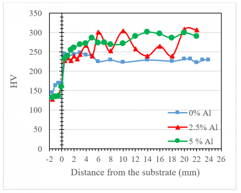
In the as-deposited wall (Figure 14) without Cold wire feed (CWF-4043Al), the microhardness measurement finds location-dependent reading variations. At the zero line (the interface between the substrate and the built-up walls), the hardness increased rapidly due to the transfer from the material of the substrate (carbon steel) to the wall’s material (stainless steel). The hardness on both sides of the interface shows a clear change in its level. It is increased in the side of the carbon steel and decreased in the side of stainless steel due to the inter-diffusion of carbon and other alloying elements which changes the chemical composition in these regions and as a result the structure and local properties. However, because the change in hardness level extended only one millimetre or less through the wall material, therefore, this region is not very important in terms of the overall microstructure and mechanical properties of the walls especially when considering that this region will be removed during the finishing of any component. After the base region, the hardness continued at almost the same level and shows very slight fluctuations. This stability in hardness level may be attributed to the little variation in the microstructures.
Figure 14. Microhardness distribution along the vertical section of the deposited walls before Heat-Treatment
Adding cold wire feeding (CWF-4043Al) to the base material greatly influenced the hardness values. However, the hardness homogeneity was significantly affected by the addition of Al (layer by layer). The hardness shows a very high level in the layers with Al addition and lower hardness in the layers without additions. This fluctuation can be seen in the samples with overall additions of 2.5% Al. The main reason behind the increase in hardness is the shifting of the microstructure of the regions with aluminium additions to a microstructure consisting of two very fine phases. On the other hand, the specimens with full aluminium additions of 5% Al (in all layers) show much less fluctuation in hardness level due to the change of the microstructure of the alloy to almost completely two fine grains phases in all regions.
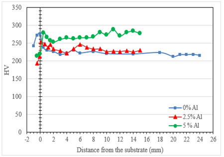
The fluctuation in the hardness level could be reduced by applying heat treatment to all samples. This heat treatment almost homogenized the microstructure and resulted in more homogeneous properties compared to the structure before the treatment. Figure 15 shows the hardness profile of the longitudinal section of the three walls (with the addition of 0, 2.5 and 5% Al). From the same figure, it can be noticed that the curve levels and profile have changed dramatically as compared to Figure 14. Though, the clearest change could be seen in the behaviour of the wall with the 2.5% Al addition. Most of the fluctuations seen in the hardness level in Figure 15 almost disappeared after heat treatment. This change is a result of the change in the microstructure of this alloy after heat treatment. Where the microstructure became more homogeneous consists.
Another interesting change that can be noticed after heat treatment is the hardness level at and near the interface between the substrate (carbon steel) and the built walls. For example, in the sample of SS without the addition of aluminium, the hardness increased at this region from almost 170 HV to about 270 HV. This change can be attributed to the interdiffusion of carbon, chromium and other alloying elements at the high temperature of the heat treatment which promoted the production of carbides and other hardening compounds. However, this region extends almost one millimeter through the wall material and does not affect the properties (the hardness) far away from the interface.
Figure 15. Microhardness distribution along the vertical section of the deposited walls after Heat-Treatment
3.3 Effect of cold feeding on tensile test
Stress-strain curve of the material shows the relationship between the applied stress and the resulting strain under tensile loading conditions.
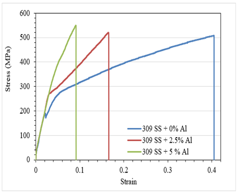
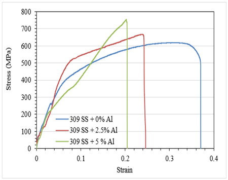
In general, the tensile curve for additively manufactured SS 309L exhibits several distinct regions: elastic deformation, yielding, plastic deformation, and fracture as shown in Figure 16. for the horizontal samples of SS309L with and without (CWF-4043Al) addition. At the beginning of the tensile test, when a load is applied, the specimen undergoes elastic deformation. In this region, the material elongates proportionally to the applied stress. As the applied stress increases, the material reaches its yield point. At this point, the stainless steel begins to exhibit plastic deformation, and the stress-strain curve deviates from linearity. After the yield point, the stainless steel continues to deform plastically without further increase in stress. The material undergoes significant strain in this region, also known as the plastic or strain-hardening region.
The strain-hardening behaviour contributes to an increase in material strength and ductility. The stress-strain curve reaches its ultimate tensile strength (UTS) at the point of maximum stress. Beyond the UTS, the material experiences necking, where localized deformation and reduction in the cross-sectional area occur. Eventually, the material reaches its breaking point, leading to fracture.
The addition of (CWF-4043Al) to stainless steel 309L could modify the tensile behaviour of the material. However, the specific effects on the tensile curve depend on various factors such as the percentage of (CWF-4043Al) added and the resulting microstructure of the material. In general, the addition of (CWF-4043Al) enhanced the strength of stainless steel due to the change in the microstructure of the resulting alloy. The change of the microstructure of the alloy from austenitic (with some ferrite) to duplex due to the addition of (CWF-4043Al) which also refined the grain structure led to improving the tensile strength and reducing the ductility.
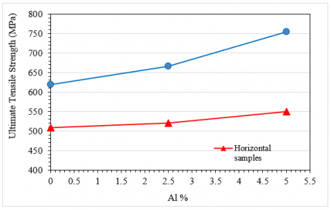
The stress-strain behaviors of vertical specimens of SS309L with and without (CWF-4043Al) addition (Figure 17) are also different due to the changes in the microstructure of the alloy. Overall, adding Al to SS309L increased the yield strength and ultimate tensile strength but also decrease its ductility. Therefore, the stress-strain curve of a vertical sample of SS309L with Al addition shows a higher yield point and more significant strain hardening than a vertical sample of SS309L without Al addition and this effect increases with increasing the Al additions from 2.5% to 5%. Generally, by comparing Figure 15 and Figure 16, the ultimate tensile strength shows much higher levels in the vertical specimens compared to the horizontal specimens.
This can be attributed to the directional nature of the microstructure of the built material. The combined effect of (CWF-4043Al) addition with the direction of specimens on the ultimate tensile strength of the alloys is shown in Figure 18. The tensile strength in both directions increased with increasing the aluminium additions. However, a clear difference can be seen between the two curves of the horizontal and vertical specimens due to the reasons mentioned above.
Figure 16. Stress-strain curves of horizontal samples with and without the addition of aluminium
Figure 17. Stress-strain curves of vertical samples with and without the addition of aluminium
Figure 18. Tensile strength as a function of the addition of aluminium
This study investigated the effects of adding aluminium as an additional alloying element to austenitic stainless-steel SS 309L using Additive Manufacturing (AM) technology. The microstructure and mechanical properties of the additively manufactured SS309L with varying percentages of external aluminium alloy 4043 were analyzed using optical microscopy (OM) and scanning electron microscopy (SEM). Extensive testing was conducted to assess the mechanical properties of the additively manufactured SS309L with and without aluminium addition. The results of this study demonstrate that the addition of aluminium significantly affects the mechanical properties of the deposited portions. The microstructure of the additively manufactured SS309L with aluminium addition showed a more refined and uniform structure, resulting in improved mechanical properties such as hardness and tensile strength. The study also found that heat treatment can further enhance the mechanical properties of the additively manufactured SS309L. The implications of these findings are significant for the field of additive manufacturing, as they provide insights into how the addition of aluminium can be used to optimize the microstructure and mechanical properties of SS 309L. These findings could potentially open new avenues for the optimization of additive manufacturing processes, leading to the development of stronger and more durable components. Future research could focus on further exploring the effects of different alloying elements on the microstructure and mechanical properties of additively manufactured stainless steels. Additionally, research could investigate the impact of different manufacturing techniques and process parameters on the properties of additively manufactured components. In summary, this study advances our understanding of how aluminium addition influences the microstructure and mechanical properties of SS 309L, providing valuable insights into the optimization of additive manufacturing processes.
This research was carried out at the University of Babylon in Babylon, Iraq. In addition, the University of Thi-Qar/Faculty of Engineering, Iraq, Thi-Qar collaborated.
Rania Ali: investigated the analytical methods. Basem Al-Zubaidy: verified the analytical methods and discussed the results.
[1] Brandl, E., Heckenberger, U., Holzinger, V., Buchbinder, D. (2012). Additive manufactured AlSi10Mg samples using Selective Laser Melting (SLM): Microstructure, high cycle fatigue, and fracture behavior. Materials & Design, 34: 159-169. https://doi.org/10.1016/j.matdes.2011.07.067
[2] Chen, J., Hou, W., Wang, X.Z., Chu, S.L., Yang, Z.Y. (2020). Microstructure, porosity and mechanical properties of selective laser melted AlSi10Mg. Chinese Journal of Aeronautics, 33(7): 2043-2054. https://doi.org/10.1016/j.cja.2019.08.017
[3] Gupta, M.K., Singla, A.K., Ji, H., Song, Q., Liu, Z., Cai, W., Mia, M., Khanna, N., Krolczyk, G.M. (2020). Impact of layer rotation on micro-structure, grain size, surface integrity and mechanical behaviour of SLM Al-Si-10Mg alloy. Journal of Materials Research and Technology, 9(5): 9506-9522. https://doi.org/10.1016/j.jmrt.2020.06.090
[4] Del Guercio, G., Galati, M., Saboori, A., Fino, P., Iuliano, L. (2020). Microstructure and mechanical performance of Ti–6Al–4V lattice structures manufactured via electron beam melting (EBM): A review. Acta Metallurgica Sinica (English Letters), 33: 183-203. https://doi.org/10.1007/s40195-020-00998-1
[5] Li, Z., Chen, J., Sui, S., Zhong, C., Lu, X., Lin, X. (2020). The microstructure evolution and tensile properties of Inconel 718 fabricated by high-deposition-rate laser directed energy deposition. Additive Manufacturing, 31: 100941. https://doi.org/10.1016/j.addma.2019.100941
[6] Konda Gokuldoss, P., Kolla, S., Eckert, J. (2017). Additive manufacturing processes: Selective laser melting, electron beam melting and binder jetting—Selection guidelines. Materials, 10(6): 672. https://doi.org/10.3390/ma10060672
[7] Zhong, Y., Rännar, L.E., Liu, L., Koptyug, A., Wikman, S., Olsen, J., Cai, D.Q., Shen, Z. (2017). Additive manufacturing of 316L stainless steel by electron beam melting for nuclear fusion applications. Journal of Nuclear Materials, 486: 234-245. https://doi.org/10.1016/j.jnucmat.2016.12.042
[8] Ugla, A.A., Yilmaz, O., Almusawi, A.R. (2018). Development and control of shaped metal deposition process using tungsten inert gas arc heat source in additive layered manufacturing. Proceedings of the Institution of Mechanical Engineers, Part B: Journal of Engineering Manufacture, 232(9): 1628-1641. https://doi.org/10.1177/0954405416673112
[9] Ugla, A., Kamil, D.J., J Khaudair, H. (2020). Quality improvement of shaped metal deposited components using non-traditional techniques: A review. International Journal of Mechanical and Production Engineering Research and Development (IJMPERD), 10(3): 2411-2430.
[10] Ugla, A., J Khaudair, H., Almusawi, A.R. (2019). Metal inert gas welding-based-shaped metal deposition in additive layered manufacturing: A review. World Academy of Science, Engineering and Technology International Journal of Mechanical and Materials Engineering, 13(3): 244-257.
[11] Ugla, A., J Khaudair, H. (2018). Optimization of double-wire mig based shaped metal deposition process parameters OF3-D printed AISI 309L parts. International Journal of Mechanical Engineering and Technology, 9(11): 2438-2452.
[12] Ugla, A.A., Kamil, D.J., Ibrahim, Z.A., Khudair, H.J. (2020) Improvement characteristics of the shaped metal deposited component using external excited system. Journal of Critical Reviews, 7(5): 2394-5125.
[13] Khaudair, H.J., Ugla, A.A., Almusawi, A.R. (2021). Design, integrating and controlling of mig-based shaped metal deposition system with externally cold wire feed in additive layered manufacturing technology. Arabian Journal for Science and Engineering, 46(3): 2677-2690. https://doi.org/10.1007/s13369-020-05100-6
[14] Mugada, K.K., Sivanandam, A., Digavalli, R.K. (2020). Wire+ Arc additive manufacturing of metals: State of the art and challenges. In Additive Manufacturing Applications for Metals and Composites, pp. 106-126. https://doi.org/10.4018/978-1-7998-4054-1.ch006
[15] Clark, D., Bache, M.R., Whittaker, M.T. (2008). Shaped metal deposition of a nickel alloy for aero engine applications. Journal of Materials Processing Technology, 203(1-3): 439-448. https://doi.org/10.1016/j.jmatprotec.2007.10.051
[16] Skiba, T., Baufeld, B., Van der Biest, O. (2011). Shaped metal deposition of 300M steel. Proceedings of the Institution of Mechanical Engineers, Part B: Journal of Engineering Manufacture, 225(6): 831-839. https://doi.org/10.1177/09544054jem2115
[17] Skiba, T., Baufeld, B., Van der Biest, O. (2009). Microstructure and mechanical properties of stainless steel component manufactured by shaped metal deposition. ISIJ International, 49(10): 1588-1591. https://doi.org/10.2355/isijinternational.49.1588
[18] Ugla, A.A., Yilmaz, O. (2017). Deposition-path generation of SS308 components manufactured by TIG welding-based shaped metal deposition process. Arabian Journal for Science and Engineering, 42: 4701-4711. https://doi.org/10.1007/s13369-017-2582-3
[19] Katou, M., Oh, J., Miyamoto, Y., Matsuura, K., Kudoh, M. (2007). Freeform fabrication of titanium metal and intermetallic alloys by three-dimensional micro welding. Materials & Design, 28(7): 2093-2098. https://doi.org/10.1016/j.matdes.2006.05.024
[20] Charles, C., Järvstråt, N. (2007). Development of a microstructure model for metal deposition of titanium alloy Ti-6Al-4V. In 11th World Conference on Titanium (JIMIC 5), Kyoto, Japan, pp. 1201-1205.
[21] Tancogne-Dejean, T., Roth, C.C., Woy, U., Mohr, D. (2016). Probabilistic fracture of Ti–6Al–4V made through additive layer manufacturing. International Journal of Plasticity, 78: 145-172. https://doi.org/10.1016/j.ijplas.2015.09.007
[22] Neikter, M., Åkerfeldt, P., Pederson, R., Antti, M.L., Sandell, V. (2018). Microstructural characterization and comparison of Ti-6Al-4V manufactured with different additive manufacturing processes. Materials Characterization, 143: 68-75. https://doi.org/10.1016/j.matchar.2018.02.003
[23] Baufeld, B., Biest, O.V.D., Gault, R. (2009). Microstructure of Ti-6Al-4V specimens produced by shaped metal deposition. International Journal of Materials Research, 100(11): 1536-1542. https://doi.org/10.3139/146.110217
[24] Baufeld, B., Van Der Biest, O., Gault, R., Ridgway, K. (2011). Manufacturing Ti-6Al-4V components by shaped metal deposition: microstructure and mechanical properties. In IOP Conference Series: Materials Science And Engineering, Sheffield, UK, 26(1): 012001. https://doi.org/10.1088/1757-899x/26/1/012001
[25] Baufeld, B. (2012). Mechanical properties of INCONEL 718 parts manufactured by shaped metal deposition (SMD). Journal of Materials Engineering and Performance, 21: 1416-1421. https://doi.org/10.1007/s11665-011-0009-y
[26] Washko, S. D., and Aggen, G., (1990). Wrought stainless steels. In Properties and Selection: Irons, Steels, and High-Performance Alloys, ASM Handbook Committee. pp. 841-907. https://doi.org/10.31399/asm.hb.v01.a0001046
[27] Parr, J.G. (1971). An Introduction to Stainless Steel, 2nd Printing. American Society for Metals, Metals Park.
[28] ESAB, A. (2023). ESAB Corporation is a world leader in fabrication and specialty gas control technology, providing our partners with advanced equipment, consumables, automation, robotics, and digital solutions which enable the everyday and extraordinary work that shapes our world. [cited 2023; 1st:[Available from: http://www.esabna.com/shared/documents/litdownloads/weldingfmdb/files/assets/basic-html/page428.html.
[29] Yilmaz, O., Ugla, A.A. (2017). Microstructure characterization of SS308LSi components manufactured by GTAW-based additive manufacturing: Shaped metal deposition using pulsed current arc. The International Journal of Advanced Manufacturing Technology, 89: 13-25. https://doi.org/10.1007/s00170-016-9053-y
[30] Khaudair, H.J., Ugla, A.A., Almusawi, A.R. (2021). Effect of double wire cold feed on characteristics of additive manufactured components. Journal of Materials Engineering and Performance, 30(9): 6801-6807. https://doi.org/10.1007/s11665-021-06006-6
[31] D.I.N. (1976). Steel and Iron Standards on Quality. 24th revised edition, Deutsches Institute Fur Normunge, Berlin.
[32] Messler Jr, R.W. (2008). Principles of Welding: Processes, Physics, Chemistry, and Metallurgy. John Wiley & Sons, Singapore.
[33] ISO (2015). ISO/ASTM 52900: 2015 additive manufacturing–general principles–terminology. ASTM F2792-10e1, 1-19.
[34] He, S., Shang, H., Fernández-Caballero, A., Warren, A.D., Knowles, D.M., Flewitt, P.E.J., Martin, T.L. (2021). The role of grain boundary ferrite evolution and thermal aging on creep cavitation of type 316H austenitic stainless steel. Materials Science and Engineering: A, 807: 140859. https://doi.org/10.1016/j.msea.2021.140859
[35] Astafurov, S., Astafurova, E. (2021). Phase composition of austenitic stainless steels in additive manufacturing: A review. Metals, 11(7): 1052. https://doi.org/10.3390/met11071052
[36] Zhang, Y., Cheng, F., Wu, S. (2021). The microstructure and mechanical properties of duplex stainless steel components fabricated via flux-cored wire arc-additive manufacturing. Journal of Manufacturing Processes, 69: 204-214. https://doi.org/10.1016/j.jmapro.2021.07.045