Ramgopal Reddy Bijjam* | Srinivas Chandanam | Govind Nandipati | Sneha H. Dhoria
© 2022 IIETA. This article is published by IIETA and is licensed under the CC BY 4.0 license (http://creativecommons.org/licenses/by/4.0/).
OPEN ACCESS
Significance of composite materials is increasing enormously in the progress of modern science and technology. The composites can be transformed into suitable components with high precision by machining, which can be used for present day applications. Drilling is crucial operation that is often used in the assembly of composite parts to obtain finished product. But the drilling induced damage may affect the performance of the composite. The present work is focused on the impact of various parameters in drilling like feed rate, spindle speed and drill diameter on surface roughness and delamination of glass/hemp/bamboo fibers embedded polymer hybrid composites. The composite is prepared by hand layup method. The drilling on composite is done on a CNC drilling machine and the maximum diameter due to delamination is measured using profile projector. To optimize drilling parameters for the sake of reducing the surface roughness and delamination factor, Taguchi method applied. The measured results are analyzed using commercially available software package Minitab19. The analysis is carried out using ANOVA (Analysis of Variance). In order to obtain best optimal conditions GRA (Grey Relational Analysis) is adopted. The results show that among all important parameters, feed rate and drill diameter are more crucial for surface roughness, whereas delamination is impacted by feed rate and speed of spindle.
glass/hemp/bamboo fibers reinforced polymer hybrid composites, drilling parameters, Taguchi method: ANOVA, surface roughness, delamination factor, grey relational analysis
A composite is one which is having two or more components is to take benefit of the excellent properties of either the components without sacrificing on the fragility of the components. It offers many benefits over conventional materials. Composites are designed with a particular use in mind such as light weight, high strength, design flexibility, dimensional stability, resistance to corrosion and less tooling costs. Among all composites, glass fibre embedded composites enjoy popularity in structural components due to their good strength-to-weight ratio, outstanding fracture toughness and excellent design flexibility.
Manufacturing of composite materials requires variety of operations that would vary depending upon existing technology, available facilities and personnel skill. The manufacturing process would vary depending on composite materials and their application. The fabrication of fibre embedded polymer composites can generally be divided into primary and secondary methods. Hand lay-up method is one among the oldest primary fabrication method that is popularly used in the manufacturing of composites. The assembly of composite parts requires machining operation. Drilling is a crucial cutting operation that is commonly used in the assembly of the parts.
Number of techniques are used for performing holes in composites. These methods result in delamination damage, poor surface finish, cracks in micro level, pull out of fibre, burning of matrix surrounding the hole. Drilling of holes of poor quality such as delamination damage, poor surface finish etc., result out of tolerance limits of assembly and which may impact the structural properties of assembly in long term. Hence, it is very crucial to know the impact of drilling parameters on surface finish and delamination.
Several researchers were investigated the impact of input factors of composites. The various related works are classified into four categories depending on materials, input factors, output responses and methodology used to optimize the machining parameters. Kilickap [1] investigated the effect of input characteristics in drilling on surface roughness and delamination of GFRP (glass fibre reinforced polymer composites). Results show that the point angle impacts the surface roughness and cutting speed and feed rate impacts the delamination. Murthy et al. [2] presented the influence of machining factors in the drilling of glass fibre embedded polymer composites laminate. The results reveal that delamination damage impacted by diameter of drill, feed rate, speed of spindle, material thickness and point angle. The results also show that increase in the level of independent parameters increase delamination except for the spindle speed. Othman et al. [3] studied the drilling input variables in CFRP (carbon fibre embedded polymers) using three types of drills such as dagger, brad and twist drills. The results show that the thrust force is greatly impacted by feed rate, which reflects the wear of tool and quality of hole. Hocheng and Tsao [4] presented a detailed study on delamination of drilling composites by using different drill types.
Babu and Sunny [5] conducted the experiments using Taguchi experimental design by using three different types of tools, studied the influence of feed rate and drilling speed on the delamination damage of GFRP composite materials. Ramesh et al. [6] investigated the mechanical characteristics of glass and flax fibres embedded polymer composites. Singh and Bhatnagar [7] made a good effort to relate the machining parameters and damage induced by drilling. The results reveal that cutting speed to feed ratio effects the damage induced by drilling.
Babu et al. [8] used Taguchi DOE and Analysis of Variance to investigate the impact of drilling characteristics and combination of parameters on the delamination damage and tensile strength of unidirectional hemp fibre embedded composites. The results reported that spindle speed and feed rate are the more significant characteristics on delamination damage and tensile strength. Ramesh and Gopinath [9] investigated the impact of machining characteristics on thrust force in drilling of glass/sisal fibre embedded polymer composite plates by adopting Response Surface Methodology (RSM). The results reveal that thrust force is greatly impacted by the parameter speed of spindle and least influencing parameter is drill diameter. Kaybal et al. [10] studied the machinability, the effects of feed rate and cutting speed on delamination damage and thrust force in caron nanotube (CNT) embedded CFRP. The results indicated that combined effect of low feed with machining speed is required to decrease delamination damage in machining of Carbon Fibre embedded Polymers.
Review of literature demonstrated that lot of work was done on optimization of drilling parameters of GFRP and CFRP based composites for optimizing the delamination factor, surface roughness and thrust force by using Taguchi design of experiments, ANOVA and response surface methodology. But very limited research work done on GFRP based hybrid composites and using Grey Relational Analysis (GRA). In this paper experiments are carried out using Taguchi’s L9 orthogonal array on Glass/Hemp/Bamboo fibres based composites prepared by hand lay-up technique. The input factors selected are drill diameter, spindle speed and feed rate. To investigate the influence of drilling parameters on quality targets of delamination damage and surface roughness a GRA is used.
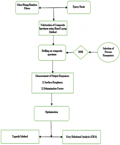
In this study, Glass/hemp/bamboo fibres reinforced polymer hybrid composite plate of size 300 x 150 x 20 mm is prepared by using hand lay-up technique. The fibres used in the composite are 450 GSM chopped glass fibre mat, 200 GSM woven Glass fibre mat, Hemp fibre mat, Bamboo fibres are incorporated in the order of chopped fibre mat/woven fibre mat/hemp fibre mat/woven fibre mat/bamboo fibre/woven fibre mat/hemp fibre mat/woven fibre mat/chopped fibre mat, Epoxy LY556 as matrix and hardener HY 951. In order to get the required thickness of 20 mm, number of layers were stacked in the above sequence and the fibre volume fraction of 0.65. Figure 1 shows the methodology and optimization of glass/hemp/bamboo fibres reinforced polymer hybrid composite. The materials used to fabricate the hybrid composite by hand layup method is 50% Glass fiber, 10% Hemp fibre, 5% Bamboo fibre and remaining is epoxy resin (35%). Taguchi L9 standard array is used for design of experiments in drilling of hybrid composite material. This basic design uses three input parameters, each with three levels. The impact of drilling factors on surface roughness and delamination damage is determined by employing Grey relational analysis.
Figure 1. Methodology and optimization of current research problem
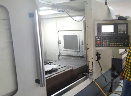
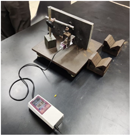
The drilling on the composite is done on Computer Numerical Control machine shown in Figure 2. The drilling of holes is performed according to the certain input parameters like feed rate, speed of spindle and drill diameter. Taking these input parameters with three levels and Taguchi methodology of orthogonal arrays, L9 orthogonal array is used.
Figure 2. CNC drilling machine
Figure 3. Drill bits of 8, 10 and 12 mm diameters
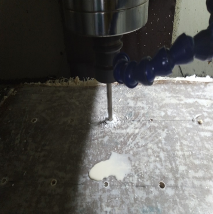
Figure 4. Drilling on hybrid composite material
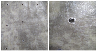
Figure 5. Delamination in a drilled hole
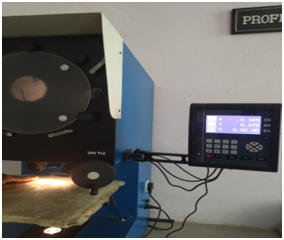
Figure 6. Measuring of delaminated zone using profile projector
Figure 7. Measuring of surface roughness using Mitutoyo surface roughness tester
The drill bits of three different diameters (i.e. 8, 10 and 12 mm) used in drilling of composite are shown in Figure 3 and drilling on composite material on CNC drilling machine is shown in Figure 4.
The delamination (shown in Figure 5) effect can be determined with the help of profile projector shown in Figure 6 by measuring the magnified image of the drill effected area.
The formula for determining the delamination factor (Df) is
$\mathrm{D}_{\mathrm{f}}=\frac{\text { Maximum Diameter at the delamination zone }}{\text { Diameter of drill }}$ (1)
Mitutoyo Model SJ210 is used for surface roughness measurement which is shown in Figure 7.
The experiments are conducted using Taguchi L9 orthogonal standard array for selected input characteristics as shown in Table 1 and 2. For this purpose, software Minitab 19 is used.
Table 1. Input parameters
|
Factors |
Level-1 |
Level-2 |
Level-3 |
|
Drill Diameter(mm) |
8 |
10 |
12 |
|
Spindle Speed (rpm) |
1000 |
2000 |
3000 |
|
Feed Rate (mm/min) |
10 |
20 |
30 |
Table 2. L9 orthogonal array-experiment process parameters
|
S.No. |
Drill Diameter (mm) |
Spindle Speed (rpm) |
Feed Rate (mm/min) |
|
1 |
8 |
1000 |
10 |
|
2 |
8 |
2000 |
20 |
|
3 |
8 |
3000 |
30 |
|
4 |
10 |
1000 |
20 |
|
5 |
10 |
2000 |
30 |
|
6 |
10 |
3000 |
10 |
|
7 |
12 |
1000 |
30 |
|
8 |
12 |
2000 |
10 |
|
9 |
12 |
3000 |
20 |
Three quality characteristics are used digressing from the required values i.e. the smallest is the best, the nominal is the best and the largest is the best. Based on Signal to Noise (S/N) ratio analysis, S/N ratio of machining parameter is determined for each level. The larger S/N ratio results to the better quality characteristics. Quadratic loss function is used to derive S/N ratio, in that three equations (2-4) are common and generally used.
Nominal is Best: $\frac{S}{N}=\log \left(\frac{\bar{y}^{2}}{S_{1}}\right)$ (2)
Smaller is Best: $\frac{S}{N}=-10 \log \left(\frac{1}{n} \sum_{i=1}^{n} y_{i}^{2}\right)$ (3)
Larger is Best: $\frac{S}{N}=-10 \log \left(\frac{1}{n} \sum_{i=1}^{n} \frac{1}{y_{i}^{2}}\right)$ (4)
where, $\bar{y}$ is mean of responses and S1 is the standard deviation of responses, n is the no. of responses and y is the responses data. Performance characteristics depends on S/N ratio, if the S/N ratio is lower then it indicates lower performance. Hence, greatest S/N ratio indicates the level of optimum performance.
Grey relational analysis is employed to obtain the best quality characteristics to find the optimum condition of various input parameters. It is used to obtain the optimum condition for multi-objective problems by giving weightages to particular responses [11-12]. The step by step procedure of GRA is as follows:
4.1 The data pre processing
Step 1: Calculation of S/N ratio
In this step, S/N ratio values are calculated by using the output responses. Lower the better for Surface Roughness, Delamination are calculated by Eq. (5)
$\mathrm{S} / \mathrm{N}$ ratio $=-10 \log \left(\frac{1}{p} \sum_{k=1}^{p} y_{k l}^{2}\right)$ (5)
where,
ykl = Observed response;
k = 1, 2, 3, 4, ... p, where p is number of experiments;
l = 1, 2, 3 ... q, where q is number of performances.
Step 2: Normalized S/N ratio
Normalization of the values is necessary and is rated between 0 and 1. The normalized value of surface roughness and delamination corresponding to the smaller-the-better criterion can be expressed as
$Z_{k l}=\frac{\max \cdot\left(y_{k l}, k=1,2, \ldots \ldots p\right)-y_{l k}}{\max \cdot\left(y_{k l}, k=1,2, \ldots \ldots p\right)}$
$-\min \left(y_{k l}, k=1,2, \ldots \ldots p\right)$ (6)
where, $Z_{k l}$ is the value after the grey relational generation, max $y_{k l}$ and $\min y_{k l}$ are the maximum and minimum of lth performance.
Step 3: Determination of grey relational coefficient
The grey relational coefficient is evaluated by following expression
$\xi_{k}(n)=\frac{\Delta \min +\xi \Delta \max }{\Delta_{o l}(n)+\xi \Delta \max }$ (7)
The value of ξ is in the range 0 ≤ ξ ≤1. In this study equal weight is given for process parameter, and therefore ξ is 0.5.
Step 4: Calculation of grey grade
The grey relational grade is calculated by using following expression
$\Delta_{l}=\frac{1}{p} \sum_{n=1}^{p} y_{l k}$ (8)
where, p = number of responses.
5.1 Influence of input parameters on surface roughness
Experiments are done according to the L9 orthogonal array parametric combinations. Then, delamination and surface roughness in drilling (Figure 8) of glass/hemp/bamboo fibres embedded hybrid polymer composites are calculated. For the calculated values of surface roughness and delamination, S/N ratio is computed by using statistical tool Minitab19. S/N ratio in Taguchi method is a good estimate of quality performance characteristics and variation. The average S/N ratio of machining parameter and drill size is computed for each level. The required output characteristics such as surface roughness and delamination factor can be obtained by conducting experiments and are shown in Table 3.
Figure 8. Drilled holes on composite material
Table 3. Delamination factor and surface roughness
|
S.No |
Drill Diameter (mm) |
Spindle Speed (rpm) |
Feed Rate (mm/min) |
Delamination Factor (Fd) |
Surface Roughness (μm) |
|
1 |
8 |
1000 |
10 |
1.083 |
5.15 |
|
2 |
8 |
2000 |
20 |
1.123 |
6.55 |
|
3 |
8 |
3000 |
30 |
1.072 |
3.20 |
|
4 |
10 |
1000 |
20 |
1.118 |
6.32 |
|
5 |
10 |
2000 |
30 |
1.072 |
4.65 |
|
6 |
10 |
3000 |
10 |
1.062 |
5.20 |
|
7 |
12 |
1000 |
30 |
1.068 |
2.75 |
|
8 |
12 |
2000 |
10 |
1.095 |
2.30 |
|
9 |
12 |
3000 |
20 |
1.083 |
5.20 |
Table 4. Response table for S/N ratio (min. surface roughness)
|
Level |
Drill Diameter(mm) |
Spindle Speed(rpm) |
Feed Rate (mm/min) |
|
1 |
-13.55 |
-13.01 |
-11.93 |
|
2 |
-14.56 |
-12.30 |
-15.55 |
|
3 |
-10.11 |
-12.91 |
-10.75 |
|
Delta |
4.45 |
0.71 |
4.81 |
|
Rank |
2 |
3 |
1 |
The S/N ratio response in Table 4 for surface roughness and corresponding analysis of variances is obtained by using the software Minitab19, the calculation of S/N ratio follows the ‘Smaller the best model’. The reason using of ANOVA is to know which drilling factors affect the quality features most significantly.
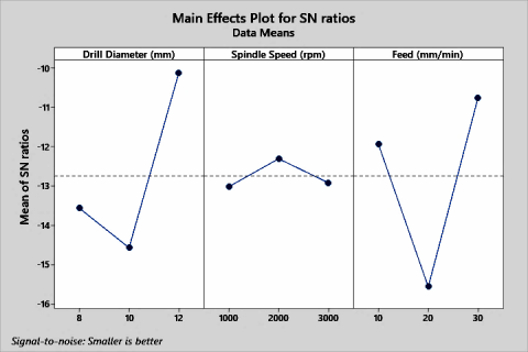
From Figure 9 it is found that the surface roughness is minimum at the parameter levels of drill diameter level 3 (12 mm), Feed Rate level 3 (30 mm/min) and Speed of spindle level 2 (2000 rpm). The response Table 4 give the rank order, that gives the order of which the surface roughness will mostly affected. The response table gives the parameter rank which is having the higher impact on the surface roughness. Table 4 indicates that feed rate is having a highest impact on the surface roughness, drill diameter is having moderate impact and spindle speed is having less impact.
Table 5. ANOVA for surface roughness
|
Source |
DF |
Seq SS |
Adj SS |
Adj MS |
F-Value |
% Contribution |
|
Drill Diameter (mm) |
2 |
6.4758 |
6.4758 |
3.23788 |
3.32 |
35.08 |
|
Spindle Speed (rpm) |
2 |
0.1014 |
0.1014 |
0.05071 |
0.05 |
0.55 |
|
Feed Rate (mm/min) |
2 |
9.9311 |
9.9311 |
4.96554 |
5.09 |
53.80 |
|
Error |
2 |
1.9494 |
1.9494 |
0.97471 |
|
10.56 |
|
Total |
8 |
18.4577 |
|
|
|
|
Figure 9. Main effect plot for surface roughness
The F-test clearly reveals that drill diameter and feed rate having crucial impact on surface roughness. From the ANOVA Table 5, it can also be known how much contribution does a parameter causing effect. The results shows that the feed rate has high contribution of 53.80%, whereas the diameter of drill and speed of spindle having the contributions in the order 35.08%, 0.55%.
5.2 Influence of input factors on delamination factor
The response Table 6 for S/N ratio for delamination factor and corresponding analysis variance is acquired by the software Minitab 19. The computation of S/N ratio follows the ‘Smaller the best model’.
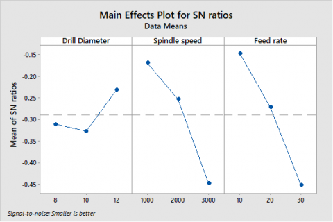
From the Table 6, the rank of the parameters can be find according to the impact they do on the delamination. The results show that the feed rate and speed of spindle has the greater impact on the delamination than the drill diameter.
The Figure 10 gives the information about the delamination according to the change in the levels of the parameters and help to determine the optimum combination parameter for the lesser delamination effect. From the plot it is observed that the parameter will get optimized at diameter of drill at level 3 (12 mm), speed of spindle at level 1 (1000 rpm), feed rate at level 1 (10 mm).
The F-Test reveals that the speed of spindle and feed rate have greater influence on delamination. From the Table 7 of ANOVA, it can also be known how much contribution does a parameter causing effect. The results shows that the feed rate has greater contribution of 59.86%, whereas the speed of spindle and the diameter of drill having the contributions in the order 24.98% and 5.10%.
Table 6. Response table for S/N ratio of delamination factor
|
Level |
Drill Diameter (mm) |
Spindle Speed (rpm) |
Feed rate (mm/min) |
|
1 |
-0.3113 |
-0.1689 |
-0.1463 |
|
2 |
-0.3272 |
-0.2532 |
-0.2714 |
|
3 |
-0.2318 |
-0.4483 |
-0.4526 |
|
Delta |
0.0954 |
0.2794 |
0.3062 |
|
Rank |
3 |
2 |
1 |
Figure 10. Main effect plot for delamination
5.3 Grey relational analysis
The transformation of original sequence to S/N ratio was the initial step in GRA. Equation 5 utilized for ‘smaller the best’ for both the Delamination and Surface Roughness. On the basis of S/N ratio the analysis was carried out and are shown in the Table 8 and the normalized values are shown in Table 9, determined by the equation and the reference and deviation sequences used for determining the grey grade are depicted in Table 10.
The relational degree for dominant parameter and other parameters is computed associated with all performance characteristics by using the value GRG and corresponding GRG rank as shown in Table 11. The higher values of GRG tend to achieve the goal of analysis.
Table 7. ANOVA for delamination
|
Source |
Degrees of Freedom |
Seq SS |
Adj SS |
Adj MS |
F-Value |
% Contribution |
|
Drill Diameter |
2 |
0.000193 |
0.000193 |
0.000096 |
0.50 |
5.10 |
|
Spindle Speed |
2 |
0.000942 |
0.000942 |
0.000471 |
2.45 |
24.98 |
|
Feed rate |
2 |
0.002265 |
0.002265 |
0.001132 |
5.89 |
59.86 |
|
Error |
2 |
0.000384 |
0.000384 |
0.000192 |
|
10.16 |
|
Total |
8 |
0.003784 |
|
|
|
100 |
Table 8. S/N ratio of output parameters
|
S. No |
Drill Diameter(mm) |
Spindle Speed (rpm) |
Feed rate (mm/min) |
S/N ratio Delamination |
S/N ratio Surface Roughness |
|
1 |
8 |
1000 |
10 |
-0.6926 |
-14.2361 |
|
2 |
8 |
2000 |
20 |
-1.0076 |
-16.3248 |
|
3 |
8 |
3000 |
30 |
-0.6039 |
-10.1030 |
|
4 |
10 |
1000 |
20 |
-0.9688 |
-16.0143 |
|
5 |
10 |
2000 |
30 |
-0.6039 |
-13.3491 |
|
6 |
10 |
3000 |
10 |
-0.5225 |
-14.3201 |
|
7 |
12 |
1000 |
30 |
-0.5714 |
-8.7867 |
|
8 |
12 |
2000 |
10 |
-0.7883 |
-7.2346 |
|
9 |
12 |
3000 |
20 |
-0.6926 |
-14.3201 |
Table 9. Normalized values of output parameters
|
S. No |
Drill Diameter |
Spindle Speed |
Feed Rate |
Delamination |
SR |
|
1 |
8 |
1000 |
10 |
0.6557 |
0.3294 |
|
2 |
8 |
2000 |
20 |
0.0000 |
0.0000 |
|
3 |
8 |
3000 |
30 |
0.8361 |
0.7882 |
|
4 |
10 |
1000 |
20 |
0.0820 |
0.0541 |
|
5 |
10 |
2000 |
30 |
0.8361 |
0.4471 |
|
6 |
10 |
3000 |
10 |
1.0000 |
0.3176 |
|
7 |
12 |
1000 |
30 |
0.9016 |
0.8941 |
|
8 |
12 |
2000 |
10 |
0.4590 |
1.0000 |
|
9 |
12 |
3000 |
20 |
0.6557 |
0.3176 |
Table 10. Grey relational sequence and coefficient values of output parameters
|
S. No |
Drill Diameter (mm) |
Spindle Speed (rpm) |
Feed Rate (mm/min) |
Grey Relational Sequence |
Grey Relational Coefficient |
||
|
Delamination |
SR |
Delamination |
SR |
||||
|
1 |
8 |
1000 |
10 |
0.34426 |
0.67059 |
0.59223 |
0.42714 |
|
2 |
8 |
2000 |
20 |
1.00000 |
1.00000 |
0.33333 |
0.33333 |
|
3 |
8 |
3000 |
30 |
0.16393 |
0.21176 |
0.75309 |
0.70248 |
|
4 |
10 |
1000 |
20 |
0.91803 |
0.94588 |
0.35260 |
0.34581 |
|
5 |
10 |
2000 |
30 |
0.16393 |
0.55294 |
0.75309 |
0.47486 |
|
6 |
10 |
3000 |
10 |
0.00000 |
0.68235 |
1.00000 |
0.42289 |
|
7 |
12 |
1000 |
30 |
0.09836 |
0.10588 |
0.83562 |
0.82524 |
|
8 |
12 |
2000 |
10 |
0.54098 |
0.00000 |
0.48031 |
1.00000 |
|
9 |
12 |
3000 |
20 |
0.34426 |
0.68235 |
0.59223 |
0.42289 |
Table 11. Grey grade and rank for values of output parameters
|
S. No |
Drill Diameter |
Spindle Speed |
Feed Rate |
Grey Relational Grade |
||
|
GRG total |
GRG |
GRG rank |
||||
|
1 |
8 |
1000 |
10 |
1.01936869 |
0.254842172 |
6 |
|
2 |
8 |
2000 |
20 |
0.66666667 |
0.166666667 |
9 |
|
3 |
8 |
3000 |
30 |
1.45556576 |
0.36389144 |
3 |
|
4 |
10 |
1000 |
20 |
0.69841076 |
0.174602689 |
8 |
|
5 |
10 |
2000 |
30 |
1.22794675 |
0.306986689 |
5 |
|
6 |
10 |
3000 |
10 |
1.42288557 |
0.355721393 |
4 |
|
7 |
12 |
1000 |
30 |
1.66085916 |
0.415214789 |
1 |
|
8 |
12 |
2000 |
10 |
1.48031496 |
0.37007874 |
2 |
|
9 |
12 |
3000 |
20 |
1.01511858 |
0.253779645 |
7 |
Table 12. Response and effect of parameters on GRG
|
Drill diameter (D) |
Spindle Speed (S) |
Feed rate (F) |
|
|
Level-1 |
0.2618 |
0.2816 |
0.3269 |
|
Level-2 |
0.2791 |
0.2812 |
0.1983 |
|
Level-3 |
0.3464 |
0.3245 |
0.3620 |
|
Delta (Max-Min) |
0.0846 |
0.0432 |
0.1637 |
|
Rank |
2 |
3 |
1 |
Table 13. ANOVA for grey grade verses input parameters
|
Source |
DF |
Adj SS |
Adj MS |
F-Value |
% Contribution |
|
Drill diameter |
2 |
0.011973 |
0.005986 |
4.42 |
19.23 |
|
Spindle Speed |
2 |
0.003709 |
0.001855 |
1.37 |
5.89 |
|
Feed rate |
2 |
0.044547 |
0.022274 |
16.45 |
70.78 |
|
Error |
2 |
0.002708 |
0.001354 |
4.30 |
|
|
Total |
8 |
0.062937 |
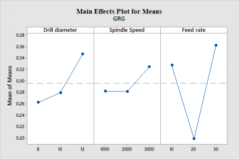
Table 12 shows the mean value of the GRG for each level of the input characteristics and the response graph Figure 11 in order to choose the optimal sequence of parameters for proper machining. Table 12 resembles that effect of feed rate machining parameter is more effective than all other parameters. The Feed rate influences more and the drill diameter is next to feed rate in producing the multi characteristics surface roughness and delamination.
Figure 11. Response graph of the total means
Figure 11 and Table 12 shows the response graph and the response table respectively to find the optimum process parameters which has minimum delamination factor and minimum surface roughness. The optimum process parameters obtained are drill diameter at 12 mm, speed of spindle at 3000 rpm, feed rate at 30 mm/min.
Table 13 shows the ANOVA for the mean of GRG which indicates that the contribution among the three parameters for minimum delamination factor and minimum surface roughness. The highest contribution is the feed rate which accounts about 70.78%, whereas the spindle speed and drill diameters having the contributions in the order 5.89% and 19.23%.
In this work impact of three machining parameters such as diameter of drill, feed rate and speed of spindle on surface roughness and delamination of glass/hemp/bamboo fibres based hybrid composites are studied using ANOVA and GRA. The following inferences are made from the above research work:
The optimization methodology developed in this research is useful to enhance various performance characteristics in drilling of glass fibre embedded hybrid composites.
[1] Kilickap, E. (2010). Optimization of cutting parameter of delamination based on Taguchi method during drilling on GFRP composite. Expert Systems with Applications, 37(8): 6116-6122. https://doi.org/10.1016/j.eswa.2010.02.023
[2] Murthy, B., Lewlyn, L.R., Rodrigues. (2013). Process parameters optimization using Taguchi and RSM to minimize the damage in the drilling of GFRP composites. International Journal of Earth Sciences and Engineering, 6(4): 842-846.
[3] Othman, A.R., Hassan, M.H., Abu Bakar, E., Othman, W.A.F.W. (2018). Statistical analysis of the machining parameters in drilling of carbon fibre reinforced plastics (CFRP) composite with various drill types. In Intelligent Manufacturing & Mechatronics, pp. 141-154. https://doi.org/10.1007/978-981-10-8788-2_14
[4] Hocheng, H., Tsao, C. (2003). Comprehensive analysis of delamination in drilling of composite material with various drill bits. Journal of Materials Process Technology, 140(1-3): 335-339. https://doi.org/10.1016/S0924-0136(03)00749-0
[5] Babu, J., Sunny, T. (2013). Optimization of process parameters in drilling of GFRP composites drilled by an end mill. International Journal of Recent Development in Engineering and Technology, 1(1): 16-23.
[6] Ramesh, M., Sudharsan, P., Palanikumar, K. (2015). Processing and mechanical property evaluation of flax glass fiber reinforced polymer composites. Applied Mechanics and Materials, 766-767: 144-149. https://doi.org/10.4028/www.scientific.net/AMM
[7] Singh, I., Bhatnagar, N. (2006). Drilling of unidirectional glass fiber reinforced plastic (UD-GFRP) composite laminates. The International Journal of Advanced Manufacturing Technology, 27(9-10): 870-876. https://doi.org/10.1007/s00170-004-2280-7
[8] Babu, G.D., Babu, K.S., Gowd, B. (2013). Optimization of machining parameters in drilling hemp fiber reinforced composites to maximize the tensile strength using design experiments. https://doi.org/10.3365/KJMM.2013.51.10.719
[9] Ramesh, M., Gopinath, A. (2017). Measurement and analysis of thrust force in drilling sisal-glass fiber reinforced polymer composites. IOP Conference Series: Materials Science and Engineering, 197(1): 1-7. https://doi.org/10.1088/1757-899X/197/1/012056
[10] Kaybal, H.B., Ünüvar, A., Koyunbakan, M., Avcı, A. (2019). A novelty optimization approach for drilling of CFRP nanocomposite laminates. The International Journal of Advanced Manufacturing Technology, 100(9): 2995-3012. https://doi.org/10.1007/s00170-018-2873-1
[11] Khan, Z.A., Siddiquee, A.N., Kamaruddin, S. (2012). Optimization of In-feed centreless cylindrical grinding process parameters using grey relational analysis. J. Science and Technology, 20: 257-268.
[12] Ramanujam, R., Muthukrishnan, N., Raju, R. (2011). Optimization of cutting parameters for turning Al-SiC(10p) MMC using ANOVA and grey relational analysis. International Journal of Precision Engineering and Manufacturing, 12: 651-656. https://doi.org/10.1007/s12541-011-0084-x