Ayoub Laoucine | Mourad Bachene | Saïd Rechak | Giulio Lorenzini* | Noureddine Kaid | Younes Menni
© 2022 IIETA. This article is published by IIETA and is licensed under the CC BY 4.0 license (http://creativecommons.org/licenses/by/4.0/).
OPEN ACCESS
In this work, a numerical study of the perforation of 6061-T6 aluminum, Titanium Ti6Al4V and stainless steel (Nitronic33) plates by a rigid flat nose punch is carried out. The Johnson-Cook model was used to define the behavior of the material constituting the plate. This homogeneous behavior was coupled with the Johnson-Cook rupture criterion to completely predict the perforation process. Initially, the present results are validated by comparing them with the results reported in the literature, including those obtained from experimental work. Thereafter, several numerical parametric analyses are performed to investigate the behavior of these metal plates depending on the maximum breaking force, the temperature in the perforated plates, the kinetic energy, the clearance on the shape of the sheared edge, and the dimensional accuracy of the plates.
punch, perforation, numerical simulation, thermo-viscoplastic, punching
Punching is closed form shearing. It is a sliding of metal in a transverse plane between two bars, that they deform without ceasing to be parallel. In the literature, different names, such as ‘dynamic punching test’ [1] and ‘fine cutting process’ [2], ‘shear-compression’ [3] can be found as descriptions of this method of analysis. Unblocking the hole is performed using a punch, under compressive load is applied to the material of a disc-shaped specimen is placed on a die. Movement of the punch causes shear stresses at the interface and sample breakage within the gap between the punch and the die. The punch and the die, two tools comparable to shear blades must have very high mechanical properties in order to resist the forces resulting from penetration. Sheet metal punching has been the subject of several research works for decades and plays an important role in industry and is commonly used to mass produce components for industries such as aerospace and automotive manufacturing. The sheared surface quality depends on several process parameters such as the cutting speed, the penetration force, the sharpness of the edge of the punch and the die, the temperature and the clearance between the punch and the die [4, 5]. Golovashchenko et al. [6] find that the cutting clearances play an important role in the extensibility of the sheared edges and the height of the burrs in the sheet. Zeidi et al. [7] used the technique of light microscopy to study micro-structural details of punch and plaque damage. In the case of the numerical simulation of the cutting process such as punching or shearing, the needs expressed by the industry concerning the reliability and speed of the simulations, require the development of theoretical and numerical models making it possible to reproduce the operation of formatting. In this context, the application of finite element models using damage models facilitates and improves these predictions. Schmitz et al. [3] used the constitutive model considered is that proposed by Johnson [8] for the adiabatic cutting of high strength steels and found that the numerical modeling satisfactorily predicts the characteristic shape of the cut edge. Dabboussi and Nemes [1] determined the constituent parameters of the Johnson-Cook model and, simplified, of the failure model for three materials 6061-T6 aluminum, titanium Ti-6Al-4V and stainless steel reinforced with nitrogen (Nitronic 33) and show that the simplified failure model proved to be adequate for aluminum and titanium, it was not possible to conclude the same for (Nitronic 33) due to the intrinsic characteristics of this material and multiplicative form of the Johnson-Cook model. Hambli [9] and Isik et al. [10] used the damage model of Lemaitre [11], which based on the thermodynamics of irreversible processes to simulate fine cutting. Hambli [9] showed that the Lemaitre model [11] is unable to model the process of fine cutting of sheets of 4mm thick and suggested that the application of the model of Rice and Tracey [12] offers a better prediction of the l initiation and propagation of cracks. On the contrary, Hambli [13] showed that Lemaitre's model offers a better prediction of the slicing process, compared to Gurson's model [14] for a relatively thick sheet (3.5 mm sheet thickness). Bacha et al. [15] controlled the crack path by stress and strain fields in the punch-die area and the damage parameter is based on the accumulated plastic stress. Sahli et al. [16] used the commercial code Lsdyna to predict the distribution of shear stress and plastic deformation during cutting and in the shear zone of a steel sheet (16MnCr5) of 4.6 mm thick relative to the punch-die clearance and found that the numerical results of the validation simulations were in agreement with the experimental data with an approximate margin of error of 31%. Krobath et al. [17] Predict the tool loads in a fine cutting process by numerically simulating the tensile stresses in fine cutting punches on a two-dimensional model and taking into account the elastic stresses of the tool is necessary. Several important studies have been done recently in the same context as shown in the following indexed papers [18-25].
In this work, the perforation of metal plates by high speed impact is treated for three materials 6061-T6 aluminum, Ti-6Al-4V titanium and Nitrogen reinforced stainless steel (Nitronic 33). The operation is performed by a punch with a flat nose. The damage model is based on the Johnson criterion [8]. The resolution is carried out numerically using the ANSYS AUTODYN software and in order to compare the results found with the experimental and numerical results of Dabboussi and Nemes [1]. At the end of this study, we make predictions by numerical simulation the influence of the clearance on the shape of the sheared edge of the part for the three treated metals (Nitronic33 of 1 mm and 1.5mm thick, aluminum AL6061T6 of 2mm and 3mm thick, and Titanium Ti6AL4V of 1mm and 1.5mm thick).
The constitutive law used is that based on the Johnson model [8], this model which was developed for the problems of impact and penetration, takes into account the plastic deformations, the deformation speeds, and the deformation temperature, its general shape is given by the equation:
$\sigma_{e q}=\left[A+B p^{n}\right]\left[1+C \ln \dot{p}^{*}\right]\left[1-T^{* m}\right]$ (1)
where, $A, B, C, m$, and $n$ are the material constants, which are provided from experimental data. $A$ the yield stress; $B$ the hardening module; $C$ the strain rate sensitivity; $\varepsilon$ the equivalent plastic strain; $n$ the coefficient of hardening; $\dot{\varepsilon}^{*}=$$\frac{\dot{\varepsilon}}{\varepsilon_{0}}$ the normalized strain rate; $\dot{\varepsilon}$ the strain rate; $\dot{\varepsilon}_{0}$ normalizing reference strain rate; $m$ the temperature sensitivity parameter; $T^{*}$ the homologous temperature given by $T^{*}=\left(\mathrm{T}_{\text {inst }}-T_{\text {room }}\right) /$ (T melt $\left.-T_{\text {room }}\right) ; T_{j a s s t}$ the instantaneous temperature; $T_{\text {room }}$ the room temperature; and $T_{\text {melt }}$ is the melting temperature of the material.
The numerical values of the constants described previously are reported in Table 1. These values were also used by Dabboussi and Nemes [1], with $\dot{p}_{0}=1$ and $m=1$.
Table 1. Constants of the constitutive equation
|
Materials |
A (MPa) |
B (MPa) |
n |
C |
M |
|
Nitronic33 |
446 |
2075 |
0.84 |
0.05 |
1 |
|
Aluminum 6061-T6 |
335 |
85 |
0.11 |
0.012 |
1 |
|
Titanium Ti6AL4V |
1050 |
955 |
0.63 |
0.011 |
1 |
The transition temperature is taken equal to the ambient temperature. The fracture model used is extended from the Johnson [8] formulation; it takes into account the plastic strain $\bar{\varepsilon}^{p}$, the plastic strain rate $\overset{\cdot }{\mathop{{{{\bar{\varepsilon }}}^{p}}}}\,$, and the temperature T. Its general form is given by:
$D\left( {{{\bar{\varepsilon }}}^{p}},\overset{\cdot }{\mathop{{{{\bar{\varepsilon }}}^{p}}}}\,,T,\sigma * \right)=\sum{\left( \frac{\Delta {{{\bar{\varepsilon }}}^{p}}}{\bar{\varepsilon }_{f}^{p}\left( \overset{\cdot }{\mathop{{{{\bar{\varepsilon }}}^{p}}}}\,,T,{{\sigma }^{*}} \right)} \right)}$ (2)
with $D$ is the sum of all the strain increments; $\Delta \bar{\varepsilon}^{\mathrm{p}}$ the increment of the equivalent plastic strain, which occurs during a cycle of integration; and $\bar{\varepsilon}_{f}^{p}$ is the level of the critical strain, defined as follows:
$\bar{\varepsilon }_{f}^{p}=\left[ {{D}_{1}}+{{D}_{2}}\exp \left( {{D}_{3}}{{\sigma }^{*}} \right) \right]\left[ 1+{{D}_{4}}\ln \left( \frac{\overset{\cdot }{\mathop{{{{\bar{\varepsilon }}}^{p}}}}\,}{{{{\dot{\varepsilon }}}_{0}}} \right) \right]\left[ 1+{{D}_{5}}{{T}^{*}} \right]$ (3)
$\sigma^{*}=\sigma_{m} / \bar{\sigma}$ (4)
$\sigma^{*}=\frac{1}{3 \bar{\sigma}}\left(\sigma_{1}+\sigma_{2}+\sigma_{3}\right)$ (5)
with $\sigma_{m}$ is the average stress; and $D_{i}$ represents the fracture constants depending on the material used [1]. These constants are shown in Table 2 .
Table 2. Constants of formula (3) [1]
|
Materials |
D1 |
D2 |
D3 |
D4 |
D5 |
|
Nitronic33 |
0.52 |
0 |
0 |
0.05 |
0 |
|
Aluminum 6061-T6 |
1.15 |
0 |
0 |
0 |
0 |
|
Titanium Ti6AL4V |
0.8 |
0 |
0 |
0 |
0 |
The numerical resolution of the perforation problem is carried out using the ANSYS AUTODYN-2D code. The simulations are based on the experimental device proposed by Dabboussi and Nemes [1], namely
So, for the material of the plate, three shades are considered; Aluminum 6061-T6, TitaniumTi6Al4V and Stainless Steel (Nitronic33).
The coefficient of the friction force used in this work varies from 0.05 to 0.3.
The plate and the punch were discretized with the four-node Lagrange element. The mesh was refined in the zone of punch-plate contact because on this zone the strains are concentrated. Figure 1 represents a view of the punch-die axisymmetric mesh.
Figure 1. Modeling of the punch-plate contact
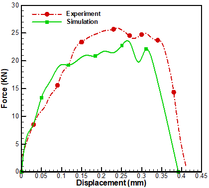
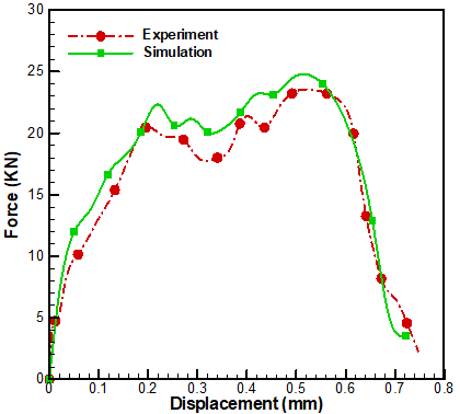
The results relating to the variation of the penetration force as a function of displacement of the punch are shown in Figure 2. In the simulation, the punch speed is taken equal to 20 m/s. The results are obtained for three cases of materials; (a) Aluminum alloys 6061T6, (b) TitaniumTi6AL4V, and (c) Nitronic33. The results are also compared with those of the experimental ones which reported by Dabboussi and Nemes [1]. As can be observed from Figure 2, our results agree well with the reported experimental results. For the Nitronic33 plates, the maximum load is approximately 24.31kN for a sheet of 1mm thickness, and approximately 35.9kN for a sheet of 1.5mm thickness.
(a) Aluminium 6061-T6 plate 2 mm thick
(b) Aluminium 6061-T6 plate 3 mm thick
(c) Titanium Ti6AL4V plate 1 mm thick
(d) Titanium Ti6AL4V plate thickness of 1.5 mm
(e) Plate Nitronic33 of 1 mm thick
(f) Plate Nitronic33 thickness of 1.5 mm
Figure 2. Variation of the penetration force as a function of displacement
These values correspond to a penetration punch of 0.75mm and 0.78mm, respectively which are very close to that found experimentally by Dabboussi and Nemes [1] (estimated at 23.56KN with a penetration of 0.74mm for a sheet of 1mm thick and estimated at 34.59KN with a penetration of 0.75mm for a sheet 1.5mm thick). As for Aluminum 6061T6, the maximum penetration force is around 16.65kN, this indicate that the Aluminum 6061T6 material is the most ductile compared to the other two materials, which can give a failure displacement equal to 1.03mm for a sheet of 2mm thick.
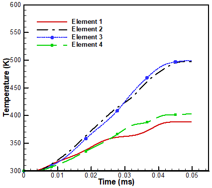
Figure 3. Experimental and simulation punch energy
(a) The plate 1 mm thick Nitronic 33
(b) The 2mm thick aluminum plate AL6061T6
(c) The plate 1 mm thick Titanium Ti6Al4V
Figure 4. Temperature estimate in the cutting area
For a more precise comparison, the next comparison study is done by examining the energy of the punch. Figure 3 estimate of the maximum energy of the cut for the three material cases, this energy can be evaluated from the kinetic energy of the punch. On same figure we also report the experimental results of Dabboussi and Nemes [1]. It is clear that the results of the present study are in good agreement with those of the experimental one. It is also observed that the Nitronic33 requires more cutting energy compared to the other two materials.
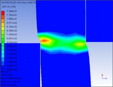
Figure 4 shows the change in temperature along the shear band line as a function of time. The elements on which the temperature is measured are indicated in Figure 4. The obtained results show that there is a significant increase in the temperature inside the plates for the three types of metals. The temperature reaches its maximum on the elements at the end of contact with the punch; on the other hand on the elements inside the shear band and at the end of contact with the die, the temperature drops. This phenomenon is clearly visible in the case of plates made of Nitronic33 and Titanium Ti6AL4V.
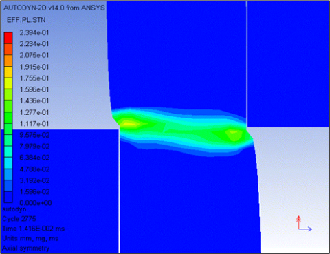
(a) 1.5 mm thick titanium
(b) 1 mm thick titanium
(c) Aluminum AL6061T6 3 mm thick
(d) Aluminum AL6061T6 2 mm thick
(e) Nitronic33 de 1.5 mm thick
(f) Nitronic33 de 1mm thick
Figure 5. Details of the crack propagation during the penetration of the punch with a speed of 20 m/s
Figure 5 shows the failure modes that are observed during the perforation operation of plates made with Titanium Ti6AL4V for a perforation speed equal to 20m/s. It is observed that the opening of the adiabatic shear band appears very quickly in other words it appears after a few microseconds of contact. The very high impact velocity also leads to the appearance of adiabatic shear bungs.
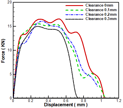
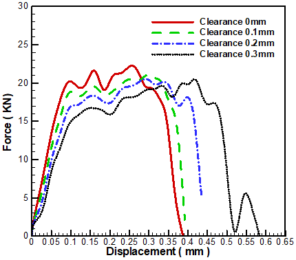
Figure 6 presents the force-displacement curves obtained by the punching simulation of plates with different metal types (AL6061-T6 Aluminum, Titanium Ti6AL4V and Nitronic33). In order to consider the effect of the clearance on the cutting process the simulation is carried out with punch speed of 20m/s and with a different clearance between the punch and the die. It can be seen form the figure the simulation results show that the effect of the clearance on the cutting force is very weak such that an increase in play between the punch and die from 0 mm to 0.3 mm causes a decrease in the cutting force for all three metal types, also the increased backlash leads to an increased breaking displacement for Titanium Ti6AL4V and nitronic33 (1mm plate thickness).
(a) Aluminium 6061-6T plate 2 mm thick
(b) Titanium Ti6AL4V plate 1 mm thick
(c) Plate Nitronic33 of 1 mm thick
Figure 6. Force-displacement curves for different Punch-die clearances
For example, as reported on Figure 7, when the clearance is zero, the punch displacement for the total rupture of the Titanium plate is 0.387 mm, and the breaking displacement increases by about 30% and becomes 0.584 mm and on the other hand, increasing the clearance from 0 to 0.3mm reduces the penetration of the perforation for the overall breakage of the aluminum plate AL6061-T6 (2mm thick).
(a) Punch-die Clearance of 0 mm for aluminium
(b) Punch-die Clearance of 0.3 mm for Titanium
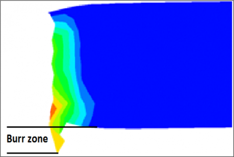
Figure 7. Shape defects on the sheared surface
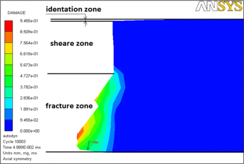
Figure 8 illustrates the results obtained by the simulations shows the essential influence of the clearance on the shape of the sheared edge and the dimensional accuracy of the part for the three considered metals (Nitronic33 of 1 mm and 1.5mm thick, d (2mm and 3mm thick AL6061T6 aluminum, and 1mm and 1.5mm thick Titanium Ti6AL4V). It can be observed that the punch-die clearance played a central role in influencing the quality of the sheared surface and work piece shape for the three sheared metals. As shown in Figure 7 the sheared blunder of the cut piece can have four zones, the identification zone, the burnishing zone, the fracture zone, and a burr zone.
We note the appearance of this last zone. in only one case in this study, and this happened in the 1mm thick Titanium sheet for a 0.3mm punch-die (see Figure 7).
As expected, for the case of a cutting gap of 0.3 mm the work piece boundary profile causes a poor cutting quality, and that is due to the presence of large edge identification and longer burrs. For Titanium plates a clearance of 0.2 mm is acceptable, in these cases the decrease in the clearance leads to the appearance of a large fracture zone (see Fig. 8a and 8b). It has also been observed that plates with aluminum is are very sensitive to the cutting clearance: the height of the fracture zone decreases as the cutting clearance increases, for example the height of the area of equal fraction of about 68% of the thickness of the plate for the punch-die clearance to be zero, this percentage decreases to 7% for a clearance of 0.3 mm and it is noted that this clearance is acceptable in these cases (see Figure 8c and 8d).
For the Nitronic33 a higher deformation in the profile of the work piece boundary are observed in the range of cutting clearances from 0mm to 0.3mm, this is due to the presence of a large edge identification Figure 8e.
(a) Titanium sheet of 1mm thick
(b) Titanium sheet of 1.5mm thick
(c) Aluminium sheet of 2mm thick
(d) Aluminium sheet of 3mm thick
(e) Nitronic33 sheet of 1.5mm thick
Figure 8. Deformities on the sheared surface for different punch-die clearance
The perforations of Titanium Ti6AL4V, Nitronic33 and Aluminum 6061-T6 plates at high speed are investigated for different plates’ thickness. The plates are impacted by a rigid flat nose punch at an angle equal to 90°. The finite element simulations were carried out using axial symmetry in the ANSYS-AUTODYN software; the essential points that can be observed from this study are summarized as follows:
The results of the present study are in good agreement with the experimental results published in the literature [1].
The Johnson-Cook failure criterion are effective for punching the three plate sheet types (aluminum, titanium and Nitronic33).
Results show a significant increase in temperature of the punch plate zone for a punch speed of 20 m/s.
Results reveled that part of the energy is absorbed by the punch; and the rest is absorbed by the deformation of the plate.
It is observed that the adiabatic shear band appears quickly after a few microseconds of contact.
The effect of the clearance on the cutting force is very small, in other words an increase in the clearance between the punch and die from 0mm to 0.3mm lead to a decrease in the cutting force for the three metal types.
The punch-die clearance played a central role in influencing the quality of the sheared surface the shape, and the dimensional accuracy of the part for the three metal types.
From a practical point of view numerical simulations are more cost effective than using physical prototypes which can be used to find optimal parameters for the punching process. Numerical simulation can also provide useful information on the surface quality of edges after punching.
[1] Dabboussi, W., Nemes, J.A. (2005). Modeling of ductile fracture using the dynamic punch test. International Journal of Mechanical Sciences, 47(8): 1282-1299. https://doi.org/10.1016/j.ijmecsci.2005.01.015
[2] Cockcroft, M.G. (1968). Ductility and workability of metals. J. of Metals., 96: 2444.
[3] Schmitz, F., Winter, S., Clausmeyer, T., Wagner, M.F. X., Tekkaya, A.E. (2020). Adiabatic blanking of advanced high-strength steels. CIRP Annals, 69(1): 269-272. https://doi.org/10.1016/j.cirp.2020.03.007
[4] Faura, F., Garcıa, A., Estrems, M. (1998). Finite element analysis of optimum clearance in the blanking process. Journal of Materials Processing Technology, 80-81: 121-125. https://doi.org/10.1016/S0924-0136(98)00181-2
[5] Fang, G., Zeng, P., Lou, L. (2002). Finite element simulation of the effect of clearance on the forming quality in the blanking process. Journal of Materials Processing Technology, 122(2-3): 249-254. https://doi.org/10.1016/S0924-0136(02)00056-0
[6] Golovashchenko, S., Zhou, W., Nasheralahkami, S., Wang, N. (2017). Trimming and sheared edge stretchability of light weight sheet metal blanks. Procedia Engineering, 207: 1552-1557. https://doi.org/10.1016/j.proeng.2017.10.1077
[7] Zeidi, A., Saada, F. B., Elleuch, K., Atapek, H. (2021). On the failure of punching process. Engineering Failure Analysis, 120: 105035. https://doi.org/10.1016/j.engfailanal.2020.105035
[8] Johnson, G.R. (1983). A constitutive model and data for materials subjected to large strains, high strain rates, and high temperatures. Proc. 7th Inf. Sympo. Ballistics, pp. 541-547.
[9] Hambli, R. (2001). Finite element simulation of fine blanking processes using a pressure-dependent damage model. Journal of Materials Processing Technology, 116(2-3): 252-264. https://doi.org/10.1016/S0924-0136(01)01009-3
[10] Isik, K., Yoshida, Y., Chen, L., Clausmeyer, T., Tekkaya, A.E. (2018). Modelling of the blanking process of high-carbon steel using Lemaitre damage model. Comptes Rendus Mécanique, 346(8): 770-778. https://doi.org/10.1016/j.crme.2018.05.003
[11] Lemaitre, J. (1985). A continuous damage mechanics model for ductile fracture. J. Eng. Mater. Technol., 107(1): 83-89. https://doi.org/10.1115/1.3225775
[12] Rice, J.R., Tracey, D.M. (1969). On the ductile enlargement of voids in triaxial stress fields∗. Journal of the Mechanics and Physics of Solids, 17(3): 201-217. https://doi.org/10.1016/0022-5096(69)90033-7
[13] Hambli, R. (2001). Comparison between Lemaitre and Gurson damage models in crack growth simulation during blanking process. International Journal of Mechanical Sciences, 43(12): 2769-2790. https://doi.org/10.1016/S0020-7403(01)00070-4
[14] Gurson, A.L. (1977). Continuum theory of ductile rupture by void nucleation and growth: Part I—Yield criteria and flow rules for porous ductile media. J. Eng. Mater. Technol., 99(1): 2-15. https://doi.org/10.1115/1.3443401
[15] Bacha, A., Daniel, D., Klocker, H. (2010). Crack deviation during trimming of aluminium automotive sheets. Journal of Materials Processing Technology, 210(14): 1885-1897. https://doi.org/10.1016/j.jmatprotec.2010.06.023
[16] Sahli, M., Roizard, X., Colas, G., Assoul, M., Carpentier, L., Cornuault, P.H., Giampiccolo, S., Barbe, J.P. (2020). Modelling and numerical simulation of steel sheet fine blanking process. Procedia Manufacturing, 50: 395-400. https://doi.org/10.1016/j.promfg.2020.08.072
[17] Krobath, M., Klünsner, T., Ecker, W., Deller, M., Leitner, N., Marsoner, S. (2018). Tensile stresses in fine blanking tools and their relevance to tool fracture behavior. International Journal of Machine Tools and Manufacture, 126: 44-50. https://doi.org/10.1016/j.ijmachtools.2017.12.005
[18] Yousefi, M., Pervaiz, S. (2022). 3D Finite element modeling of wear effects in the punching process. Simulation Modelling Practice and Theory, 114: 102415. https://doi.org/10.1016/j.simpat.2021.102415
[19] Zakeri, M., Mansoori, H., Sadeghian, M., Guagliano, M. (2022). Impact response of fiber metal laminates based on aluminum and UHMWPE composite: Numerical simulation. Thin-Walled Structures, 172: 108796. https://doi.org/10.1016/j.tws.2021.108796
[20] Barik, S.K., Narayanan, R.G., Sahoo, N. (2022). Assessment of stress-strain constitutive models and failure models on the shock tube based impact forming of AA 5052-H32 sheet. Journal of Manufacturing Processes, 74: 573-591. https://doi.org/10.1016/j.jmapro.2021.12.047
[21] Lambiase, F., Grossi, V., Paoletti, A. (2022). High-speed joining of hybrid metal-polymer joints during the friction-assisted joining process. Composite Structures, 280: 114890. https://doi.org/10.1016/j.compstruct.2021.114890
[22] Jin, Y., Yu, H. (2022). Enhanced formability and hardness of AA2195-T6 during electromagnetic forming. Journal of Alloys and Compounds, 890: 161891. https://doi.org/10.1016/j.jallcom.2021.161891
[23] Wang, C., Wang, H., Shankar, K., Hazell, P.J. (2022). Dynamic failure behavior of steel wire mesh subjected to medium velocity impact: Experiments and simulations. International Journal of Mechanical Sciences, 216: 106991. https://doi.org/10.1016/j.ijmecsci.2021.106991
[24] Shao, Y., Li, X., Chen, L., He, E. (2022). New insights into fine equiaxed zone of laser-welded 2A97 Al-Li alloy. Journal of Alloys and Compounds, 895: 162717. https://doi.org/10.1016/j.jallcom.2021.162717
[25] Pang, Y., Yan, X., Qu, J., Wu, L. (2021). Dynamic response of polyurethane foam and fiber orthogonal corrugated sandwich structure subjected to low-velocity impact. Composite Structures, 114994. https://doi.org/10.1016/j.compstruct.2021.114994