Chenglong Ma
© 2021 IIETA. This article is published by IIETA and is licensed under the CC BY 4.0 license (http://creativecommons.org/licenses/by/4.0/).
OPEN ACCESS
Dry shrinkage and brittleness are outstanding problems with the concrete in road bridges. However, the road bridge concrete has not been systematically studied. No research has fully considered the influence of age on the physical-mechanical properties of road bridge concrete. There are few reports on how the green fiber dosage affects road bridge concrete. This paper analyzes the physical properties and durability of green fiber-reinforced concrete for road bridges (RBGFRC). Firstly, calculation methods were provided for physical-mechanical properties of RBGFRC, such as crack resistance, shear capacity of oblique section, and bending capacity of normal section. Next, the physical-mechanical properties of RBGFRC were investigated in terms of flexural strength, compressive strength, splitting tensile strength, and early cracking strength; the durability of the material was discussed from three aspects: carbonation resistance, resistance to freeze-thaw cycles, and porosity. Experimental results verify the good physical properties and durability of RBGFRC. The research provides a reference for applying RBGFRC in other scenarios.
green fiber, road bridges, concrete, physical-mechanical properties, durability
Cement concrete is the most widely used building material, thanks to its cheap price and low maintenance cost. But the material has deficiencies like weak tensile/compressive strength, poor cracking resistance, and low toughness [1-3]. Dry shrinkage and brittleness are outstanding problems with the concrete in road bridges. The components with seams also suffer from durability problems like rebar corrosion, strength degradation, surface cracking, and peeling, which arise from carbonation, chloride ion penetration, and multiple freeze-thaw cycles [4, 5]. To solve these problems, a common practice is to mix fibers into the concrete for road bridges.
The research on concrete has achieved many results. In cold regions, the promotion of pervious concrete requires full understanding of the frost resistance of the material [6-9]. Kim et al. [10] studied the change laws of strength and water permeability of pervious concrete reinforced by green fibers, under different diameters, lengths, dosages, and mixing modes, ranked these factors by degree of impact on porosity, permeation coefficient, and compressive strength, and optimized the value of each factor to maximize the concrete strength.
The mixing of fiberglass can effectively improve the corrosion, bending, and tensile resistances of concrete [11-15]. Noushini et al. [16] tested the compressive strength and splitting tensile strength of standard cubic samples of concrete with different fiberglass dosages, and discussed how the type and dosage of fiberglass affect the compressive strength, splitting strength, tensile strength, and fatigue life of fiberglass-reinforced concrete. Ragalwar et al. [17] carried out flexural and bending fatigue tests on fiberglass-reinforced concrete under three stress levels, drew stress-fatigue curves of the samples, constructed the log-log fatigue equation of fiberglass-reinforced concrete through Weibull distribution analysis, and accurately calculated the fatigue life and fatigue limit strength.
Concrete can be reinforced by various materials, including steel fibers, fiberglass, carbon fibers, and plant fibers [18-21]. To observe the varied effects of mixing different fibers, Bhosale et al. [22] applied damage theory and fiber reinforcement theory to examine how much and how fibers with different elastic moduli act on the dynamic mechanical properties of concrete, proposed a calculation method for tensile strength based on theories on composite materials and fiber spacing, and verified the reasonability of the method through impact tests.
The application scope of concrete is positively correlated with strength and durability. Currently, many scholars have researched the mechanism of fiber-reinforced concretes, and discussed how the fibers halt cracking and bridge up cracked surfaces [23-26]. Taking ultra-high-performance concrete as cement matrix, Bui et al. [27] explored the matching and design of fiber and cement matrix, quantified the orientation of crystal alignment, porosity, and hardness of fiber-cement interface based on the interface microstructure, and determine the optimal interface thickness and mix ratio between materials. Based on fiber orientation, type, and shape, De Brito et al. [28] analyzed the reinforcement effects of fibers on the strength and fracture performance of ultra-high-performance concretes of different grades, and optimized the matching between fiber and cement matrix in terms of size and grade.
Guided by theories on material compositing, green fiber-reinforced concrete for road bridges (RBGFRC) has attracted attention from scholars at home and abroad. However, the road bridge concrete has not been systematically studied. No research has fully considered the influence of age on the physical-mechanical properties of road bridge concrete. There are few reports on how the green fiber dosage affects road bridge concrete.
To bridge the gap, this paper analyzes the physical properties and durability of RBGFRC. Section 2 provides the calculation methods for physical-mechanical properties of RBGFRC, such as crack resistance, shear capacity of oblique section, and bending capacity of normal section. Through experiments, Section 3 investigates the physical-mechanical properties of RBGFRC in terms of flexural strength, compressive strength, splitting tensile strength, and early cracking strength. Combined with experimental results, Section 4 discusses the durability of the material from three aspects: carbonation resistance, resistance to freeze-thaw cycles, and porosity. Experimental results verify the good physical properties and durability of RBGFRC.
2.1 Calculation of crack resistance
The Code for Design of Concrete Structures (GB 50010-2010) gives the calculation formulas for crack control under extreme conditions for the reinforced concrete, prestressed concrete, and plain concrete suitable for houses and general structures during normal use. Let ωF be the crack resistance enhancement coefficient (CREC) of fibers of RBGFRC. Then, the relevant parameters can be adjusted by the said formulas. Let β denote the partial coefficient of concrete strength; e denote the beam section width; a denote the height of the compressive zone of concrete; gs denote the designed axial compressive strength concrete; gb* and gb denote the designed compressive and tensile strengths of rebar, respectively; Sc* and Sc be the section area of compressed and tensioned rebar, respectively. Then, we have:
${{\beta }_{1}}{{g}_{s}}ea+g_{b}^{*}S_{c}^{*}={{g}_{b}}{{S}_{c}}$ (1)
Let d0 be the effective height of road bridge; l be the distance from the point of composite compression on the rebar to the pressure boundary of rebar section. Then, the bending moment capacity of normal section CBho can be calculated by:
$C{{B}_{ho}}={{\beta }_{1}}{{g}_{s}}ea\left( {{d}_{0}}-\frac{a}{2} \right)+g_{b}^{*}S_{c}^{*}\left( {{d}_{0}}-l \right)$ (2)
Let Who be the crack load of original concrete road bridge. Then, the bending moment capacity of normal section CBho of original concrete road bridge can be calculated by:
$C{{B}_{ho}}=\frac{{{W}_{ho}}}{2}\times 0.36$ (3)
After determining the relevant parameters, it can be calculated that the Who belongs to 65-70kN, when the CBho of original concrete varies within 11-12kN·m.
Based on the provisions on the mix ratio of recycled aggregate in the Code for Design of Concrete Structures (DB11/T 803-2011), the relevant formulas on the carrying capacity of road bridge concrete mixed with 50% green fiber aggregate should be multiplied with a reduction coefficient of 70%. Then, the ultimate load Who falls in 45-50kN. The value of ωF depends on the crack load Wdl and maximum crack width θmax of green fibers.
Referring to the empirical formula on crack load in Chinese national standards and codes, the crack load Wdl of the concrete road bridge before mixing green fibers in actual conditions can be calculated by:
${{W}_{dl}}=\frac{{{W}_{ho}}}{3}$ (4)
Through actual tests on concrete road bridges before mixing green fibers, the measured crack load Wdl fell within 18-20kN, about 1/5 greater than theoretical calculation. It can be proved that theoretical crack load of RBGFRC is smaller than the actual value. For the crack safety of RBGFRC, the CREC ωF of fibers was fitted and adjusted by reducing the actual crack load of the road bridge by 1/4. Table 1 presents the ωF values calculated based on Who.
Table 1. ωF values calculated based on Who
|
Dosage |
0.6 |
1.2 |
1.8 |
2.4 |
3.0 |
3.6 |
4.2 |
|
ωF |
1.185 |
1.311 |
1.425 |
1.476 |
1.417 |
1.384 |
1.316 |
The crack load of concrete road bridges mixed with different types of green fibers can be calculated by similar methods. Comparing the actual crack load with calculated crack load, it is possible to obtain the crack resistance adjustment coefficient of the current type of RBGFRC, that is, the CREC ωF of fibers. To calculate the CREC ωF of fibers at different mix ratios, the relevant codes specify that the formulas on the carrying capacity of road bridge concrete mixed with 50% green fiber aggregate should be multiplied with a reduction coefficient of 70%. Based on the calculated ωF, the crack load of a fixed type of RBGFRC can be calculated by:
$W_{O-h o}=70 \% \times \omega_{F} \times W_{d l}$ (5)
Another important indicator of the crack resistance of RBGFRC is the maximum crack width. Let σR be crack expansion coefficient; Φ, MC, and τC be the stress nonuniformity coefficient, elastic modulus, and equivalent diameter of rebar, respectively; CBS be the bending moment calculated by standard combinations; d1 be the effective section height; γ be the empirical coefficient characterizing the type of force component; ε be the thickness of road bridge protective layer; ηRB be the effective reinforcement rate, which equals the ratio of longitudinally tensioned rebar area SC to the section area of tensioned concrete SRB: ηRB=SC/SRB. Then, the maximum crack width θmax can be calculated by:
${{\theta }_{max}}=0.83{{\sigma }_{R}}\Phi \frac{{{\xi }_{RE}}}{{{M}_{C}}}\gamma \left( 1.8\varepsilon +0.69\frac{{{\tau }_{C}}}{{{\eta }_{RB}}} \right)$ (6)
${{\xi }_{RE}}=\frac{C{{B}_{S}}}{0.86{{d}_{1}}{{S}_{C}}}$ (7)
The maximum crack width of concrete road bridges mixed with different types of green fibers can be calculated by similar methods. The relevant codes specify that the formulas on the maximum crack width of road bridge concrete mixed with 50% green fiber aggregate should be multiplied with an amplification coefficient of 1.44. Then, the maximum crack width of a fixed type of RBGFRC can be calculated by:
${{\theta }_{O}}=1.44\times {{\omega }_{H}}\times {{\theta }_{max}}$ (8)
Table 2 presents the ωF values calculated based on θmax.
Table 2. ωF values calculated based on θmax
|
Dosage |
0.6 |
1.2 |
1.8 |
2.4 |
3.0 |
3.6 |
4.2 |
|
ωF |
0.723 |
0.756 |
0.572 |
0.564 |
0.643 |
0.716 |
0.774 |
2.2 Calculation of shear capacity of oblique section
The Code for Design of Concrete Structures (GB 50010-2010) gives the calculation formulas for the shear capacity of oblique section under extreme conditions. Let ωS be the shear capacity enhancement coefficient (SCEC) of fibers of RBGFRC. Then, the following part will discuss about the adjustment coefficient for computing the oblique section capacity of road bridges reinforced with green fibers. Let FS and gh be the shearing resistance and shear capacity of the concrete in the shear zone, respectively; FBT and FBU be the shearing resistances of stirrup and bend bar, respectively. Then, the shear capacity FOS of the oblique section of road bridge can be calculated by:
${{F}_{OS}}={{F}_{S}}+{{F}_{BT}}+{{F}_{BU}}$ (9)
Formula (9) shows that the calculation of shear capacity of oblique section is premised on the accurate computing of the shear failure force FOB on the oblique section of road bridge. Let ηBT and gBT be the effective reinforcement rate and shear capacity of stirrup, respectively. Then, the shear failure force FOB of road bridge without bend bar can contain FS and FBT:
${{F}_{OB}}={{F}_{S}}+{{F}_{BT}}$ (10)
$\frac{{{F}_{OB}}}{{{g}_{h}}e{{d}_{1}}}=0.68+1.23{{\eta }_{BT}}\frac{{{g}_{BT}}}{{{g}_{h}}}$ (11)
Let SBT be the section area of stirrup. Then, formulas (10) and (11) can be converted into the form under ultimate state:
$F\le {{F}_{OB}}=0.68{{g}_{h}}e{{d}_{1}}+1.23{{g}_{BT}}\frac{{{S}_{BT}}}{C}{{d}_{1}}$ (12)
Let μ be shear span ratio; lSTS be the distance from the oblique section of bridge to the bearing section or node boundary. Then, we have μ=lSTS/d1, with μ belonging to [1.47, 3.01]. Taking rectangular beam, T-beam, and H-beam for example, the FOB of road bridge mainly under concentrated load can be calculated by:
$F\le {{F}_{OB}}=\frac{1.75}{\mu +1.0}{{g}_{h}}e{{d}_{\text{1}}}+{{g}_{BT}}\frac{{{S}_{BT}}}{C}{{d}_{1}}$ (13)
For road bridge with stirrup and bend rebar, the shear capacity is the superposition between shear failure force FOB and shearing resistance of bend rebar FBU:
${{F}_{OS}}={{F}_{OB}}+{{F}_{BU}}$ (14)
Then, the stress nonuniformity coefficient was set to 0.76. Let $\delta$ be the angle between the bend rebar and the longitudinal axis of the beam; SBU be the section area of the bend rebar. Then, the shearing resistance of the bend rebar can be calculated by:
${{F}_{BU}}=0.\text{76}{{g}_{b}}{{S}_{BU}}sin\delta $ (15)
Under normal circumstances, the shear capacity of the bending component on the oblique section of road bridges with rectangular beam, T-beam, and H-beam satisfies:
$\begin{align} & F\le 0.68{{g}_{h}}e{{d}_{1}}+1.23\frac{{{S}_{BT}}}{C}{{g}_{BT}}{{h}_{1}} \\ & +0.76{{S}_{BU}}{{g}_{b}}\sin \delta \\\end{align}$ (16)
Under special circumstances, a road bridge under concentrated load satisfies:
$\begin{align} & F\le \frac{1.75}{\mu +1.0}{{g}_{h}}e{{d}_{\text{1}}}+\frac{{{S}_{BT}}}{C}{{g}_{BT}}{{d}_{1}} \\ & +0.76{{S}_{BU}}{{g}_{b}}\sin \delta \\\end{align}$ (17)
To prevent the road bridge from being damaged by the oblique pressure, it is necessary to define the upper limit of maximum reinforcement rate and the lower limit of the minimum section area. Let ϕHS be the concrete strength influence coefficient. The ϕHS value is 1 and 0.8 when the concrete strength is smaller or equal to C50 and C80, respectively. When the concrete strength falls between the two grades, the ϕHS value can be determined through linear interpolation. Then, a general road bridge with an effective height of dG satisfies:
$\frac{{{d}_{G}}}{e}\le 4,F\le 0.2\text{3}{{\delta }_{HS}}{{g}_{HS}}e{{d}_{1}}$ (18)
A thin webbed beam road bridge with an effective height of dTW satisfies:
$\frac{{{d}_{TW}}}{e}\le 6,F\le 0.2{{\delta }_{HS}}{{g}_{HS}}e{{d}_{1}}$ (19)
A road bridge of any other tye with an effective height of dO satisfies:
$4<\frac{{{d}_{O}}}{e}<6,F\le 0.027\left( 16-\frac{{{d}_{O}}}{e} \right){{\alpha }_{HS}}{{g}_{HS}}e{{d}_{1}}$ (20)
The next step is to define the lower limit of minimum reinforcement rate and stirrup reinforcement condition. Ignoring stirrup reinforcement, we have:
$F\le 0.\text{68}{{g}_{h}}e{{d}_{\text{1}}}$ (21)
Under normal circumstances, a road bridge not under concentrated load satisfies:
$F\le \frac{1.75}{\mu +1.0}{{g}_{h}}e{{d}_{\text{1}}}$ (22)
Under special circumstances, when F>0.68ghed1, the minimum reinforcement rate of a road bridge under concentrated load satisfies:
$\eta \ge {{\eta }_{c,min}}={{\left( \frac{{{S}_{BT}}}{eC} \right)}_{min}}=0.25\frac{{{g}_{h}}}{{{g}_{BT}}}$ (23)
Table 3 presents the calculation results of ωS.
Table 3. Calculated results on ωS
|
Dosage |
0.6 |
1.2 |
1.8 |
2.4 |
3.0 |
3.6 |
4.2 |
|
ωS |
1.135 |
1.278 |
1.439 |
1.418 |
1.374 |
1.322 |
1.297 |
After determining the relevant parameters of road bridges, it can be calculated that the μ value of original concrete belongs to 1.9-2, indicating that the concrete is of grade C30. The corresponding gh value falls in 1.4-1.5N/mm2. Further, the shear capacity FOS can be limited to the range of 36-40kN. After being multiplied with the reduction coefficient, the value range was narrowed down to 26-30kN. It can be proved that the theoretical shear capacity of RBGFRC is smaller than the actual value. For the shear safety of RBGFRC, the SREC ωS of fibers was fitted and adjusted by reducing the measured shear force of the road bridge by 1/5. The shear capacity of the road bridge reinforced with a fixed type of green fibers can be calculated by:
$F_{O-O S}=70 \% \times \omega_{S} \times F_{O S}$ (24)
2.3 Calculation of bending capacity of normal section
The Code for Design of Concrete Structures (GB 50010-2010) gives the calculation formulas for the bending capacity of oblique section under extreme conditions. For RBGFRC with planar sections, it is assumed that the green fibers have a good bonding effect and an obvious synergy, and the concrete spalling is so small as to be negligible. Without considering the tensile strength of concrete and the effect of green fibers on bending capacity, the authors explored the adjustment parameter, i.e., the bending capacity reinforcement coefficient (BCRC), of green fibers for computing the bending capacity of normal section of the road bridge reinforced with green fibers. The bending capacity of normal section of original road bridge can be obtained by substituting the value range of the ultimate load Who in the previous subsection into the following formula:
$C{{B}_{OS}}=\frac{{{W}_{ho}}}{2}\times 0.35$ (25)
The ultimate load Who of RBGFRC is slightly higher than the theoretical value. For the bending safety of RBGFRC, the BREC ωB of fibers was fitted and adjusted by reducing the measured ultimate load force of the road bridge by 30%. Let ωOS be the calculated bending moment capacity of normal section of the road bridge reinforced by green fibers can be calculated by:
$C B=70 \% \times \omega_{O S} \times C B_{O S}$ (26)
Table 4 presents the calculation results of ωB.
Table 4. Calculated results on ωB
|
Dosage |
0.6 |
1.2 |
1.8 |
2.4 |
3.0 |
3.6 |
4.2 |
|
ωB |
1.089 |
1.235 |
1.409 |
1.357 |
1.342 |
1.289 |
1.147 |
Through experiments, this paper analyzes the physical-mechanical properties of RBGFRC from four aspects: flexural strength, compressive strength, splitting tensile strength, and early cracking strength.
Table 5. Flexural data of RBGFRC
|
Dosage |
4-day flexural strength |
8-day flexural strength |
16-day flexural strength |
30-day flexural strength |
|
0 |
4.12 |
4.32 |
4.84 |
5.34 |
|
0.06 |
4.08 |
4.18 |
4.62 |
5.41 |
|
0.12 |
0.35 |
4.92 |
4.79 |
5.72 |
|
0.18 |
4.02 |
5.23 |
5.64 |
6.23 |
|
0.24 |
4.13 |
5.61 |
5.71 |
6.12 |
|
0.30 |
4.91 |
5.92 |
6.04 |
6.01 |
|
0.36 |
5.07 |
5.73 |
5.88 |
6.35 |
|
0.42 |
5.01 |
5.24 |
5.37 |
5.97 |
Table 5 presents the flexural strengths of RBGFRCs with different fiber dosages (volume %; the same below) after being cured for 4 days, 8 days, 16 days, and 30 days, respectively. Figure 1 shows the influence of green fiber dosage on the flexural strength of the road bridges made of these RBGFRCs.
Figure 1. Influence of green fiber dosage on the flexural strength
With the rise in green fiber dosage, the flexural strength first increased and then declined. The maximum flexural strength after curing for 4 days, 8 days, 16 days, and 30 days respectively appeared at the dosages of 0.36%, 0.30%, 0.30%, and 0.18%, respectively. Thus, green fibers can enhance the flexural strength of concrete road bridge. But an excessive dosage will suppress the flexural strength.
The addition of green fibers reduces the tensile stress and improves the toughness of the concrete road bridge. However, an excessively high dosage will cause caking inside the concrete, resulting in internal defects.
Table 6 presents the compressive strengths of RBGFRCs with different fiber dosages after being cured for 4 days, 8 days, 16 days, and 30 days, respectively. Figure 2 shows the influence of green fiber dosage on the compressive strength of the road bridges made of these RBGFRCs.
With the rise in green fiber dosage and the extension of curing period, the compressive strength gradually increased, but scaled back at the dosage of 0.12%-0.18%. The maximum compressive strength after curing for 4 days, 8 days, 16 days, and 30 days respectively appeared at the dosages of 0.06%, 0.06%, 0.36%, and 0.30%, respectively. Therefore, not all dosages of green fibers promote the compressive strength of concrete road bridge. To a certain extent, some dosages weaken the enhancement effect of green fibers.
Table 6. Compressive data of RBGFRC
|
Dosage |
4-day compressive strength |
8-day compressive strength |
16-day compressive strength |
30-day compressive strength |
|
0 |
17.39 |
32.05 |
34.21 |
36.76 |
|
0.06 |
24.92 |
34.72 |
36.42 |
38.32 |
|
0.12 |
20.53 |
28.18 |
32.14 |
36.31 |
|
0.18 |
18.67 |
27.34 |
31.16 |
37.25 |
|
0.24 |
22.24 |
27.46 |
31.49 |
37.98 |
|
0.30 |
19.38 |
28.92 |
36.49 |
42.91 |
|
0.36 |
18.56 |
31.95 |
36.64 |
42.55 |
|
0.42 |
20.59 |
30.81 |
35.49 |
37.09 |
Figure 2. Influence of green fiber dosage on the compressive strength
The binding of green fibers with gelling materials in the concrete directly leads to the formation of a mesh with supports of arbitrary directions. If too many fibers are applied, the fiber density in the road bridge concrete will be too dense. Due to uneven mixing, some fibers will superimpose with each other, and pores will appear between fibers. Then, defects are more likely to appear under external forces. If too few fibers are dosed, the internal stress of road bridge concrete will be dispersed. To sum up, the application of green fibers could, to a certain extent, enhance the compressive strength of concrete road bridge, but the enhancement is not obvious.
Table 7 presents the splitting tensile strengths of RBGFRCs with different fiber dosages after being cured for 4 days, 8 days, 16 days, and 30 days, respectively. Figure 3 shows the influence of green fiber dosage on the splitting tensile strength of the road bridges made of these RBGFRCs.
Similar to the trend of flexural strength, with the rise in green fiber dosage, the splitting tensile strength first increased and then declined. The maximum splitting tensile strength after curing for 4 days, 8 days, 16 days, and 30 days respectively appeared at the dosages of 0.12%, 0.30%, 0.30%, and 0.30%, respectively. Hence, the splitting tensile strength of concrete road bridge steadily increase with the addition of green fibers, but the enhancement effect weakens if too many fibers are introduced.
As the concrete hardens, some microcracks and pores are formed. The additional green fibers can bridge up and fill these defects. When the dosage is too high, however, the fiber structure will be loose and weakly dispersible, which in turn creates new defects.
Figure 3. Influence of green fiber dosage on the splitting tensile strength
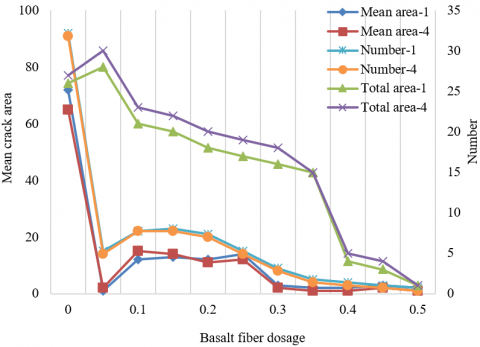
Table 8 reports the area and number of surface cracks on RBGFRCs mixed with different dosages of green fibers after being cured for 1 day and 4 days. Figure 4 shows the influence of green fiber dosage on the area and number of surface cracks of the road bridges made of these RBGFRCs.
Under the green fiber dosage of 0.06%, there were many cracks on the surface of the concrete, but the total crack area per unit area plunged, because the cracks propagate slowly and remain short. When the green fiber dosage increased to 0.12%-0.18% and the fibers became unreasonably distributed, the total crack area started to widen. After the dosage surpassed 0.24%, the crack situation remained stable.
Table 7. Splitting tensile data of RBGFRC
|
Dosage |
4-day compressive strength |
8-day compressive strength |
16-day compressive strength |
30-day compressive strength |
|
0 |
1.75 |
2.72 |
2.76 |
2.81 |
|
0.06 |
2.32 |
2.34 |
2.62 |
2.92 |
|
0.12 |
2.53 |
2.95 |
2.99 |
3.01 |
|
0.18 |
1.92 |
2.57 |
2.79 |
3.09 |
|
0.24 |
1.87 |
2.90 |
2.98 |
3.13 |
|
0.30 |
2.12 |
3.12 |
3.35 |
3.55 |
|
0.36 |
2.38 |
2.78 |
3.19 |
3.47 |
|
0.42 |
2.45 |
2.65 |
2.91 |
3.24 |
Table 8. Early cracking data
|
Dosage |
Day 1 |
Day 4 |
||||
|
Mean crack area |
Number of cracks |
Total crack area |
Mean crack area |
Number of cracks |
Total crack area |
|
|
0 |
61.25 |
16.38 |
1007.79 |
42.52 |
21.47 |
1045.44 |
|
0.06 |
1.32 |
21.08 |
31.93 |
1.78 |
32.75 |
37.98 |
|
0.12 |
13.57 |
10.58 |
147.26 |
14.62 |
10.58 |
148.26 |
|
0.18 |
11.38 |
6.23 |
79.78 |
11.79 |
6.24 |
81.72 |
|
0.24 |
9.2 |
2.07 |
19.98 |
9.75 |
2.02 |
19.37 |
|
0.30 |
1.1 |
8 |
2.3 |
1.0 |
7 |
2.1 |
|
0.36 |
0.9 |
6 |
1.8 |
0.7 |
5 |
1.5 |
|
0.42 |
0.5 |
2 |
1 |
0.2 |
1 |
0.5 |
Figure 4. Influence on the area and number of surface cracks
Through experiments, the RBGFRC durability was analyzed from three aspects: carbonation resistance, resistance to freeze-thaw cycles, and porosity.
Table 9. Carbonation data of RBGFRC
|
Dosage |
Mean 8d carbonation depth |
Mean 30d carbonation depth |
|
0 |
0.75 |
8.03 |
|
0.06 |
0.42 |
6.75 |
|
0.12 |
0.47 |
10.57 |
|
0.18 |
0.62 |
9.25 |
|
0.24 |
0.77 |
9.10 |
|
0.30 |
0.66 |
9.10 |
|
0.36 |
0.65 |
10.68 |
|
0.42 |
0.92 |
10.68 |
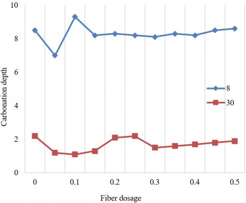
The calcium hydroxide generated through cement hydration reacts with the carbon dioxide in the air, leading to the carbonation of concrete. This directly brings down the alkalinity of road bridge concrete. The ensuing corrosion of internal rebars will further damage the bridge structure.
Table 9 presents the carbonation data of RBGFRCs with different fiber dosages after being cured for 8 days, and 30 days, respectively. Figure 5 shows the influence of green fiber dosage on the carbonation depth strength of the road bridges made of these RBGFRCs.
Figure 5. Influence on carbonation depth
Table 10. Relative dynamic moduli of RBGFRC
|
Dosage |
0 time |
10 times |
20 times |
30 times |
40 times |
50 times |
|
0 |
100.00 |
97.30 |
91.40 |
85.40 |
74.60 |
56.72 |
|
0.06 |
100.00 |
98.60 |
93.90 |
87.50 |
76.30 |
61.21 |
|
0.12 |
100.00 |
98.55 |
92.80 |
88.10 |
78.90 |
66.35 |
|
0.18 |
100.00 |
97.20 |
91.20 |
85.20 |
77.65 |
58.37 |
|
0.24 |
100.00 |
98.60 |
92.30 |
84.90 |
78.80 |
65.34 |
|
0.30 |
100.00 |
98.80 |
94.20 |
91.50 |
84.00 |
68.75 |
|
0.36 |
100.00 |
98.55 |
98.10 |
94.30 |
92.80 |
89.10 |
|
0.42 |
100.00 |
98.10 |
95.30 |
91.50 |
85.90 |
78.20 |
After being cured for 8 and 30 days, the minimum carbonation depths of the concrete both appeared at the fiber dosage of 0.06%. As the dosage changed from 0.18% to 0.42%, the carbonation depth did not fluctuate obviously. Thus, the carbonation resistance of road bridge concrete slightly drops with the increase in green fiber dosage.
The carbonation resistance of the concrete peaks at the dosage of 0.06%, mainly because the internal pores are filled up by the calcium carbonate produced by the carbonation of the randomly distributed fibers, making the concrete more stable under carbonation. However, with the growth of fiber dosage, intercommunicating holes will appear on the weak bonding interface between green fibers and concrete, which increases the carbonation depth.
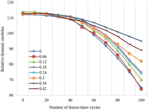
Figure 6. Influence on relative dynamic modulus
Table 10 lists the relative dynamic moduli of concretes enhanced by different dosages of green fibers through 0-50 freeze-thaw cycles. Figure 6 shows the influence of green fiber dosage on the relative dynamic modulus of the road bridges made of these RBGFRCs.
Before the 35th cycle, the RBGFRCs mixed with different dosages of green fibers differed slightly in relative dynamic modulus; After that cycle, the difference gradually increased with the freeze-thaw cycles. It can be proved that RBGFRC has better resistance to freeze-thaw cycles than the original concrete.
The rising resistance to freeze-thaw cycles is attributable to the fact that the bridge structure is densified as the randomly distributed green fibers fill the internal pores of the concrete, which reduces the stress difference created by the alternation between positive and negative temperatures.
Table 11. Mass loss rates
|
Dosage |
0 time |
10 times |
20 times |
30 times |
40 times |
50 times |
|
0 |
0 |
0 |
0.001 |
0.31 |
1.42 |
6.72 |
|
0.06 |
0 |
0 |
0.002 |
0.02 |
0.09 |
0.12 |
|
0.12 |
0 |
0 |
0.002 |
0.01 |
0.08 |
0.25 |
|
0.18 |
0 |
0 |
0.027 |
0.03 |
0.92 |
1.98 |
|
0.24 |
0 |
0 |
0.029 |
0.05 |
0.87 |
0.96 |
|
0.30 |
0 |
0 |
0.003 |
0.06 |
0.08 |
0.25 |
|
0.36 |
0 |
0 |
0.001 |
0.02 |
0.04 |
0.12 |
|
0.42 |
0 |
0 |
0.002 |
0.03 |
0.04 |
0.13 |
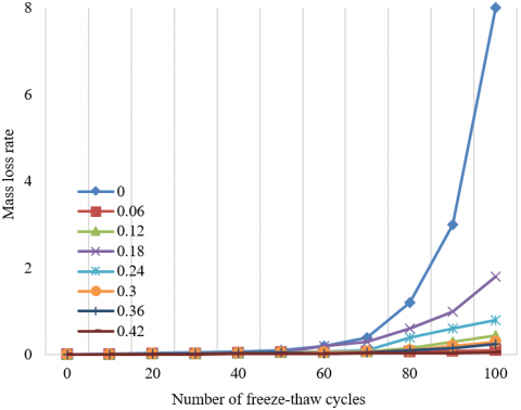
Table 11 lists the mass loss rates of concretes mixed with different dosages of green fibers through 0 to 50 freeze-thaw cycles. Figure 7 shows the influence of green fiber dosage on the mass loss rate of the road bridges made of these RBGFRCs through 0 to 100 cycles.
The mass loss rate of the road bridge did not change much within 50 cycles, and increased at a growing rate after the 50th cycle. The addition of green fibers greatly reduced the mass rate of the concrete. The RBGFRC had much better resistance to freeze-thaw cycles than ordinary concrete.
The superiority mainly comes from the stacking between the randomly distributed green fibers, which enhances the bonding effect of concrete, making the concrete more stable through resistance to freeze-thaw cycles.
Figure 7. Influence on mass loss rate
Table 12. Total porosity of RBGFRC
|
Dosage |
0 |
0.06 |
0.12 |
0.18 |
0.24 |
0.30 |
0.36 |
0.42 |
0.48 |
|
Porosity |
23.55 |
18.67 |
22.98 |
23.72 |
16.34 |
18.29 |
17.65 |
14.11 |
13.98 |
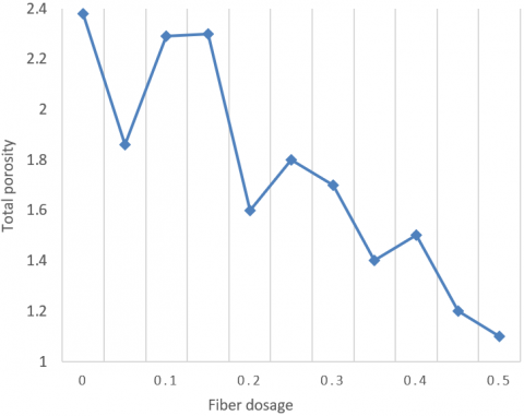
To represent the pore structure of road bridge concrete more intuitively, Table 12 presents the total porosity of concretes mixed with different dosages of green fibers. Figure 8 offers the influence of green fiber dosage on pore distribution of concrete road bridge.
Obviously, the addition of green fibers clearly suppresses the total porosity of concrete. The total porosity minimized at 13.98 at the dosage of 0.48%. The main reason is that green fibers make up the pores, making the concrete denser and more durable.
Figure 8. Influence on total porosity
This paper thoroughly analyzes the physical properties and durability of RBGFRC. Firstly, the authors designed the formulas of crack resistance, shear capacity of oblique section, and bending capacity of normal section. Then, the physical-mechanical properties of RBGFRC were discussed from the angles of flexural strength, compressive strength, splitting tensile strength, and early cracking strength. Experimental results confirm that the mixing of green fibers can, to a certain extent, enhance the resistance of concrete road bridges to compression, bending, tension, and cracking. Next, the authors investigated the durability of the material from carbonation resistance, resistance to freeze-thaw cycles, and porosity. It was learned from experiments that the randomly dispersed green fibers filled up the pores inside the concrete, making the bridge structure denser; that is why the material saw an increase in carbonation resistance, and resistance to freeze-thaw cycles.
[1] Kumar, M., Sinha, A.K., Kujur, J. (2021). Mechanical and durability studies on high-volume fly-ash concrete. Structural Concrete, 22(S1): E1036-E1049. 10.1002/suco.202000020
[2] Zhang, X., Hao, H., Zheng, J., Hernandez, F. (2021). The mechanical performance of concrete shear key for prefabricated structures. Advances in Structural Engineering, 24(2): 291-306. https://doi.org/10.1177/1369433220950618
[3] Tam, V.W., Butera, A., Le, K.N. (2021). Mechanical properties of CO2 concrete utilising practical carbonation variables. Journal of Cleaner Production, 294: 126307. https://doi.org/10.1016/j.jclepro.2021.126307
[4] Pieralisi, R., Cavalaro, S.H.P., Aguado, A. (2021). Discrete element modelling of mechanical behaviour of pervious concrete. Cement and Concrete Composites, 119: 104005. https://doi.org/10.1016/j.cemconcomp.2021.104005
[5] Cuenca, E., D'Ambrosio, L., Lizunov, D., Tretjakov, A., Volobujeva, O., Ferrara, L. (2021). Mechanical properties and self-healing capacity of Ultra High Performance Fibre Reinforced Concrete with alumina nano-fibres: Tailoring Ultra High Durability Concrete for aggressive exposure scenarios. Cement and Concrete Composites, 118: 103956. https://doi.org/10.1016/j.cemconcomp.2021.103956
[6] Hassan, M., Benmokrane, B., ElSafty, A., Fam, A. (2016). Bond durability of basalt-fiber-reinforced-polymer (BFRP) bars embedded in concrete in aggressive environments. Composites Part B: Engineering, 106: 262-272. https://doi.org/10.1016/j.compositesb.2016.09.039
[7] Palm, S., Proske, T., Rezvani, M., Hainer, S., Müller, C., Graubner, C.A. (2016). Cements with a high limestone content–mechanical properties, durability and ecological characteristics of the concrete. Construction and Building Materials, 119: 308-318. https://doi.org/10.1016/j.conbuildmat.2016.05.009
[8] Sato, J., Tokushige, H. (2016). Experimental study on physical characteristics and durability of mortar and concrete using melt-solidified slag fine aggregate. Zairyo/Journal of the Society of Materials Science, 65(1): 91-96. https://doi.org/10.2472/jsms.65.91
[9] Pan, L., Ying, Z.Q., Fan, Z.H., Tian, J.F., Li, Q.W. (2016). Environmental load model and durability analysis of marine concrete structures based on in-situ test data in south China. Engineering Mechanics, 33: 168-172. https://doi.org/10.6052/j.issn.1000-4750.2015.04.S019
[10] Kim, D.G., Lee, D.U., Yang, E.I., Cha, H. (2016). Durability of latex-modified concrete carried by ready-mix truck for concrete rooftops. Magazine of Concrete Research, 68(6): 318-324. https://doi.org/10.1680/jmacr.15.00106
[11] Lezgy-Nazargah, M., Emamian, S.A., Aghasizadeh, E., Khani, M. (2018). Predicting the mechanical properties of ordinary concrete and nano-silica concrete using micromechanical methods. Sādhanā, 43(12): 1-10. https://doi.org/10.1007/s12046-018-0965-0
[12] Yoo, D.Y., Banthia, N. (2016). Mechanical properties of ultra-high-performance fiber-reinforced concrete: A review. Cement and Concrete Composites, 73: 267-280. https://doi.org/10.1016/j.cemconcomp.2016.08.001
[13] Mohammadi, I., Khabbaz, H., Vessalas, K. (2016). Enhancing mechanical performance of rubberised concrete pavements with sodium hydroxide treatment. Materials and Structures, 49(3): 813-827. https://doi.org/10.1617/s11527-015-0540-7
[14] Gamage, J.C.P.H., Al-Mahaidi, R., Wong, M.B. (2016). Integrity of CFRP-concrete bond subjected to long-term cyclic temperature and mechanical stress. Composite Structures, 149: 423-433. https://doi.org/10.1016/j.compstruct.2016.04.040
[15] Wang, L., Jiang, H., Li, Z., Ma, G. (2020). Mechanical behaviors of 3D printed lightweight concrete structure with hollow section. Archives of Civil and Mechanical Engineering, 20(1): 1-17. https://doi.org/10.1007/s43452-020-00017-1
[16] Noushini, A., Hastings, M., Castel, A., Aslani, F. (2018). Mechanical and flexural performance of synthetic fibre reinforced geopolymer concrete. Construction and Building Materials, 186: 454-475. https://doi.org/10.1016/j.conbuildmat.2018.07.110
[17] Ragalwar, K., Heard, W.F., Williams, B.A., Kumar, D., Ranade, R. (2020). On enhancing the mechanical behavior of ultra-high performance concrete through multi-scale fiber reinforcement. Cement and Concrete Composites, 105: 103422. https://doi.org/10.1016/j.cemconcomp.2019.103422
[18] Alzeebaree, R., Çevik, A., Mohammedameen, A., Niş, A., Gülşan, M.E. (2020). Mechanical performance of FRP-confined geopolymer concrete under seawater attack. Advances in Structural Engineering, 23(6): 1055-1073. https://doi.org/10.1177/1369433219886964
[19] Kim, M.J., Kim, S., Yoo, D.Y., Shin, H.O. (2018). Enhancing mechanical properties of asphalt concrete using synthetic fibers. Construction and Building Materials, 178: 233-243. https://doi.org/10.1016/j.conbuildmat.2018.05.070
[20] Smarzewski, P., Barnat-Hunek, D. (2016). Mechanical and durability related properties of high performance concrete made with coal cinder and waste foundry sand. construction and Building Materials, 121: 9-17. https://doi.org/10.1016/j.conbuildmat.2016.05.148
[21] Baz, B., Aouad, G., Leblond, P., Al-Mansouri, O., D'hondt, M., Remond, S. (2020). Mechanical assessment of concrete–Steel bonding in 3D printed elements. Construction and Building Materials, 256, 119457. https://doi.org/10.1016/j.conbuildmat.2020.119457
[22] Bhosale, A., Zade, N.P., Sarkar, P., Davis, R. (2020). Mechanical and physical properties of cellular lightweight concrete block masonry. Construction and Building Materials, 248: 118621. https://doi.org/10.1016/j.conbuildmat.2020.118621
[23] Yildizel, S.A., Calis, G., Tayeh, B.A. (2020). Mechanical and durability properties of ground calcium carbonate-added roller-compacted concrete for pavement. Journal of Materials Research and Technology, 9(6): 13341-13351. https://doi.org/10.1016/j.jmrt.2020.09.070
[24] Devi, S.C., Khan, R.A. (2020). Effect of graphene oxide on mechanical and durability performance of concrete. Journal of Building Engineering, 27: 101007. https://doi.org/10.1016/j.jobe.2019.101007
[25] Li, C.Z. (2020). Mechanical and transport properties of recycled aggregate concrete modified with limestone powder. Composites Part B: Engineering, 197: 108189. https://doi.org/10.1016/j.compositesb.2020.108189
[26] Zhadanovsky, B. (2018). Mechanical processing of concrete and reinforced concrete with diamond tool. In MATEC Web of Conferences, 193: 03013. https://doi.org/10.1051/matecconf/201819303013
[27] Bui, N.K., Satomi, T., Takahashi, H. (2018). Mechanical properties of concrete containing 100% treated coarse recycled concrete aggregate. Construction and Building Materials, 163: 496-507. https://doi.org/10.1016/j.conbuildmat.2017.12.131
[28] De Brito, J., Ferreira, J., Pacheco, J., Soares, D., Guerreiro, M. (2016). Structural, material, mechanical and durability properties and behaviour of recycled aggregates concrete. Journal of Building Engineering, 6: 1-16. https://doi.org/10.1016/j.jobe.2016.02.003