Feifei Zhao
© 2021 IIETA. This article is published by IIETA and is licensed under the CC BY 4.0 license (http://creativecommons.org/licenses/by/4.0/).
OPEN ACCESS
In this paper, finite-element analysis (FEA) is carried out on the temperature field and stress field of automobile engine piston, as well as the thermal-mechanical load coupling stress field. Through the analysis, the authors grasped the thermal load and combined stress distribution of the piston, and thus optimized the piston design to improve its operational reliability. Specifically, a 1/4 solid model of the piston was constructed in the three-dimensional (3D) computer-aided design (CAD) software Pro/ENGINEER, and then converted into a finite-element model in Pro/Mechanica. Then, an alternating load was imposed on the piston model, and fatigue analysis was performed to identify the parts of the piston prone to fatigue failure, and judge whether the piston structure satisfies working requirements. Next, temperature field analysis was carried out on the piston model. The distribution of the steady-state temperature field as determined by applying temperatures and heat transfer coefficients as required by the boundary conditions of the third kind. Finally, the piston model was subject to thermal-mechanical coupling analysis. The stress and deformation distributions of the piston under the coupled stress field were ascertained under the boundary conditions of temperature field distribution and mechanical load. Through the above work, the authors obtained the basis for safety evaluation of piston, laying the foundation for further reducing the thermal load and optimizing the stress distribution of piston.
diesel engine piston, aluminum-based material, finite-element analysis (FEA), stress distribution, temperature distribution
In response to the increasingly strict standards on engine emissions, many new technologies have been developed and rapidly applied in the market [1, 2], such as variable valve timing & lift electronic control (VTEC), and offset crankshaft technology. Thanks to these technologies, engine performance can be improved in various aspects, ranging from power increase, fuel saving, to emission control. However, the new technologies pose higher requirements on the overall strength and load capacity of the engine [3, 4], bringing new forms of cracks, wear, and corrosion to the key components.
One of the key components of internal combustion engine is piston. This component has a complex structure and operates under a complicated environment. During the operation, the fast reciprocating motion generates cyclic loads like inertia force, lateral thrust, and frictional force. These cyclic loads, coupled with the stress from high-pressure fuel gas, cause mechanical stress and deformation to the piston. Under the harsh working conditions, the quality of the piston directly bears on the service life of the engine.
Specifically, the combustion of high-pressure gas produces a high temperature, heating up the top and even the entirely of the piston, but in an unevenly manner [5]. The ensuing thermal stress and deformation will increase the thermal expansion of the piston, and damage the normal gap between the piston and cylinder wall [6, 7]. The thermal load and mechanical load jointly act to induce piston cracking, gum up piston ring, and scuff cylinder bore. Due to the cyclic thermal-mechanical stress, the material inside the piston will suffer from fatigue damage [7-9], which could damage or destroy the piston and the entire engine.
To improve the operational reliability of piston, it is important to understand the combined stress distribution of the piston by analyzing the temperature field, stress field, as well as the coupled stress field under both thermal and mechanical loads of the piston in the early design phase. FEA has become the top choice for many engine researchers to study and solve the structural fatigue and thermal-mechanical coupling of pistons.
Currently, finite-element method is the most widely used numerical method in engineering analysis. In addition to structural analysis in engineering, this approach can effectively solve problems in heat transfer, fluid mechanics, electromagnetics, and acoustics. The results of FEA provide a reliable basis for the design and performance analysis of various industrial products. If finite-element method is applied to analyze the piston model, the structural strength and thermal load of the piston components can be directly parsed, and the analysis results can be used to verify the effectiveness of experiments.
In recent years, the coupled model analysis of piston, piston rings, cylinder liner, and piston pin comes true, owing to the constantly improving functions of FEA software and the rapid progress in computer hardware. The coupled model analysis of piston group has become a hot topic among foreign scholars of internal combustion engines. Many of them explored the heat transfer of internal combustion engines like piston groups by coupling FEA with computational fluid dynamics (CFD). The CFD could be adopted to calculate the temperature and heat transfer coefficient of the working medium atop the piston, as well as the coupled model of cylinder liner. But this approach has not been widely applied. Feng Liqi et al. performed an FEA on a 6E160 diesel engine piston group, constructed a 1/4 solid model of the piston group, and meshed it into 32,593 tetrahedron elements and 14,941 nodes, followed by a thorough analysis on the three-dimensional (3D) models of the piston group and cylinder liner. Bai Minli et al. also simulated the heat transfer of the piston group-cylinder liner coupling model, established a 3D coupled model based on the relevant physical fields and the combined heat transfer relationship between components, and obtained results similar to experimental data.
The heat transfer of the piston is a complex process, making it difficult to determine the thermal boundary conditions of piston. In general, these conditions are either treated as boundary conditions of the first kind derived from the known boundary temperature of the piston, or boundary conditions of the third kind derived from the known heat transfer coefficient between piston and other media. For the inconvenience of measuring the temperature at every surface node of the piston, the boundary conditions of the third kind are usually adopted for engineering calculation. However, it is no easy task to determine the heat transfer coefficient and ambient temperature for the boundary conditions of the third kind. In reality, these parameters are often obtained by trial-and-error: First, empirical formulas are selected to estimate the heat transfer coefficients between piston boundary and fuel gas, cylinder liner, engine oil in cooling chamber, and oil mist in crankcase, and the temperatures of the relevant media; Then, the temperature field of the piston was calculated; After that, the calculated temperatures of some feature points are verified against the previously measured temperatures, and correctly repeatedly until the two temperatures are basically the same.
Concerning the heat transfer of modern internal combustion engines, an important research direction is to couple the models of the gas flow, combustion, heat convection, and heat radiation in the cylinder with the components of the combustion chamber, and perform full-scale simulation of the model [10, 11]. At present, foreign scholars mostly couple CFD with FEA to examine the heat transfer of piston and other components of internal combustion engines: the temperatures and heat transfer coefficients of the piston top and cylinder liner cooling water are calculated, from which to derive the boundary conditions of the third kind.
Non-steady state analysis and transient analysis also mark the future trend of the numerical simulation of the piston in internal combustion engines. For example, Panayi et al. [12] successfully carried out the transient analysis of the coupling model for the piston group, through the use of parametric language and the control of time-variation of finite-element grids. Moreover, some foreign scholars [13] have investigated the influence of carbon deposit in cylinder, thickness of lubricating oil form, and intake vortex strength on heat transfer.
The thermal load resistance and thermal strength of piston are crucial to improving the technical level of the whole machine, directly affecting the operational reliability and durability of the engine. As modern engines evolve towards high pressure and high strength, it is far from enough to consider mechanical load only for heated parts like piston. During engine operation, heat cracking and scarification are commonplace, as local thermal load is so high as to surpass the ultimate thermal strength of the material. Therefore, it is a research hotspot to calculate the heat transfer and thermal load in the cylinder of the internal combustion engines, and optimize the cylinder structure through computer-aided design (CAD).
The thermal load is usually determined according to the following parameters: the highest working temperature of parts, the local temperature gradients of different directions and the corresponding thermal loads and thermal stresses, as well as the low- and high-frequency thermal fatigues of local parts. With the aid of computer technology, this paper establishes the geometric model of an engine piston in Pro/ENGINEER, aiming to solve the part damage by the excessive temperature of heated parts in engineering. The research also attempts to shed new lights on the application of numerical simulation in the early design of future engines, avoiding aimless design and reducing experimental cost.
The specific contents of the work are as follows: First, a 1/4 solid model of the piston was created on the 3D CAD software Pro/ENGINEER, and imported to the Pro/Mechanica structure analysis module. An abundance of data was obtained through data analysis and processing. Then, the motion and force state of the piston in the cylinder were analyzed, and the factors affecting the piston strength and deformation were identified, creating a theoretical method to simplify the model. Under proper boundary conditions and constraints, the deformation and stress of the piston were computed under gas pressure and other loads. After that, the coupled field analysis module of Pro/Mechanica was employed to calculate the temperature field of the piston through steady-state thermal analysis, and derive the distribution of heat flow in the piston and the thermal gradient in each part of the piston. Moreover, thermal stress and thermal fatigue were deliberated, completing the thermal load analysis of the piston. Finally, both mechanical and thermal loads were applied to the piston, and the strength and deformation of the piston were discussed under the joint action of the two loads.
2.1 Design requirements
The piston functions to withstand gas pressure and drive the crankshaft rotation via the piston pin, and the top of the piston is an integral part of the combustion chamber. The thermal load of the piston is a constraint on the further enhancement of internal combustion engines. Therefore, an important consideration in piston design is to consider the factors affecting the thermal load, and to quantify and reduce thermal load [12]. The piston design must pay attention to the following issues:
(1) Select frictional-resistant and manufacturable materials that have sufficient mechanical strength, wear resistance, small specific gravity, small thermal expansion coefficient, good thermal conductivity, under 300-400°C. The selection of suitable piston materials helps to extend the service life of the piston, reduce fuel consumption, dampen noise, control emissions, and protect the environment [14, 15].
(2) Design reasonable shape and wall thickness, minimize piston weight, and alleviate stress concentration, so that the heat dissipation is good, and the strength and stiffness are as required. Take measures to control the expansion of the skirt section, and adopt piston cooling measures if necessary.
(3) Without increasing the friction loss of the piston group, ensure the airtightness of the combustion chamber, control the amount of pumped oil within preset limit, and provide enough lubricating oil on the sliding surface.
(4) Design a reasonable skirt section and a rational cylinder gap, so that the piston and cylinder can work out the best fit under any working condition, and reduce the probability of cavitation induced by cylinder knocking and cylinder liner vibration.
2.2 Modeling of piston
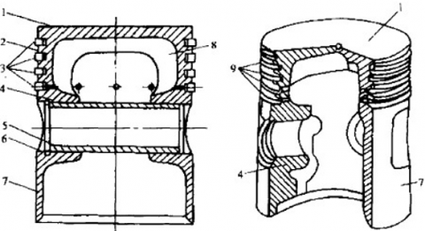
The structure of the piston can be divided into three parts: the top, the head (ring slot), and the piston (Figure 1).
1. Top; 2. Head; 3. Ring; 4. Pin boss; 5. Pin; 6. Snap ring; 7. Skirt; 8. Reinforced rib; 9. Ring slot
Figure 1. Piston profile
For simplicity, the following assumptions were made before analyzing piston structure:
(1) Do not consider the cylinder when modeling.
(2) Do not consider the piston ring during solid modeling, but draw the ring slot on the piston model. This is to simplify the modeling and analysis. After all, the alternating mechanical stress mainly affects the pin boss of the piston structure.
(3) Do not consider the oil hole when modeling. If the oil hole is contained in the solid model, the FEA will be too complex to achieve the desired accuracy.
(4) Consider the piston top of diesel engine as a smooth surface with various pits. This helps to improve the formation and combustion of mixed gas, and adjust the compression ratio of the engine.
(5) Consider the skirt as a variable ellipsis with its minor axis pointing to the pin boss direction. This prevents cylinder scuffing and sticking caused by the large expansive deformation of the piston in the pin boss direction.
(6) Do not consider the change in force and displacement of piston pin induced by the planar motion of the rod; replace the effect of the rod with a constraint; treat the piston as a symmetrical entity to reduce the computing load.
Next, this paper establishes a model of the piston according to the above structural analysis and assumptions. The top and head were modeled by the rotation tool.
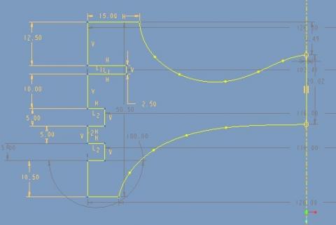
The piston top of the diesel engine often has various pits. This paper adopts a W-type combustion chamber; the piston head is generally thick, the profile from the top to the ring slot is made as smooth as possible, with a sufficiently large transition corner R (Figure 2).
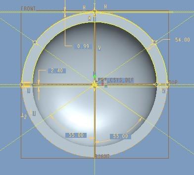
The skirt and pin boss were established with a mirror tool. During the operation, the mechanical and thermal deformations turn the skirt profile of the piston into an ellipse with its major axis pointing in the pin boss direction. To keep the shape of the operating piston close to a cylinder and maintain a small and uniform gap, the skirt section was made into a variable ellipsis, with the major axis equal to the piston diameter of 126mm and the minor axis at 124mm in the direction of the pin boss (Figure 3).
Figure 2. Head profile
Figure 3. Skirt section
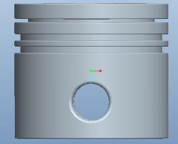
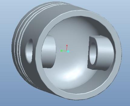
Figures 4 presents our piston model. The model is 126cm in diameter, and 110cm in height; the pin hole is 30cm in diameter.
|
(a) Front view |
(b) Side view |
Figure 4. 3D model of the piston
During the operation, the piston needs to withstand a huge load induced by the burst pressure of gas and the reciprocating inertia force. In this section, the load of the operating piston is examined in Pro/Mechanica for structure and fatigue analysis, with the aim to identify the maximum mechanical stress and fatigue failure positions of the piston.
3.1 Stress analysis
The first step of structural analysis on the piston is to determine the various forces acting on it, including the fuel gas pressure on piston top produced by the gas pressure in the combustion chamber; the normal pressure on the primary and secondary thrust sides of the piston produced by the contact of the moving fluid and the small bulges on piston surface, and its torque on the centerline of piston pin; the frictional forces on the primary and secondary thrust sides of the piston produced by the contact of the moving fluid and the small bulges on piston surface, and its torque on the centerline of piston pin; the inertia forces of the piston and the pin produced by the reciprocating motions of the piston; the inertia force of the piston, inertial torque, and the inertia force of the pin produced by second-order motions of the piston; the force on the piston produced by the rod, which always points to the length direction of the rod.
Among the multiple forces and torques acting on the piston, only four forces actually cause the piston to deform: gas pressure in the combustion chamber FG, alternating inertia force of the piston FIC, normal force F, and the force on the pin boss produced by the rod $\bar{F}$. The stress diagram of the piston is shown in Figure 5.
Figure 5. Stress diagram of the piston
During the operation, the piston bears the highest pressure, faces the greatest stress, and suffers from the most severe deformation, at the moment when the burst pressure in the cylinder reaches the peak point. Therefore, it is of great significance to analyze the piston strength at that moment. For each diesel engine piston, its top could be hit by a high pressure as high as 6-9MPa brought by the fuel gas, during the working stoke. Meanwhile, the normal pressure was not considered, for its limited impact.
To measure the integrated effect of the burst pressure of fuel gas and the inertia force of the piston, the combined force of the two stresses was applied on the piston surface as a load. In this way, it is much easier to apply load on the piston, while counting the impacts of both stresses. Hence, a pressure Pmax=9MPa was imposed on the top surface and the land of the piston. From the angle of mechanical load, the stress state of the piston was examined through stress and strain analysis, and the vulnerable points of the piston under stress were identified, providing a reference for design optimization.
3.2 Stress analysis
3.2.1 Material parameters of piston
At present, domestic pistons are mostly made of aluminum alloy, cast iron, and cast steel. Compared to the traditional cast iron/ cast steel pistons, aluminum alloy piston enjoys a number of advantages [16]: light weight, good wear resistance, and small dynamic load. Aluminum alloy has much better thermal fatigue resistance and high-temperature strength than matrix alloy. These advantages, together with its low linear expansion coefficient, contribute to the popularity of aluminum alloy pistons in medium-to-high-speed internal combustion engines with small and medium cylinders, especially in car engines [17].
With aluminum as the matrix, aluminum-based composite has relatively good plasticity and toughness. The addition of the wild phase substantially enhances the resistance of the material to tension, compression, wear, pressure, and corrosion [18]. Under the same working condition, aluminum alloy pistons produce a much smaller inertia force than steel pistons with the same strength properties. The aluminum alloy can improve the vibration damping of high-speed internal combustion engines, and reduce their specific mass. The lightweight aluminum alloy piston generates small side pressures and impacts to the cylinder walls. As a result, the frictional force between piston group, piston pin, and cylinder walls will plunge, causing a decline to the wear of these components.
The most widely used aluminum alloy is the Al-Si series, which encompasses four sub-series: Al-Cu-Si, Al-Cu-Ni-Mg, eutectic Al-Si-Cu-Mg, and hypereutectic A1-Si-Cu-Mg. Among them, the first two series have been phased out, due to their large expansion coefficients and specific gravities. Nowadays, domestic pistons mainly adopt eutectic Al-Si alloys, namely, ZL108, and ZL109. ZL108 boasts excellent casting properties and airtightness. ZL109 features good high-temperature performance, owing to the adjustment of the ratios of Al, Si, Cu, and Mg and the addition of Ni. ZL109 is usually prepared into complex castings, such as motor housings, cylinder blocks, and engine pistons.
The only weakness of aluminum alloy pistons lies in the poor high-temperature performance, which easily leads to ablation. This weakness can be solved by modifying the surface through micro-arc oxidation [19]. The surface modification can improve the surface properties of the aluminum alloy pistons, extending their service life. Currently, the advanced casting techniques of aluminum alloy pistons are possessed by developed countries like the United States, Japan, and South Korea. China has the ability to independently develop and manufacture aluminum alloy pistons for engines, but the domestically made products are not as good as foreign products in casting process and quality [20].
In this paper, the piston is made of ZL109G eutectic Al-Si alloy, whose Poisson’s ratio μ is 0.3, elastic modulus E is 71GPa, density ρ is 2.7×10³kg/m3, thermal expansion coefficient α is 2.3×10⁻⁵/°C, and tensile yield/limit stress is 325/493MPa. In Pro/Mechanica, a new eutectic Al-Si alloy was created, the properties of the material were defined, and the material was assigned to the piston.
3.2.2 Stress distribution
The compressive load manifests as the high pressure acting on piston top, which comes from the pressure of the working gas in the cylinder. For simplicity, the compressive loading can be treated a steady-state process. However, the impact load from the combustion working stroke to the piston cannot be neglected. To ensure the reliability of piston life evaluation, the mean pressure on piston top was set to a value higher than the actual level, approximating the peak pressure in a cycle.
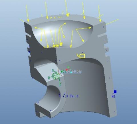
Figure 6. Definitions of constraints and loads
Figure 7. Static stress distribution of the piston
As shown in Figure 6, a 9MPa load was applied on the top surface and land of the piston according to the working condition. After setting up the simulation model, a new static analysis was initiated. Once the analysis command was executed, Pro/ENGINEER automatically meshed the piston into grids, and calculated the stress distribution of the piston under load (Figure 7).
Under the mechanical load, the maximum mechanical stress of the piston (250MPa) appeared on the contact between piston pin and pin boss, while the stress on the combustion chamber atop the piston was below 100MPa. Both stress values were smaller than the tensile yield stress of the material, which agrees with the statement on the design manual of the diesel engine. In fact, this contact surface is the part of the pin boss most vulnerable to cracking. The reason for the stress to concentrate locally on the inner edge of the upper surface of the pin boss is as follows: the piston bends as it moves up and down near the top dead center (TDC), causing deformation to the pin boss; but the deformation is hindered by the relatively stiff upper surface of the pin boss.
3.3 Fatigue analysis
The high-temperature fatigue failure roughly takes up 46% of all piston failures. The large proportion highlights the necessity of fatigue analysis [21, 22]. Here, the expected limit of piston’s fatigue life is set to 1×10⁸, i.e., the engine piston is expected to stay immune to fatigue failure in 10 billion cycles. After systematic calculation, the fatigue life of the piston was found to be 1×10²⁰, far greater than the preset value of 1×10⁸. Therefore, the running result has a higher confidence than the expected value.
Figure 8. Fatigue life distribution of the piston
Figure 9. Fatigue life confidence distribution of the piston
By analyzing the records and confidence of fatigue life, this paper obtains the fatigue life distribution (Figure 8) and fatigue life confidence distribution (Figure 9) of the piston. As shown in Figure 8, the fatigue life in any position of the piston was greater than the expected value of 1×10⁸, indicating that the piston structure can fully meet the work requirements. As shown in Figure 9, the structure most likely to suffer from fatigue failure is the edge close to the small end of the rod and on the upper surface of the piston structure. The results of fatigue analysis provide a reference for improving piston structure.
4.1 Thermal analysis
4.1.1 Boundary conditions of temperature field
The temperature field of the piston is usually calculated under the boundary conditions of the third kind, i.e., the boundary conditions for heat convection. To configure such conditions, the main task is to determine the heat transfer coefficients α between each boundary and fuel gas, cooling water, cooling oil, and oil mist in crankcase, as well as the temperatures T0 of the relevant media.
However, there are sharp differences in working conditions between the top, sides, and cavity of the piston. It is not easy to determine the boundary conditions for heat convection. The key difficulty lies in findings a general formula that accurately calculates the heat transfer coefficient between the piston and the surrounding medium. In many cases, the heat transfer coefficients are determined by empirical or semi-empirical formulas [21, 22]. Quite a number of researchers simplified the temperature field of the piston as an axially symmetric temperature field. In this paper, the temperature field of the piston is regarded as a 3D temperature field, in view of the non-axial symmetry of engine structure, and the heat transfer conditions between each boundary of the piston and the surrounding medium (e.g., fuel gas, cooling water, and cooling oil).
By comparing the boundary conditions of similar models and referring to the existing research results, our research data fully reflect the parameter differences of similar models, and highlight their similarities. Through repeated calculations and corrections, the composite boundary conditions of each surface of the piston were determined as shown in Table 1.
Table 1. Boundary conditions of each surface of the piston
|
Corresponding area |
Heat transfer coefficient (W/(m2·K)) |
Ambient temperature (°C) |
|
|
Combustion chamber |
425 |
667 |
|
|
Top surface |
415 |
663 |
|
|
Piston land |
260 |
207 |
|
|
First ring |
Upper edge |
600 |
197 |
|
Middle edge |
500 |
||
|
Lower edge |
500 |
||
|
Ring between first and second rings |
500 |
192 |
|
|
Second ring |
Upper and lower edges |
650 |
187 |
|
Middle edge |
500 |
||
|
Ring between second and third rings |
500 |
170 |
|
|
Third ring |
Upper and lower edges |
750 |
152 |
|
Middle edge |
600 |
||
|
Skirt |
300 |
90 |
|
|
Cavity |
Upper edge |
800 |
87 |
|
Middle edge |
630 |
||
|
Lower edge |
350 |
||
|
Pin hole |
220 |
122 |
|
4.1.2 Distribution of temperature field
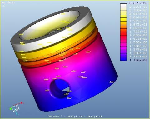
The above model was converted into the Pro/Mechanica simulation environment. After selecting the analysis mode, and loading the thermal boundary conditions, the authors analyzed the steady-state thermal analysis on the piston, and calculated the temperature field. Figures 10 and 11 depict the distribution of temperature field of the piston.
Figure 10. Temperature field distribution on outer surface of the piston
The following can be observed from the temperature field distribution in Figure 10:
Under the cyclically changing fuel gas temperature, the steady-state temperature of the piston was about 229.9°C. The maximum temperature appeared at the center of piston top. There was also a large difference in temperature distribution within the combustion chamber: the bottom ring of the chamber was relatively cold, with the lowest temperature of 208°C; the central bulge of the chamber was relatively hot, with the peak temperature of 229°C. In the skirt section, the temperature in the pin hole direction was higher than that in the other direction; the lowest temperature at the lower end of the skirt was about 120°C; the temperature of the pin boss was between 130°C and 160°C; that is why the piston was deformed relatively significantly in the direction of the pin.
In piston land, the temperature fell between 215°C and 229°C. The temperature of piston rings is critical to the engine reliability. The first ring had a temperature of 200-227°C, which is not so high as to damage the airtightness of the ring; otherwise, the lubricating oil will have gum and carbon deposits, affecting the operating reliability of the engine. Besides, the surface temperature at piston rings dropped obviously at the first ring, and decreased evenly by 14°C between adjacent rings from the first ring downward.
The temperature field distribution inside the piston can be observed from Figure 11.
The temperature was relatively high at the contact between the side walls of the pitted combustion chamber and the top surface of the piston, which stood at 227°C; the highest temperature of 229°C appeared at the roof center of the chamber, higher than the surface temperature of the bottom (208°C). From top to the bottom, the surface temperature gradually decreased on the side walls of the chamber. The temperature peaked at the corner between the upper part of side walls and the top surface of the piston (227°C), decreased to 215°C in the middle part of side walls, and further dropped to 208°C at the corner between the lower part of the walls and the bottom of the chamber.
Figure 11. Temperature field distribution inside the piston
4.2 Thermal-mechanical coupling analysis
In the cylinder, the piston is not only subject to various forces (e.g., burst pressure of cylinder gas, as well as the inertia force, side thrust, and frictional force produced by its rapid alternating motions), and also affected by the cyclic heat release of high-temperature fuel gas. In other words, the piston is under the joint action of thermal load and mechanical load. It is of great necessity to analyze the stress and strain distributions of the piston under the coupling of the two loads. The coupling model simulation can approximate the actual working conditions of the piston. After analyzing the temperature field of the piston, this section relies on indirect coupling method to load the temperature field and mechanical load of the piston simultaneously onto the model, and examines the thermal-mechanical load coupled stress and strain of piston group.
4.2.1 Overview of coupled field analysis
Coupled field analysis means the interaction between two or more engineering disciplines is considered in FEA. If an object is subject to two different working conditions, it would be necessary to perform coupled field analysis. In general, coupled field analysis can be performed directly or indirectly.
Direct coupling method only performs one analysis on the coupled field elements of multiple degrees of freedom; the different fields are coupled together by computing the unit matrix or load vector containing the required physical quantities. Indirect coupling method typically performs two or more analyses in sequence, each of which targets a physical field. Normally, the coupled analysis is completed by loading the results of the current analysis to the subsequent analysis.
Indirect coupling method is more effective and flexible than direct coupling method, when the interaction between multiple physical fields is not highly nonlinear, because each analysis is performed independently. By contrast, direct coupling method is preferable, when multiple physical fields have strongly nonlinear relationships. For nonlinear problems, either unit matrix or load vector strategies needs iterations. If direct coupling method is adopted, the interaction between the coupled fields can be directly solved with some special coupling elements.
In this paper, the piston needs to withstand the impacts of two physical fields: thermal load and mechanical load. During the FEA, the structural models of the piston group contact each other, turning the analysis into a highly nonlinear problem. Therefore, the direct coupling method, which better fits nonlinear problems, was adopted to perform thermal-mechanical coupling analysis, using the boundary conditions for the above thermal and mechanical analyses.
4.2.2 Loads and constraints
Thermal load: The results of steady-state thermal analysis were imposed as thermal load.
Mechanical load: The force produced by the gas in cylinder was simulated by applying pressures on the top and land of piston; the force from the pin to the piston was simulated by applying support reaction to the pin boss. The values of mechanical load were the same as those for mechanical stress simulation.
Constraints: The constraints for structural analysis were directly applied in the coupled field analysis. Taking the pin axis as the Y direction, a global column coordinate system was established, whose origin coincides with that of the local coordinate system of the pin. Then, a constrained surface, which coincides with the upper surface of pin boss, was created, and the radial direction of the column coordinate system was taken as the constrained displacement direction. After that, two symmetry plane constraints were created, and applied on the symmetry planes in the directions of X and Y, respectively, such that the normal displacement of the two symmetry planes are zero.
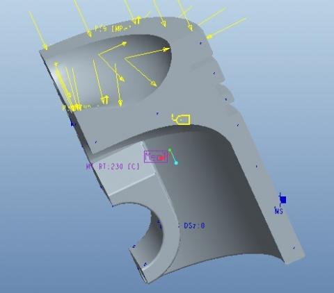
In Pro/Mechanica, the thermal boundary conditions of the piston were established under the thermal analysis environment; after steady-state thermal analysis, the boundary conditions of the forces and constraints on the piston were loaded under the structural analysis environment; MECTEM mode was adopted to load the steady-state thermal analysis into stress analysis in the form of mechanical load, under the same environment, creating a static stress analysis (where structural analysis contains thermal analysis). The resulting heat-structure coupling simulation model is shown in Figure 12.
Figure 12. Heat-structure coupling simulation mode
4.2.3 Stress distribution under thermal-mechanical coupling
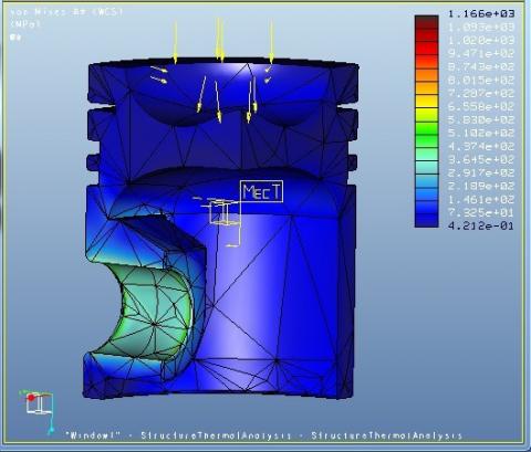
After the execution of the running command, the system automatically meshed the model to obtain the thermal-mechanical coupling stress diagram of the piston (Figures 13 and 14).
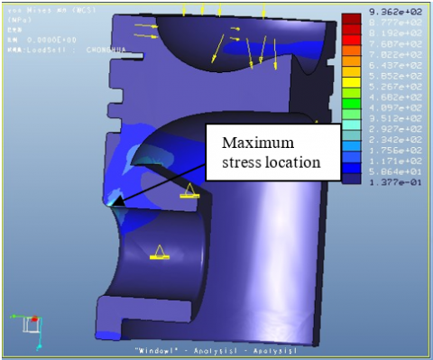
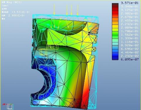
As shown in Figure 13, under the coupling of temperature field and the mechanical load, the peak stress (300MPa) appeared near the inside of the supper surface on the pin hole, while the stress was relatively small in the combustion chamber. The stress of the piston clearly concentrated on the inner edge of the pin, which is the main damage part of the piston, and the focus of optimization design. The junction between the reinforced rib and the top surface is the most vulnerable part of the piston. The combined stress at the top center of the cavity was relatively small (<50MPa), because this part is only under thermal stress, but not greatly affected by mechanical load.
Figure 13. Thermal-mechanical coupling stress diagram 1
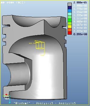
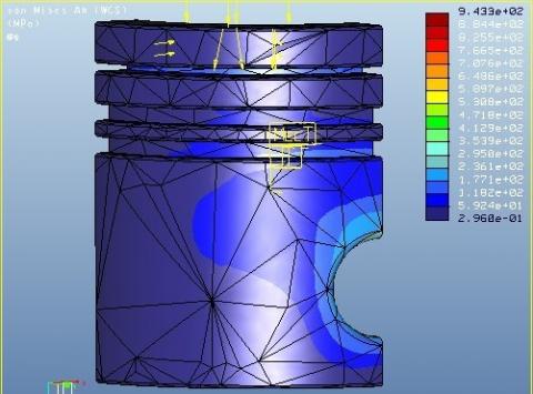
Figure 14. Thermal-mechanical coupling stress diagram 2
As shown in Figure 14, the segment from the upper part of pin boss to piston top had an obviously larger combined stress than the nearby parts, under the forces from high-temperature fuel gas and piston pin. Mainly affected by thermal load, the combined stress on piston ring was relatively small (90MPa). The combined stress on the third ring was relatively large (60MPa), under the combined effect of thermal stress and support reaction. Similarly, relatively large combined stress (260MPa) was observed on the outside of the upper part of the pin boss, due to the large thermal stress and high support reaction.
4.3.4 Deformation distribution under thermal-mechanical coupling
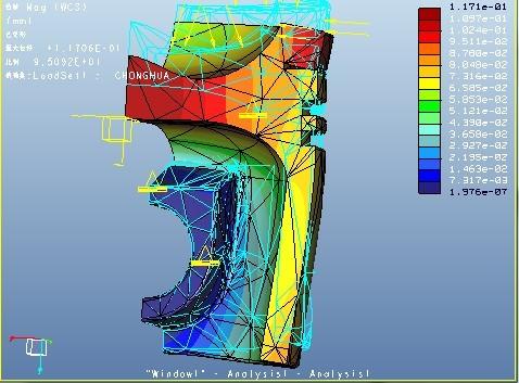
Comparing the deformation distribution under thermal-mechanical coupling (Figure 15) with deformation distribution under mechanical load (Figure 16), it can be seen that: the maximum displacement (0.36mm) of the piston under thermal-mechanical coupling mainly concentrated on the skirt section, pointing to the radial direction of the piston. This displacement was larger than that under pure mechanical load, indicating that the skirt deformation is not only the result of mechanical load, but also the result of thermal load. However, the deformation in this section mainly comes from the mechanical load. The top edge of the piston also had relatively large displacement (0.29mm). Under the combined effect of mechanical and thermal loads, the combined displacement of the piston mainly concentrated on the top edge and skirt bottom. Through overall consideration, the gap between piston and cylinder walls could allow this expansive displacement.
Figure 15. Deformation distribution under thermal-mechanical coupling
Figure 16. Deformation distribution under mechanical load
Under the coupled field, the piston mainly deformed at the head. This result echoes with the effect of thermal load. Therefore, the piston deformation under thermal-mechanical coupling is mainly attributable to thermal load. This conclusion provides a good reference for optimizing piston design.
(1) This paper establishes a 3D model of the piston in Pro/ENGINEER, and performs an FEA on the structure, fatigue, temperature field, and thermal-mechanical coupling of the piston in Pro/Mechanica module, revealing the stress, fatigue, temperature, and deformation distributions of the piston under working conditions.
(2) Structural analysis indicates that the piston is particularly vulnerable on the inner edge of the upper surface of the pin boss, under the combined effect of the burst pressure of fuel gas, alternating inertia force, and support reaction at the pin boss. The maximum equivalent stress stood at 250MPa, lower than the tensile yield stress of piston material (325MPa).
(3) Fatigue life analysis shows that the most vulnerable position of the piston, i.e., the part with the shortest fatigue life, appeared on the upper surface of pin boss and near the small end of the rod, when the expected limit of piston’s fatigue life was set to 1×10⁸.
(4) Thermal analysis suggests that, under the thermal load, the piston saw the temperature peaking at 229°C on the top surface, and minimizing at the lower end of the skirt (120°C). In the skirt section, the direction along the pin hole had a higher temperature and larger deformation than the other direction. The first ring witnessed a relatively high temperature (200-277°C), lower than the gumming temperature (230°C) of the high-temperature lubricating oil for the piston. The heat loss of the piston mainly occurred at the ring.
(5) Thermal-mechanical coupling analysis discovers that, under the joint action of burst pressure of fuel gas and thermal load, the maximum equivalent stress appeared at the pin-pin boss interface (300MPa), about 50MPa greater than that 250MPa under pure mechanical load. Thus, the stress on the piston mainly comes from mechanical load. In addition, the stress trend of the piston under coupled load was the same as that under pure mechanical load, and the equivalent stress under coupled load was larger than that under pure mechanical load. The top edge and skirt were the most severely deformed parts on the piston. The deformation of the top edge is attributable to thermal expansion of the piston, while the deformation of the skirt is the result of mechanical load.
From the above analyses and exploration, some interesting topics are revealed for future research: The heat transfer in internal combustion engines is an extremely complex process, involving both physical and chemical interactions. Therefore, it is very difficult to determine the heat transfer coefficients between the piston and various media. This calls for novel calculation methods that can accurately simulate the temperature field and thermal stress of the piston. Moreover, the contact at piston ring remains a difficulty in the coupled model for piston group. Solving this difficulty could greatly facilitate the determination of boundary conditions.
[1] Venkatachalam, G., Kumaravel, A. (2019). Experimental Investigations on the Failure of Diesel Engine Piston. Materials Today: Proceedings, 16: 1196-1203. https://doi.org/10.1016/j.matpr.2019.05.214
[2] Mohan, B., Yang, W., Raman, V., Sivasankaralingam, V., Chou, S.K. (2014). Optimization of biodiesel fueled engine to meet emission standards through varying nozzle opening pressure and static injection timing. Applied Energy, 130: 450-457. https://doi.org/10.1016/j.apenergy.2014.02.033
[3] Zhang, Q., Li, M., Li, G., Shao, S., Li, P. (2017). Transient emission characteristics of a heavy-duty natural gas engine at stoichiometric operation with EGR and TWC. Energy, 132: 225-237. https://doi.org/10.1016/j.energy.2017.05.039
[4] Cho, C.P., Pyo, Y.D., Jang, J.Y., Kim, G.C., Shin, Y.J. (2017). NOx reduction and N2O emissions in a diesel engine exhaust using Fe-zeolite and vanadium based SCR catalysts. Applied Thermal Engineering, 110: 18-24. https://doi.org/10.1016/j.applthermaleng.2016.08.118
[5] Banerji, A., Lukitsch, M.J., Alpas, A.T. (2016). Friction reduction mechanisms in cast iron sliding against DLC: Effect of biofuel (E85) diluted engine oil. Wear, 368: 196-209. https://doi.org/10.1016/j.wear.2016.09.001
[6] Googarchin, H.S., Sharifi, S.M.H., Forouzesh, F., Hosseinpour, G.H.R., Etesami, S.M., Zade, S.M. (2017). Comparative study on the fatigue criteria for the prediction of failure in engine structure. Engineering Failure Analysis, 79: 714-725. https://doi.org/10.1016/j.engfailanal.2017.05.016
[7] Zhao, B., Dai, X.D., Zhang, Z.N., Xie, Y.B. (2016). A new numerical method for piston dynamics and lubrication analysis. Tribology International, 94: 395-408. https://doi.org/10.1016/j.triboint.2015.09.037
[8] Lu, Y., Zhang, X., Xiang, P., Dong, D. (2017). Analysis of thermal temperature fields and thermal stress under steady temperature field of diesel engine piston. Applied Thermal Engineering, 113: 796-812. https://doi.org/10.1016/j.applthermaleng.2016.11.070
[9] Moosavian, A., Najafi, G., Ghobadian, B., Mirsalim, M., Jafari, S.M., Sharghi, P. (2016). Piston scuffing fault and its identification in an IC engine by vibration analysis. Applied Acoustics, 102: 40-48. https://doi.org/10.1016/j.apacoust.2015.09.002
[10] Liu, J.L. (2018). Application of Analyzing Finite Element Method in Mechanical Structure Modal. Chinese and Foreign Entrepreneurs, (4): 221.
[11] Su, X. (2019). Research on friction simulation of diesel engine piston-cylinder system based on thermodynamics. Jilin University.
[12] Panayi, A.P., Schock, H.J. (2006). Piston finite element modeling for the estimation of hydrodynamic and contact forces and moments. Internal Combustion Engine Division Fall Technical Conference, 42606: 457-473. https://doi.org/10.1115/ICEF2006-1587
[13] Gunter, K., RienaeckerAdrian, L.J. (2001). Finite Element Interpolation of Piston Temperatures by Inverse Techniques. American Society of Mechanical Engineers (Internal Combustion Engine Division), 25(2): 141-145.
[14] Kirner, C., Halbhuber, J., Uhlig, B., Oliva, A., Graf, S., Wachtmeister, G. (2016). Experimental and simulative research advances in the piston assembly of an internal combustion engine. Tribology International, 99: 159-168. https://doi.org/10.1016/j.triboint.2016.03.005
[15] Zhang, J., Li, H. (2016). Influence of manganese phosphating on wear resistance of steel piston material under boundary lubrication condition. Surface and Coatings Technology, 304: 530-536. https://doi.org/10.1016/j.surfcoat.2016.07.065
[16] Manasijević, S., Radiša, R., Brodarac, Z.Z., Dolić, N., Djurdjevic, M. (2015). Al-fin bond in aluminum piston alloy & austenitic cast iron insert. International Journal of Metalcasting, 9(4): 27-32. https://doi.org/10.1007/BF03356037
[17] Zhang, Y., Li, J., Cai, Q., Ge, Y. (2018). Fretting fatigue of Si-Al alloy diesel engine block fastening surface. Surface Technology, 47(1): 66-71.
[18] Qian, C.H., Ping, L.I., Xue, K.M. (2015). Interface, lattice strain and dislocation density of SiCp/Al composite consolidated by equal channel angular pressing and torsion. Transactions of Nonferrous Metals Society of China, 25(6): 1744-1751. https://doi.org/10.1016/S1003-6326(15)63779-7
[19] Karbowniczek, J., Muhaffel, F., Cempura, G., Cimenoglu, H., Czyrska-Filemonowicz, A. (2017). Influence of electrolyte composition on microstructure, adhesion and bioactivity of micro-arc oxidation coatings produced on biomedical Ti6Al7Nb alloy. Surface and Coatings Technology, 321: 97-107. https://doi.org/10.1016/j.surfcoat.2017.04.031
[20] Vaczkó, D. (2016). Piston development of a microconsumption race car. Procedia Engineering, 149: 501-511. https://doi.org/10.1016/j.proeng.2016.06.698
[21] Hadia, F., Wadhah, S., Ammar, H., Ahmed, O. (2017). Investigation of combined effects of compression ratio and steam injection on performance, combustion and emissions characteristics of HCCI engine. Case Studies in Thermal Engineering, 10: 262-271. https://doi.org/10.1016/j.csite.2017.07.005
[22] Krishnamoorthi, M., Malayalamurthi, R. (2017). Experimental investigation on performance, emission behavior and exergy analysis of a variable compression ratio engine fueled with diesel-aegle marmelos oil-diethyl ether blends. Energy, 128: 312-328. https://doi.org/10.1016/j.energy.2017.04.038