Fei Zhang* | Lixia Zhou | Xiao Sun | Peng Yuan
OPEN ACCESS
With the recent construction boom, the stability of earth-rock aggregate (ERA) structures become a prominent problem. The ERA is essentially a heterogenous aggregate of randomly stacked particles of varied sizes, the gaps between which are filled with liquid and gas phases. However, the existing theories on geotechnical mechanics cannot accurately describe the mechanical behavior of this special material. To solve the problem, this paper treats the ERA as a set of as a set of randomly stacked spheres, which are equivalent to soil and rock particles in the ERA and have the same radius and material properties. Drawing on the particle contact theory, the total number of coarse particles in the ERA was calculated by the probability density function relative to the mean particle size (sieve diameter), followed by derivation of the equivalent radius of coarse particles. Next, the particle shape correction coefficient (PSCC) was introduced to obtain the equivalent shear modulus of the ERA, according to the relationship between mean stress in the ERA and the micro-contact force between particles. After that, the microscale formula of shear wave velocity was deduced from the macroscale formula. Finally, the effects of multiple parameters on shear wave velocity were quantified in details. The results show that the shear wave velocity of the ERA is greatly affected by the void ratio, elastic modulus, and the PSCC, but has little to do with effective internal friction angle, Poisson’s ratio, and coordination number of the ERA particles.
earth-rock aggregate (SAR), microscale, equivalent shear modulus, shear wave velocity
Many structures in China are made of earth-rock aggregate (ERA) [1, 2]. With the recent construction boom, the stability of ERA structures becomes a prominent problem. The ERA is essentially a heterogenous aggregate of randomly stacked particles of varied sizes, the gaps between which are filled with liquid and gas phases. Without a thorough understanding of this special materials, engineers often examine the ERA by the traditional soil testing method, and approximate its strength parameters as those of soil. This approach is so conservative as to cause resource waste or engineering problems.
Considering the needs of construction projects, many scholars have explored deep into the mechanical behavior of the ERA, yielding fruitful results. For instance, Chandler [3] found that the presence of large rock blocks could significantly enhance the shear strength of the slip mass. Through largescale in-situ push-shear tests, Savaly [4] studied the influence of rock content on the strength of the ERA, revealing that the internal friction angle increased with rock content and the cohesion was comparable to that of pure soil. Xu et al. [5] conducted in-situ direct shear tests to study the effects of different rock contents (0%, 30%, 50% and 70%) on the strength features of the ERA, and observed that the rock content promoted the internal friction angle and suppressed the cohesion. Based on computed tomography (CT) scan, Sun et al. [6] analyzed how the internal cracks emerge, propagate, and coalesce during the compressive deformation of the ERA, noticed the close correlation between the spatial evolution of internal damage and rock content, and quantified the relationship between the internal damage of the ERA and the pressure. Through lab direct shear tests, Guo et al. [7] proved the important impact of particle size on the internal friction angle of the ERA as a binary mixture.
In the recent decade, the elastic wave propagation in the ERA has been mainly studied from the macro and micro scales. The classic results of macroscale studies include Biot’s theory on wave propagation in a porous saturated medium, Kuster’s scattering wave analysis, and Carroll-Katsube’s mechanical response analysis [8]. However, these macroscale theories overlook the contact mechanics between particles of the medium, failing to present a whole picture of ERA structure.
ERA particles are often loosely combined via point contact. Their mechanical response cannot be effectively explained by macroscale theories on medium mechanics. Therefore, more and more attention has been paid to the structure of granular materials from the microscopic perspective [9-12]. Following the theory on microparticle contact of granular mixtures, the microscale research examines the microscopic forces between particles, establishes the relationship between microscale actions and macroscale actions, and then derives the mechanical features of the ERA. For example, Liu and Gong [13], Minh et al. [14, 15], and de Frias Lopez et al. [16, 17] created sphere-based numerical models of binary mixtures, investigated the effects of coarse particle content on the mechanical behavior of each binary mixture, and discovered that the macroscale shear strength of the binary mixture mainly comes from the strong force chain, which usually passes through the coarse particles in the particle system. Iwashita et al. [18] pointed out that the anti-rotation action between particles has an important influence on the dilatancy and shear strength of granular materials.
Recent years has seen microscale theories on elastic wave propagation gaining ground, thanks to the in-depth study of particle contact theory [19-21] and the relationship between micro- and macro-mechanical variables of granular mixtures. As a key dynamic parameter of the ERA, shear wave velocity can well characterize the structure of the ERA, and reflect the arrangement and connection of the microparticles inside [22]. Hence, elastic wave propagation offers an effective tool to analyzing the mechanical properties of the ERA.
Drawing on the microparticle contact theory, this paper introduces the particle shape correction coefficient (PSCC) to derive the equivalent shear modulus of the ERA. Then, the equivalent shear modulus was substituted into the microscopic equivalent model to derive the calculation formula for shear wave velocity. On this basis, the authors analyzed how shear wave velocity is affected by factors like effective internal friction angle, void ratio, elastic modulus, and PSCC.
2.1 Equivalent particle size of the ERA
In the ERA, the equivalent shear modulus of skeleton is affected by various factors, including particle shape, arrangement, and microstructure. Due to the sheer range of particle size in the binary mixture, it is impossible to consider all particle sizes in microscopic mechanical analysis. Thus, a reasonable equivalent particle size should be selected before solving the equivalent shear and bulk moduli of the solid phase (soil and rock particles) in the ERA.
It is assumed that the solid phase is a set of randomly stacked spheres, which are equivalent to the soil and rock particles, and the spheres have the same radius and material properties. Let V be the total volume of coarse particle part in the ERA, Vs be the volume of coarse particles, and Vv be the volume of voids. Then, the void ratio e can be calculated by:
e=Vv/Vs (1)
Then, the total volume of the coarse particles part of the ERA can be expressed as:
V=(1+e)Vs (2)
The relationship between the volume of coarse particles Vs and the total number of particles NV can be obtained by:
Vs=NVΣi=143πR3i (3)
where, Ri3 is the mean particle size of particle i.
As mentioned before, the equivalent spheres in the ERA have the same radius, i.e. Ri=R. Then, the volume of coarse particles can be written as:
Vs=NV43πR3 (4)
where,
R=(3Vs4NVπ)1/3 (5)
Substituting formula (2) into formula (5):
R=[3V4(1+e)NVπ]1/3 (6)
Since all particles have the same density, the probability volume distribution is equivalent to probability mass distribution. Thus, the total number of coarse particles in the ERA can be calculated by:
NV=∫Rmin (7)
where, Rmax and Rmin are the largest and smallest radii of coarse particles, respectively; p(R) is the probability density function of ERA particles relative to mean particle size.
To find the probability density function, numerous indoor tests have been conducted to obtain the statistical mean of the gradation of numerous coarse particle materials, which was then processed by the least squares (LS) method. Hence, the probability density function p(R) of coarse particles in the ERA relative to the mean particle size (sieve diameter) can be expressed as:
p(R)={{a}_{1}}{{(\frac{2}{\lambda }R)}^{{{a}_{2}}}}{{e}^{{{a}_{3}}{{(\frac{2}{\lambda }R)}^{{{a}_{4}}}}}} (8)
where, λ is the proportionality coefficient of the ratio between equivalent particle size R and sieve diameter d; a1~a4 are the correlation coefficients, all of which are constant.
According to the data of many lab tests [23], the mean value of λ is 0.9. Therefore, the total number of coarse particles in the ERA can be obtained by:
{{N}_{v}}=\int_{{{R}_{\min }}}^{{{R}_{\max }}}{\frac{{{V}_{S}}\left[ {{a}_{1}}{{\left( 2.22R \right)}^{{{a}_{2}}}}{{e}^{{{a}_{3}}{{\left( 2.22R \right)}^{{{a}_{4}}}}}} \right]}{4\pi {{R}^{3}}/3}}dR (9)
2.2 The PSCC
The relative distribution of the radial vector m(α, β) at a random point on particle q can be introduced to describe the particle shape:
gqm=Rqm/Rq (10)
where, Rqm is the vector of the radius from the center of particle q to the contact point m(α, β); α and β are spherical coordinates.
Let gq be the mean relative distribution of the radial vectors for all contact points on particle q. Solely depending on particle shape, the gq value remains the constant for the same particle, and does not change with the unit normal vector n. Then, we have:
gq=η (11)
where, η is the PSCC that fully illustrates the particle shape (0 ≤η≤1).
If η=1, the particle is spherical; if η<1, the particle is not spherical; the smaller the η value, the less spherical the particle is.
2.3 Micro-contact force between particles
If a uniform strain occurs between particles, the local strain εqij of a particle is equal to the global strain εij of the ERA. Then, the displacement at contact point m can be obtained by:
δm,j=εijLm,i (12)
where, Lm,i is the component of the branch vector in direction i between contacting particles. The branch vector is an important constitutive variable, which directly bears on the macroscopic mechanical properties of the ERA.
The value of the branch vector Lpq can be derived from the radial vectors Rpm and Rqm between particles p and q by:
Lpq=Rpm-Rqm (13)
Because particles p and q have opposite radial vectors at the contact point m(α, β), and the mean particle size of all particles is assumed to be the equivalent particle size R, we have:
Li=2ηRni (14)
Then, the relationship between the contact force Δfm,i and the contact displacement δm,j can be expressed as:
Δfm,i=Dm,ijδm,j (15)
where, Dm,ij is the stiffness tensor reflecting the resistance of particles to sliding and compressive deformation.
The effective elastic features of the stacked spheres depend on the normal and tangential stiffnesses between particles. Without loss of generality, Dm,ij can be expanded as [24]:
\begin{align}& {{\mathbf{D}}_{m,ij}}={{D}_{n}}{{\mathbf{n}}_{i}}{{\mathbf{n}}_{j}}+{{D}_{s}}{{\mathbf{S}}_{i}}{{\mathbf{S}}_{j}}+D{{\mathbf{t}}_{i}}{{\mathbf{t}}_{j}} \\& i,j=x,y,z \\\end{align} (16)
\left\{ \begin{array}{*{35}{l}} {{\mathbf{n}}_{i}}=\sin \alpha \cos \beta \mathbf{i}+\sin \alpha \sin \alpha \beta \mathbf{j}+\cos \alpha \mathbf{k} \\ {{\mathbf{S}}_{i}}=\cos \alpha \cos \beta \mathbf{i}+\cos \alpha \sin \beta \mathbf{j}-\sin \alpha \mathbf{k} \\ {{\mathbf{t}}_{i}}=-\sin \beta \mathbf{i}+\cos \beta \mathbf{j} \\\end{array} \right. (17)
where, Dn is the normal contact stiffness; Ds and Dt are tangential contact stiffnesses in two mutually perpendicular directions; i, j, and k are unit vectors in the x, y, and z directions, respectively.
2.4 Stress-strain relationship based on particle contact theory
The relationship between the mean stress Δσij of the ERA and the micro-contact force ΔFm,j between particles can be expressed as:
\Delta {{\sigma }_{ij}}=\frac{1}{V}\sum\limits_{m=1}^{N}{{{R}_{m,i}}\Delta {{F}_{m,j}}} (18)
where, N is the number of contact points between coarse particles; Rm, i is the component of radial length in direction i from the particle center to the contact point m.
The relationship between the total number of contact points N and the total number of coarse particles Nv can be described as:
N=\frac{1}{2}\sum\limits_{q=1}^{{{N}_{v}}}{{{m}_{q}}=\frac{1}{2}}{{N}_{v}}\overline{m} (19)
where, mq is the number of contact points around particle q; \bar{m} is the coordination number, that is, the mean number of contact points per particle; 1/2 is the multiplication factor indicating that each contact is calculated twice.
The relationship between \bar{m} and e has been obtained through repeated tests [25]:
\overline{m}={{C}_{m}}/(1+e) (20)
where, Cm is a constant falling between 11.5 and 15.6, averaging at Cm=13.4.
Substituting formula (19) into formula (18), we have:
N=\frac{1}{2}{{N}_{v}}\frac{{{C}_{m}}}{1+e} (21)
Considering the symmetry of stress tensor, the relationship between Δσij and ΔFqm,j can be obtained by substituting formula (20) into formula (17):
\begin{align} & \Delta {{\sigma }_{ij}}= \\ & \frac{3C}{16\pi {{R}^{2}}{{(1+e)}^{2}}}\int_{V}{({{n}_{m,i}}\Delta {{F}_{m,j}}+{{n}_{m,j}}\Delta {{F}_{m,i}})\mathbf{E}(\mathbf{n})d\mathbf{n}} \\ \end{align} (22)
The quadratic spherical function can reflect the degree of anisotropy of particles and the deflection of the main axis of the ERA. In the three-dimensional (3D) case, the quadratic spherical function can serve as the normal density distribution function of particle contacts in the anisotropic ERA [25]:
\mathbf{E}(\mathbf{n})=\frac{1}{4\pi }{{\mathbf{N}}_{ij}}{{\mathbf{n}}_{i}}{{\mathbf{n}}_{j}} (23)
{{\mathbf{N}}_{ij}}=\left[ \begin{align} & {{N}_{xx}}_{{}}{{N}_{xy}}^{{}}{{N}_{xz}} \\ & {{N}_{yx}}_{{}}{{N}_{yy}}^{{}}{{N}_{yz}} \\ & {{N}_{zx}}_{{}}{{N}_{zy}}_{{}}{{N}_{zz}} \\ \end{align} \right] (24)
where, ni and nj are the components of the unit vector in directions i and j, respectively. i and j are taken as x, y, and z.
Considering their random arrangement in space, the ERA particles can be considered as isotropic. Then, we have:
E(n)=\frac{1}{4 \pi} I (25)
Substituting formula (24) into formula (21), the 3D stress-strain relationship of the ERA can be obtained through integration:where, I is the unit matrix.
\begin{align} & {{(\Delta {{\sigma }_{11}},\Delta {{\sigma }_{22}},\Delta {{\sigma }_{33}},\Delta {{\sigma }_{12}},\Delta {{\sigma }_{13}},\Delta {{\sigma }_{23}})}^{\text{T}}} \\ & =\frac{3{{C}_{m}}\eta }{8{{\pi }^{2}}R{{(1+e)}^{2}}}\left[ \begin{matrix} {{A}_{1111}} & {} & {} & {} & {} & {} \\ {{A}_{2211}} & {{A}_{2222}} & {} & {} & {} & {} \\ {{A}_{3311}} & {{A}_{3322}} & {{A}_{3333}} & {} & {} & {} \\ {{A}_{1211}} & {{A}_{1222}} & {{A}_{1233}} & {{A}_{1212}} & {} & {} \\ {{A}_{1311}} & {{A}_{1322}} & {{A}_{1333}} & {{A}_{1312}} & {{A}_{1313}} & {} \\ {{A}_{2311}} & {{A}_{2322}} & {{A}_{2333}} & {{A}_{2312}} & {{A}_{2313}} & {{A}_{2323}} \\\end{matrix} \right] \\ & {{\left( \Delta {{\varepsilon }_{11}},\Delta {{\varepsilon }_{22}},\Delta {{\varepsilon }_{33}},\Delta {{\varepsilon }_{12}},\Delta {{\varepsilon }_{13}},\Delta {{\varepsilon }_{23}} \right)}^{T}} \\ \end{align} (26)
where,
{{A}_{1111}}={{A}_{2222}}={{A}_{3333}}=\frac{3{{C}_{m}}\eta }{8\pi R{{\left( 1+e \right)}^{2}}}\left( \frac{12}{15}{{D}_{n}}+\frac{8}{15}{{D}_{S}} \right)={{\lambda }_{l}}+2{{G}_{s}}; {{A}_{2211}}={{A}_{3311}}={{A}_{3322}}=\frac{3{{C}_{m}}\eta }{8\pi R{{\left( 1+e \right)}^{2}}}\left( \frac{4}{15}{{D}_{n}}-\frac{4}{15}{{D}_{S}} \right)={{\lambda }_{l}}; λl is the lame constant; Gs is shear modulus.
Thus, the equivalent volume modulus K and shear modulus GS of the ERA under the 3D condition can be respectively obtained as:
K=\frac{{{C}_{m}}\eta }{6\pi R{{(1+e)}^{2}}}{{D}_{n}} (27)
{{G}_{S}}=\frac{3{{C}_{m}}\eta }{8\pi R{{(1+e)}^{2}}}(\frac{4}{15}{{D}_{n}}+\frac{6}{15}{{D}_{S}}) (28)
3.1 Micro-contact model
Comparative analysis shows that the Hertz-Mindlin model is relatively in line with the assumption for the solid phase in the ERA [26]. It is assumed in the model [27] that the particles are spheres with equal diameter; sliding occurs only within a small range off the edge of the contact area; the particles do not slide against each other. Then, the normal contact stiffness Dn and normal compressive contact area a between these spheres can be respectively expressed as:
{{D}_{n}}=\frac{2{{E}_{e}}}{1-\upsilon _{e}^{2}}a (29)
a={{\left[ \frac{3(1-\upsilon _{e}^{2})RP}{4{{E}_{e}}} \right]}^{\frac{1}{3}}} (30)
where, νe, Ee, and P are the equivalent Poisson’s ratio, equivalent elastic modulus, and normal contact force between contacting spheres, respectively.
In positive contact, the tangential stiffness Ds can be obtained by:
{{D}_{S}}=\frac{4{{E}_{e}}}{(2-{{\upsilon }_{e}})(1+{{\upsilon }_{e}})}a (31)
The macroscopic force of the ERA is linked up with the microscopic normal contact force of spheres in the Digby model [28]. Assuming that the confining pressure P0 is distributed uniformly on the outer envelope of the randomly stacked spheres, then:
P=\frac{4\pi {{R}^{2}}{{(1+e)}^{2}}{{P}_{0}}}{{{C}_{m}}} (32)
Substituting formula (31) into formula (29), we have:
a={{\left[ \frac{3\pi {{R}^{3}}(1-\upsilon _{e}^{2}){{(1+e)}^{2}}{{P}_{0}}}{{{E}_{e}}{{C}_{m}}} \right]}^{\frac{1}{3}}} (33)
Substituting formulas (31) and (32) into formulas (28)-(30), the tangential forces between contacting spheres in normal and positive contacts can be respectively obtained as:
{{D}_{n}}=\frac{2R}{1-\upsilon _{e}^{2}}{{\left[ \frac{3\pi E_{e}^{2}(1-\upsilon _{e}^{2}){{(1+e)}^{2}}{{P}_{0}}}{{{C}_{m}}} \right]}^{\frac{1}{3}}} (34)
{{D}_{S}}=\frac{4R}{(2-{{\upsilon }_{e}})(1+{{\upsilon }_{e}})}{{\left[ \frac{3\pi E_{e}^{2}(1-\upsilon _{e}^{2}){{(1+e)}^{2}}{{P}_{0}}}{{{C}_{m}}} \right]}^{\frac{1}{3}}} (35)
Substituting formulas (33)-(34) into formulas (26) and (27), the equivalent volume modulus and shear modulus of the ERA can be respectively obtained as:
K=\eta {{\left[ \frac{C_{m}^{2}E_{e}^{2}{{P}_{0}}}{9{{\pi }^{2}}{{(1+e)}^{4}}{{(1-\upsilon _{e}^{2})}^{2}}} \right]}^{\frac{1}{3}}}{{G}_{S}}=\frac{\eta (5-4{{\upsilon }_{e}})}{5(2-{{\upsilon }_{e}})}{{\left[ \frac{3C_{m}^{2}E_{e}^{2}{{P}_{0}}}{{{\pi }^{2}}{{(1+e)}^{4}}{{(1-\upsilon _{e}^{2})}^{2}}} \right]}^{\frac{1}{3}}} (36)
3.2 Microscale shear wave velocity of the ERA
In engineering, the elastic wave length is generally greater than the particle size. Therefore, the equivalent continuum theory was introduced to describe the fluctuations of the ERA on the macroscale.
On the macroscale, the shear wave velocity vs in the ERA can be defined as:
{{v}_{S}}=\sqrt{\frac{{{G}_{s}}}{\rho }} (37)
where, GS and ρ are the equivalent shear modulus and density of the ERA, respectively.
The relationship between the macroscale shear wave velocity and the microscale shear modulus of the ERA can be derived from formula (37). Substituting formula (37) to formula (36), the microscale shear wave velocity of the ERA can be expressed as:
{{v}_{S}}={{\left[ \frac{\eta }{5\rho } \right]}^{\frac{1}{2}}}{{\left[ \frac{3{{C}_{m}}^{2}E_{e}^{2}{{P}_{0}}{{(5-4{{\upsilon }_{e}})}^{3}}}{{{\pi }^{2}}{{(1+e)}^{4}}{{(2-{{\upsilon }_{e}})}^{3}}{{(1-{{\upsilon }_{e}}^{2})}^{2}}} \right]}^{\frac{1}{6}}} (38)
The confining pressure P0 of the ERA can be expressed by the mean effective stress of ERA particles:
{{P}_{0}}=\frac{\sigma {{'}_{x}}+\sigma {{'}_{y}}+\sigma {{'}_{z}}}{3} (39)
Under static condition, the horizontal and vertical earth pressures can be respectively generalized as:
\sigma {{'}_{x}}=\sigma {{'}_{y}}={{K}_{0}}\sigma {{'}_{z}} (40)
\sigma {{'}_{z}}=\rho gh+q (41)
where, ρ is the mean density of the ERA; h is the depth of the ERA; q is the additional load; K0 is the static earth pressure coefficient. According to the continuum mechanics, {{K}_{0}}=\frac{1}{1+2\sin \varphi '}, with φ’ being the effective internal friction angle of earth.
Substituting formulas (40)-(41) into formula (39), the confining pressure can be obtained as:
{{P}_{0}}=\frac{1+2\sin \varphi '+2(\rho gh+q)}{3(1+2\sin \varphi ')} (42)
Substituting formula (42) into formula (38), the shear wave velocity of the ERA can be obtained as:
\begin{align} & {{v}_{S}}= \\ & {{\left[ \frac{\eta }{5\rho } \right]}^{\frac{1}{2}}}{{\left[ \frac{C_{m}^{2}E_{e}^{2}(2\rho gh+2\sin \varphi '+2q+1){{(5-4{{\upsilon }_{e}})}^{3}}}{{{\pi }^{2}}{{(1+e)}^{4}}{{(2-{{\upsilon }_{e}})}^{3}}{{(1-\upsilon _{e}^{2})}^{2}}(1+2\sin \varphi ')} \right]}^{\frac{1}{6}}} \\\end{align} (43)
The effect of each parameter in formula (43) on shear wave velocity was quantified in this section. Only one parameter was taken as the variable at a time, while other parameters were treated as constants. The constant values of the parameters were determined empirically based on engineering evidence (Table 1).
Table 1. The constant values of the parameters
|
Density |
PSCC |
Internal friction angle |
Elastic modulus |
Shear wave velocity |
Acceleration of gravity |
Coordination number |
Depth |
Pressure |
Void ratio |
|
ρ(kg/m3) |
η |
φ'(°) |
Ee(kPa) |
νe |
g(m/s2) |
Cm |
h(m) |
q(kPa) |
e |
|
2,100 |
0.8 |
35 |
6×10⁷ |
0.3 |
9.8 |
13 |
10 |
20 |
0.4 |
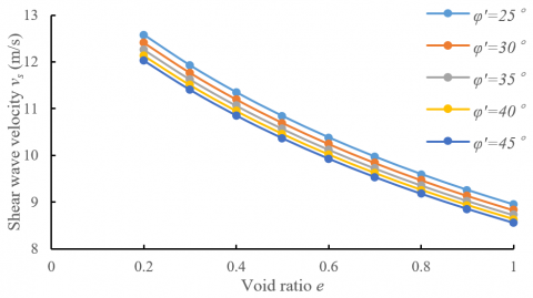
Figure 1 presents the variations of shear wave velocity of the ERA with effective internal friction angles under each void ratio. It can be seen that, when the internal friction angle remained the same, the void ratio exerted a great impact on shear wave velocity: the shear wave velocity dropped by 28.86%, as the void ratio grew from 0.2 to 1.0. It can also be seen that the variation of internal friction angle has little impact on shear wave velocity: as the internal friction angle widened from 25° to 45°, the shear wave velocity only decreased by 4.38%.
Figure 1. The variations of shear wave velocity with effective internal friction angles
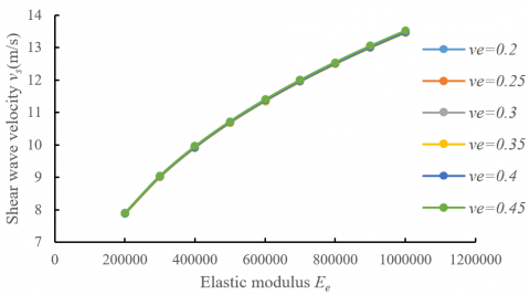
Figure 2 shows the variations of shear wave velocity of the ERA with elastic moduli under each Poisson’s ratio. It can be seen that, when the Poisson’s ratio remained the same, the elastic modulus had a great effect on shear wave velocity: the shear wave velocity increased by 41.52%, as the elastic modulus rose from 2GPa to 10GPa. It can also be seen that, when the Poisson’s ratio changed, the shear wave velocity curves at different elastic moduli basically overlapped each other, indicating that the Poisson’s ratio had little effect on shear wave velocity.
Figure 2. The variations of shear wave velocity with elastic moduli
Figure 3 describes the variations of shear wave velocity of the ERA with the PSCCs under each coordination number. It can be seen that, when the coordination number remained constant, the PSCC had a great impact on the shear wave velocity: the shear wave velocity increased by 55.28%, as the PSCC grew from 0.2 to 1.0. It can also be seen that, the coordination number had little impact on shear wave velocity: the shear wave velocity merely swelled by 9.82%, as the coordination number increased from 11 to 15.
Figure 3. The variations of shear wave velocity with PSCCs
Shear wave velocity is an important dynamic parameter that can well characterize the structure of the ERA, and manifest the microscale arrangement and connection between particles. Inspired by the microparticle contact theory, the PSCC was introduced to derive the equivalent shear modulus of the ERA. Then, the calculation formula for shear wave velocity was obtained by substituting the equivalent shear modulus into the microscopic equivalent model. After that, the impacts of effective internal friction angle, void ratio, elastic modulus, and PSCC on shear wave velocity were analyzed in details. The main contributions are as follows:
(1) Drawing on theories of loose medium mechanics and microparticle contact, the equivalent particle radius and the PSCC were introduced to obtain the 3D stress-strain relationship of the ERA, in view of the previous results on microstructure, constitutive relationship, and contacting equal-diameter spheres in granular mixtures. On the microscale, the ERA was treated as a set of randomly stacked spheres, which are equivalent to soil and rock particles in the ERA and have the same radius and material properties. Based on the macroscopic relationship between shear modulus and shear wave velocity of the ERA, the calculation formulas were derived for shear modulus and shear wave velocity on the microscale.
(2) The effective internal friction angle, Poisson’s ratio, and coordination number of the ERA have little influence on shear wave velocity, while the void ratio, elastic modulus, and PSCC have great impact on shear wave velocity.
To obtain more intuitive and accurate data, the future research will carry out more tests on the elastic modulus and PSCC of ERA particles, and better theorize the effects of the two parameters on shear wave velocity.
The paper was supported by Jiangxi Youth Science Fund Project (Grant No.: 20171BAB216042), and Science and technology project of Jiangxi Provincial Transportation Department (Grant No.: 2019Q0027).
[1] Chang, W.J., Phantachang, T. (2016). Effects of gravel content on shear resistance of gravelly soils. Engineering Geology, 207: 78-90. https://doi.org/10.1016/j.enggeo.2016.04.015
[2] Xu, W.J., Hu, L.M., Gao, W. (2016). Random generation of the meso-structure of a soil-rock mixture and its application in the study of the mechanical behavior in a landslide dam. International Journal of Rock Mechanics and Mining Sciences, 86: 166-178. https://doi.org/10.1016/j.ijrmms.2016.04.007
[3] Chandler, R.J. (1973). The inclination of talus, arctic talus terraces, and other slopes composed of granular materials. The Journal of Geology, 81(1): 1-14. https://doi.org/10.1086/627804
[4] Savely, J.P. (1990). Determination of shear strength of conglomerates using a caterpillar D9 ripper and comparison with alternative methods. International Journal of Mining and Geological Engineering, 8(3): 203-225. https://doi.org/10.1007/BF01554042
[5] Xu, W., Xu, Q., Hu, R. (2011). Study on the shear strength of soil-rock mixture by large scale direct shear test. International Journal of Rock Mechanics and Minging Sciences, 48(8): 1235-1247. https://doi.org/10.1016/j.ijrmms.2011.09.018
[6] Sun, H.F., Yang, Z.K., Xing, M.X., Ju, Y., Yang, Y.M. (2012). CT Investigation of fracture mechanism of soil-rock mixtures. In Applied Mechanics and Materials, 204: 67-71. https://doi.org/10.4028/www.scientific.net/AMM.204-208.67
[7] Guo, Z., Chen, X., Xu, Y., Liu, H. (2015). Effect of granular shape on angle of internal friction of binary granular system. Fuel, 150: 298-304. https://doi.org/10.1016/j.fuel.2015.02.047
[8] Sahay, P.N. (2013). Biot constitutive relation and porosity perturbation equation. Geophysics, 78(5): L57-L67. https://doi.org/10.1190/geo2012-0239.1
[9] Bathurst, R.J., Rothenburg, L. (1988). Micromechanical aspects of isotropic granular assemblies with linear contact interactions. Journal of Applied Mechanics, 55(1): 17-23. https://doi.org/10.1115/1.3173626
[10] Chang, C.S., Misra, A. (1989). Theoretical and experimental study of regular packings of granules. Journal of Engineering Mechanics, 115(4): 704-720. https://doi.org/10.1061/(ASCE)0733-9399(1989)115:4(704)
[11] Christoffersen, J., Mehrabadi, M.M., Nemat-Nasser, S. (1981). A micromechanical description of granular material behavior. Journal of Applied Mechanics, 48(2): 339-344. https://doi.org/10.1115/1.3157619
[12] Cundall, P.A., Strack, O.D. (1979). A discrete numerical model for granular assemblies. Geotechnique, 29(1): 47-65. https://doi.org/10.1680/geot.1979.29.1.47
[13] Liu, J., Gong, J. (2013). Effect of rock content on the mechanical behaviors of the soil-rock mixtures. In 6th International Conference on Discrete Element Methods, Golden, US.
[14] Minh, N.H., Cheng, Y.P. (2013). A DEM investigation of the effect of particle-size distribution on one-dimensional compression. Géotechnique, 63(1): 44-53. https://doi.org/10.1680/geot.10.P.058
[15] Minh, N.H., Cheng, Y.P., Thornton, C. (2014). Strong force networks in granular mixtures. Granular Matter, 16(1): 69-78. https://doi.org/10.1007/s10035-013-0455-3
[16] de Frias Lopez, R., Ekblad, J., Silfwerbrand, J. (2016). A Numerical Study on the Permanent Deformation of Gap-Graded Granular Mixtures. In Third International Conference on Railway Technology: Research, Development and Maintenance. Civil-Comp Press. https://doi.org/10.4203/ccp.110.15
[17] de Frias Lopez, R., Silfwerbrand, J., Jelagin, D., Birgisson, B. (2016). Force transmission and soil fabric of binary granular mixtures. Géotechnique, 66(7): 578-583. https://doi.org/10.1680/jgeot.14.P.199
[18] Iwashita, K., Oda, M. (2000). Micro-deformation mechanism of shear banding process based on modified distinct element method. Powder Technology, 109(1-3): 192-205. https://doi.org/10.1016/S0032-5910(99)00236-3
[19] Maeda, K., Sakai, H., Kondo, A., Yamaguchi, T., Fukuma, M., Nukudani, E. (2010). Stress-chain based micromechanics of sand with grain shape effect. Granular Matter, 12(5): 499-505. https://doi.org/10.1007/s10035-010-0208-5
[20] Senetakis, K., Coop, M.R., Todisco, M.C. (2013). Tangential load–deflection behaviour at the contacts of soil particles. Géotechnique Letters, 3(2): 59-66. https://doi.org/10.1680/geolett.13.00019
[21] Chung, C.K., Jang, E.R., Baek, S.H., Jung, Y.H. (2014). How contact stiffness and density determine stress-dependent elastic moduli: A micromechanics approach. Granular Matter, 16(1): 23-39. https://doi.org/10.1007/s10035-013-0456-2
[22] Zhou, Y.G. (2007). Shear wave velocity-based characterization of soil structure and its effects on dynamic behavior. Hangzhou: Zhejiang University. College of Architectural and Civil Engineering, 3-5.
[23] Wang, P., Wan, F.G. (1997). Fabric description of ballast bed. Journal of Southwest Jiaotong University, 32(2): 165-169.
[24] Zhong, X., Chang, C.S. (1999). Micromechanical modeling for behavior of cementitious granular materials. Journal of Engineering Mechanics, 125(11): 1280-1285. https://doi.org/10.1061/(ASCE)0733-9399(1999)125:11(1280)
[25] Rothenburg, L., Bathurst, R. J. (1992). Micromechanical features of granular assemblies with planar elliptical particles. Geotechnique, 42(1): 79-95. https://doi.org/10.1680/geot.1992.42.1.79
[26] Zhao, M.J., Huang, W.D., Wei, G. (2006). Detection Technology and Application of Compaction Degree Fluctuation of Highway Soil-Rock Mixed Subgrade. People's Communications Press.
[27] Mindlin, R.D. (1949). Compliance of elastic bodies in contact. Journal of Applied Mechanics, 71: 259-268. https://doi.org/10.1007/978-1-4613-8865-4_24
[28] Digby, P.J. (1981). The effective elastic moduli of porous granular rocks. Journal of Applied Mechanics, 48(4): 803-808. https://doi.org/10.1115/1.3157738