Omar Fethi Benaouda* | Badreddine Babes | Mohamed Bouchakour | Sami Kahla | Azzedine Bendiabdellah
© 2021 IIETA. This article is published by IIETA and is licensed under the CC BY 4.0 license (http://creativecommons.org/licenses/by/4.0/).
OPEN ACCESS
The purpose of the welding operation is to ensure the continuity of the materials to be assembled in large industrial sectors. This study aims to suggest a topology of the Thyristor based three-phase rectifiers applied to the Gas Metal Arc Welding (GMAW) process connected to the grid network, the output currents are controlled and using various pulsed forms such as square, annealing, and spike pulse operations and investigate and compare between the effects of the three references welding currents structures on the welding current, welding voltage, droplet diameter, and welding quality. To have the best pulse operation, the amplitude and frequency are kept the same for all operations, the application of meshing graphs in the references of welding currents structures, welding current, welding voltage, and droplet diameter can illustrate a clear comparison between them. The simulation results show that the square pulse operation is the best among them. The Single-Sided Amplitude Spectrum (SSAS) method is also applied to the welding current and droplet diameter of the three operations under slow and rapid droplet detachment rates to estimate the droplet detachment frequency. The results show the great success of the SSAS in estimating the precise frequency.
gas metal arc welding, three-phase rectifier, grid network, SSAS method, welding current, welding voltage, droplet diameter, detachment frequency
Mastering the behavior of structures and assemblies is a growing necessity for the various sectors; aeronautics; automobile; oil transport… etc. Thorough knowledge of the phenomena occurring in the material used, and the factors influencing its behavior makes it possible to prevent anomalies and to choose the conditions adopted for its use [1, 2].
In the fields of the welding industry, there are many types of welding methods. The Gas Metal Arc Welding (GMAW) process is among the most prominent of these methods for several reasons: including the high adequacy in implementation at different thicknesses of the blanks to be welded, and most importantly, the possibility of adapting to the automatic implementation. Welding joints require some mechanical rigidity that depends on the control of the weld dimensions by controlling the amount of molten metal to improve the quality of welding and avoid welding defects [3, 4].
The fusion of the wire and the transfer into the arc can be carried out in different ways depending on the nature of the shielding gases, the voltage and the intensity of the arc. The different so-called spontaneous transfers obtained thanks to generators providing a DC voltage and current (50 - 650 A). It also addresses the forced transfer regimes resulting from the use of particular waveforms (use of two intensity levels, use of a source of variable polarity) [5, 6].
In the GMAW process, it can be said that the transformation of the welding wire into molten droplets, heading to the workpiece, is governed by the phenomenon of heat transfer [7, 8].
The GMAW process has four welding modes including the short-circuit, the globular, the spray, and the rotating vein mode, also other intermediate modes among the mentioned previously.
In the spray mode, the welding current range takes medium values, the molten wire gives spherical droplets, their diameter is less or equal to that of the welding wire because of the steady and regular smelting of the metal [9].
Furthermore, this mode maintains the workpiece intact due to low heat transfer; i.e., the workpiece is rarely burned or penetrated.
In the welding process, the converters such as rectifier, inverter, and chopper are the used sources of arc current and voltage.
In this study, two rectifiers based on thyristor switches are included to feed the GMAW process.
The thyristor switches are chosen because they have acceptable commutation frequency [10].
Even though, the three-level rectifier gives similar efficiency to a couple of two-level rectifiers that are connected in cascade, however, the cascade topology is more preferred because of easier faults diagnosis and lower cost of maintenance [11], and lower applied stress on the semi-conductor (Thyristor) and better power energy output [12, 13].
To feed the GMAW, the grid network must be connected to two-level rectifiers, and the output rectified current is controllable. The rectified current is the same as the reference welding current.
In this paper, the comparative study has been performed between dynamic response waveforms of welding current, welding voltage and droplet diameter according to the variables of the reference signals of welding currents under deferent pulsed modes in one hand, in the other hand, to estimate the droplet detachment frequency, The Single-Sided Amplitude Spectrum (SSAS) method is applied.
This publication is divided into several parts:
In the first part, nonlinear modeling of the GMAW process with its parameters is done.
The second part, make a connection between a couple of two-level rectifiers and the grid network with controlling of rectified current according to the reference current to feed the GMAW process.
In the third part, three pulse operations of the reference welding current are applied in the GMAW process and compared to know the behavior of welding current, welding voltage, and droplet diameter by the help of meshing graphs.
In the last part, estimating the droplet detachment frequency by using the SSAS method; by capturing the welding current, this method transforms the signal from the time domain to the frequency domain in real-time to overcome the use of the expensive ultra-rapid camera.
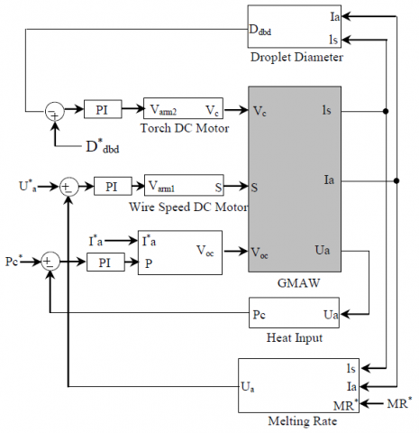
In this section, several equations are used to describe the GMAW process steps from welding wire to the workpiece, in which the GMAW process is modeled according to a set of inputs and outputs to facilitate the GMAW process control and sensing, Figure 1 shows an illustration of schematic block diagram of the GMAW process based on closed-loop.
Table 1 shows an explanation of the remaining parameters with their units, as these parameters included in Eqns. (3) and (4) in order to control the GMAW process in Figure 1.
Figure 1. GMAW process based on closed-loop with the control of melting rate, welding current, welding voltage, and metal droplet diameter
Table 1. Parameters of the GMAW process nonlinear model used in the simulations (Novin Sazan co-manufacturing system)
|
Nomenclature |
Symbol |
Value (unit) |
|
Weld wire DC motor time constant |
tm1 |
50× 10-3 (S) |
|
Weld wire DC motor steady-state gain |
Km1 |
1.0 (mv-1 S-1) |
|
Torch DC motor time constant |
tm2 |
80× 10-3 (S) |
|
Torch DC motor steady-state gain |
Km2 |
1.0 (mv-1 S-1) |
|
Angle of conducting zone with a drop |
q |
90 (°) |
|
Surface tension of liquid steel (Steel) |
g |
1.2 (Nm-1) |
|
Melting rate constant 1 |
C1 |
3.3× 10⁻¹⁰ (m-3 S-1 A-1) |
|
Melting rate constant 2 |
C2 |
0.78× 10⁻¹⁰ (m-3 S-1 W-1A-2) |
|
Drag coefficient |
Cd |
0.44 |
|
Density of the plasma (Argon gas) |
rP |
1.6 (Kg m-3) |
|
Electrode radius |
re |
0.005 (m) |
|
Total inductance (power supply and cable) |
Ls |
306× 10-6 (H) |
|
Total wire resistance (power supply and cable) |
Rs |
6.8× 10⁻³ (W) |
|
Density of the liquid electrode material (Steel) |
re |
7860 (Kg m-3) |
|
Damper constant of drop |
bd |
0.8× 10⁻³ (Kg S-1) |
|
Spring constant of drop |
Kd |
5.3 (Kg S-2) |
|
Permeability of free space Gravity |
µ0 |
4p× 10-7 (H m-1) |
|
Resistivity of the electrode |
r |
0.43 (W m-1) |
|
Shielding gas velocity |
vP |
10 (m s-1) |
|
Constant charge zone |
V0 |
12 (V) |
|
Arc length factor |
Ea |
400 (V m-1) |
|
Contact tip to work piece distance |
lc |
0.025 (m) |
|
Arc resistance |
Ra |
0.0237 (W) |
2.1 The mathematical model for transferring heat and mass to the workpiece
The heat transfer on the length unit of base metal H is defined as the ratio of the total input power P of the heat source in watts to its welding torch travel speed R as shown in the following equation:
$H=\frac{P}{R}=\frac{\eta_{h} I_{a}\left(U_{s}+U_{a}\right)}{R}$ (1)
where, Ua, Ia, Us and hh are arc voltage, arc current, the voltage drop on a stick out, and efficiency of heat transfer to workpiece respectively. Eq (1). is just an approximate mathematical model of what is applied in industry.
Eq. (2) illustrates one of the most important variables of welding, which is the melting rate.
$M_{R}=C_{1} I_{a}+C_{2} \rho l_{s} I_{a}^{2}$ (2)
ls is the stick out length, r is the wire specific electrical resistance and C1 and C2 are constants associated with melting rate MR through Eqns. (1) and (2). The parameters of the electrode (the resistivity and the diameter), contribute greatly to calculate the value of the constants C1and C2. Every welding process and welding wire has its constants (C1 and C2).
The factors of heat and the melting rate directly control the heat and mass transfer to the workpiece, it can be said also that the independence of droplets and the method of transferring molten metal have a great influence on the arc stability, the spread of the amount of molten metal and the thickness of the welding surface [14, 15]. To maintain the transport mode while regulating the emission of molten droplets, the mass and heat transfer amounts must be controlled.
2.2 State-space model of the GMAW process
Based on the two references [16, 17] GMAW modeling is presented in a six-order non-linear model, this model will be completed only after adding welding torch and driving motors of welding wire spool, by this it becomes an eight-order non-linear model:
$\dot{I}_{a}=\frac{1}{L_{s}}\left(V_{o c}-\left(R_{s}+\rho\left(l_{s}+\frac{1}{2}\left(\frac{3 m_{d}}{4 \pi \rho_{e}}\right)^{1 / 3}+x_{d}\right)+R_{a}\right) I_{a}-E_{a}\left(l_{c}-l_{s}\right)-V_{0}\right)$
$\dot{m}_{d}=\rho_{e}\left(C_{1} I_{a}+C_{2} \rho I_{a}^{2} l_{s}\right)$
$i_{s}=S+v_{c}-\left(\frac{C_{1}}{\pi r_{e}^{2}} I_{a}+\frac{C_{2} \rho}{\pi r_{e}^{2}} I_{a}^{2} l_{s}\right)$
$i_{c}=v_{c}$
$\dot{v}_{d}=\frac{F_{T}-k_{d} x_{d}-b_{d} v_{d}}{m_{d}}$
$\dot{x}_{d}=v_{d}$ (3)
where,
$\dot{V}_{c}=\frac{1}{\tau_{m 2}}\left(K_{m 2} V_{a r m 2}-v_{c}\right)$ and $\dot{S}=\frac{1}{\tau_{m 1}}\left(K_{m 1} V_{\text {arm } 1}-S\right)$ (4)
md is droplet mass, vd is droplet velocity, xd is droplet displacement, vc is torch speed, Vam1 is armature voltage of welding wire DC motor, Varm2 is armature voltage of the torch DC motor, FT is a resultant force affecting droplet and Voc is the open-circuit voltage.
From Eq. (3), it can be said that the open-circuit voltage Voc, torch speed vc and wire speed S are the inputs to the system of the GMAW process, the stick out length ls, welding current Ia are the outputs to the system of the GMAW process. The outputs of Eq. 4 (wire and torch speed) are considered as the input to the GMAW process.
The detailed descriptions about forces affecting droplet and its detachment have been given in references [18, 19].
Eq. (5) shows the amount of stick-out length much greater than the amount of melted welding wire.
$\frac{1}{2}\left(\frac{3 m_{d}}{4 \pi \rho_{e}}\right)^{1 / 3}+x_{d} \prec l_{s}$ (5)
It is possible to rely on the approximation shown in Eq. (6) to determine the arc current value. The electrode electrical resistance Re is:
$R_{e}=\rho\left(l_{s}+\frac{1}{2}\left(\frac{3 m_{d}}{4 \pi \rho_{e}}\right)^{1 / 3}+x_{d}\right) \approx \rho l_{s}$ (6)
The dynamics of the current is written as follows:
$\dot{I}_{a}=\frac{1}{L_{s}}\left(V_{o c}-\left(R_{s}+\rho l_{s}+R_{a}\right) I_{a}-V_{0}-E_{a}\left(l_{c}-l_{s}\right)\right)$ (7)
The heat input can be written as follows:
$P_{c}=I_{a} U_{c t}=I_{a}\left(U_{s}+U_{a}\right) \approx \rho l_{s} I_{a}^{2}+R_{a} I_{a}^{2}+E_{a} l_{c} I_{a}-E_{a} l_{c} I_{a}+V_{0} I_{a}$ (8)
where, Uct is the voltage of contact tip to work piece distance, as Eq. (8) depends on the integral of the welding current value as mentioned in the Eq. (7).
When the static forces of detachment (gravity Fg, electromagnetic forces Fem and the plasma drag forces Fd) are less than the static forces of attachment (surface tension force Fg), that means that the static theory of equilibrium conditions have been achieved [20, 21].
The resulting force equation affecting the droplet is written according to the force balance model (MFBM) as follows [22]:
$F_{T}=F_{g}+F_{e m}+F_{d}+F_{m f}$ (9)
where, Fmf the momentum flux force.
The mass of the molten metal is the basis of the gravity force Fg, when welding takes a flat shape.
$F_{g}=\frac{4}{3} \pi r_{d}^{3} \rho_{d} g$ (10)
With g is the gravity constant, rd is the density of the drop and rd is the radius of the drop. The drag force Fd is written by the following equation:
$F_{d}=\frac{1}{2}\left(c_{d} A_{d} \rho_{p} v_{p}^{2}\right)$ (11)
where, Ad is the area of droplet hit by the shielding gas, vP is the shielding gas velocity, rP is the density of the plasma and cd is the drag coefficient.
Eq. (12) shows the momentum flux Fmf [23].
$F_{m f}=\frac{\mu_{0} I_{a}^{2}}{4 \pi}\left[\frac{1}{\alpha^{2}}-\left(1-\sqrt{1-\frac{1}{\alpha^{2}}}\right)^{2}\right]$ (12)
where, rd/re is defined as a (rd is droplet radius and re is the weld wire radius), m0 is the permeability of the free space.
Based on equality between the detaching preventive force Fg and the total static forces of detachment FT, the diameter of the droplet before the detachment Ddbd can be determined. The liquid metal has a surface tension coefficient defined as g.
$F_{T}=F_{\gamma} \rightarrow F_{e m}=F_{\gamma}-F_{g}-F_{d}-F_{m f}$ (13)
The total electromagnetic force can be defined by the following equation:
$F_{e n}=\frac{\mu_{0} I_{a}^{2}}{4 \pi}\left[\ln \left(\frac{r_{d} \sin \theta}{r_{e}}\right)-\frac{1}{4}-\frac{1}{1-\cos \theta}+\frac{2}{(1-\cos \theta)^{2}} \ln \left(\frac{2}{1+\cos \theta}\right)\right]$ (14)
where, q is the angle of the arc-covered area. By substituting for Fem from (13), (14) can be written as:
$\frac{\mu_{0} I_{a}^{2}}{4 \pi}\left[\ln \left(\frac{D_{d b d} \sin \theta}{r_{e}}\right)-\frac{1}{4}-\frac{1}{1-\cos \theta}+\frac{2}{(1-\cos \theta)^{2}} \ln \left(\frac{2}{1+\cos \theta}\right)\right]$$=F_{\gamma}-F_{g}-F_{d}-F_{m f}$ (15)
Eq. (16) shows the detaching droplet diameter size:
$D_{d b d}=\frac{2 r_{e}}{\sin \theta} e^\left({\frac{F_{y}-F_{g}-F_{d}-F_{m f}}{\frac{\mu_{0} I_{\alpha}^{2}}{4 \pi}}-K_{1}}\right)$ (16)
Through the above, the moment of the droplet detachment is not determined, to clarify this, the following condition can be used [24, 25]:
$F_{T} \succ F \gamma$ (17)
After each droplet detachment, the initial conditions are defined as follows:
$I_{a}=I_{a}$
$l_{s}=l_{s}$
$x_{d}=0$
$V_{d}=0$
$m_{d}=0.5 m_{d}\left(1+\frac{1}{1+e^{-k_{2} v_{d}}}\right)$ (18)
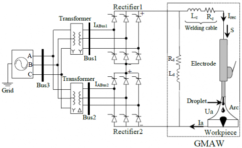
Figure 2 shows a schematic diagram of the Grid-GMAW process. Two three-phase rectifiers connected to the GMAW, to obtain a great value of the arc current Ia. one transformer is connected in star-star to Bus1 and the other, delta-star to Bus2.
Figure 2. The electrical model of Grid-GMAW Process
3.1 Simulation results
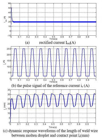
Figure 3. Simulation results of GMAW process based on closed-loop), under annealing pulse operation
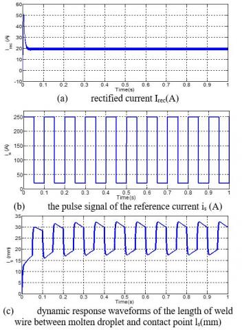
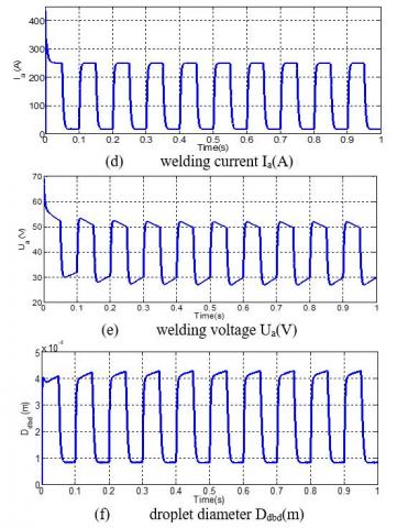
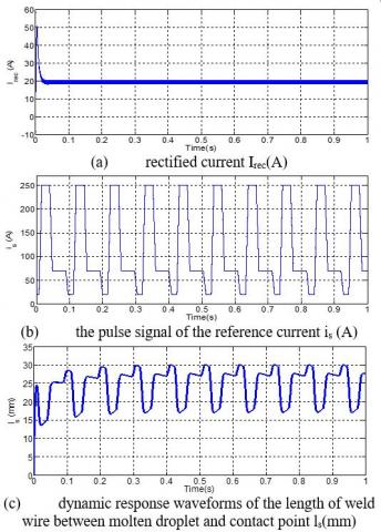
Figure 4. Simulation results of GMAW process based on closed-loop), under square pulse operation
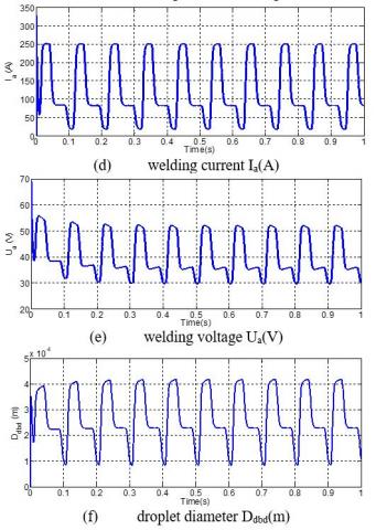
Figure 5. Simulation results of GMAW process based on closed-loop), under spike pulse operation
3.2 Discussion of results
Through the simulation results of Figure 3, the rectified current (Irec) stabilizes at the value of 20A, so this value is identical to the reference value. After applying the annealing pulse operation, its amplitude varies between 20A and 250A in the interval of the frequency of 0.1s, the length of weld wire between molten droplet and contact point ls(mm) fluctuates between 16.75 and 30.82mm; which means that its length decreases by 28.36mm in 0.1s. The welding current (Ia) takes 0.03s to move from 20A to 250A, the current (Ia) reaches the maximum current value in 0.02s. Up and down welding current (Ia) takes up 60% of the total period of a single annealing pulse; where it takes 0.06 seconds between forming and releasing the molten metal drop, the welding voltage Ua(V) fluctuates between 28.87V and 52.64V.
The droplet diameter has two stages, the first stage is called the construction process, during which, the diameter increases by a value of 0.33mm, after this, it is released immediately to enter a new stage called detachment process.
In Figure 4 after applying square pulse operation, although this pulse differs from the previous one in terms of structure, they are equated in amplitude and frequency to conduct a comparative study between them and identify the impact of each of them on the dynamic response of the outputs GMAW process. While maintaining the rectified current (Irec) at the value of 20A, the square pulse amplitude varies from 20A to 250A at a frequency of 10 Hz with the pulse width equal to 50% of the period, the length of ls(mm) fluctuates between 17.48mm and 32.35mm; to melt around 29.74mm within 0.1s.
During 0.015s, the welding current (Ia) varies from 20 to 250A. The welding voltage Ua(V) fluctuates between 26.90V and 51.94V. The droplet is detached when its diameter increases by 0.34 mm to reach 0.43mm. Regarding Figure 5, after the application of the spike pulse on the GMAW process, the results show different behavior compared to the previous ones, the amplitude of the spike pulse is (A) changes from 20 to 250A during 0.008s, then decline from 250A to 70A during another 0.008s, after that, it maintains at 70A during 0.04s, and then it returns to the initial value within 0.008s.
The stick out length ls(mm) varies from 17.05 to 30.06mm; where the wire is consumed by 27.38mm within 0.1s.
The welding current (Ia) varies from 20 to 250A during 0.02s, it maintains at 250 and 70A for 0.01s and 0.025s, respectively. Therefore, these two periods are necessary to form a droplet. The welding voltage Ua(V) oscillates between 29.86V and 52.63V. When the droplet diameter Ddbd reaches 0.41 mm, it loses 46% of its total weight to become 0.22 mm diameter; this means that the detachment process is done through two steps due to the gradual decrease of the welding current (Ia).
For a comparative study between the operations of the previously mentioned pulse, with frequencies and amplitudes are kept constant. The graphs of welding current as a function of the welding voltage and graphs of the diameter of the droplets as a function of the length of the welding wire are shown in Figure 6 and Figure 7 respectively.
4.1 Simulation results
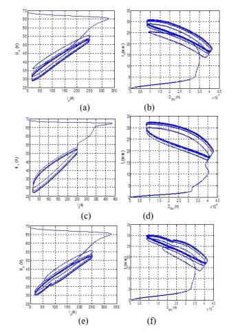
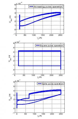
Figure 6. Dynamic response waveforms: (a), (c) and (e): welding current as a function of welding voltage, (b), (d) and (f): droplet diameter Ddbd(m) as a function of the length of weld wire ls(mm), under: (a) and (b): annealing pulse operation, (c) and (d): square pulse operation, (e) and (f): spike pulse operation
4.2 Discussion of results
The graphs of Figure 6, in meshing graphs, the welding voltage as a function of welding current are chosen because they are very important electrical parameters to determine the welding characteristics.
The choice of the droplet diameter as a function of the length of welding wire between the molten droplet and contact point is caused by the heat transfer from the melted wire into a spherical droplet with considering the droplet as an output and the wire as an input, the quality of welding can be determined from the relationship between them.
In part (a) of Figure 6, the change of welding voltage as a function of welding current forms a meshing interval; The interval of welding voltage varies from 28 to 52V, while the welding current varies from 20 to 250A. The formed mesh width of the annealing pulse operation is less than that resulting from the square and spike pulses operations as shown in parts (c) and (e) respectively.
In part (b) of Figure 6, the droplet diameter varies from 0.08 to 0.4mm and the weld length varies from 16 to 30mm, these two intervals form a mesh width are less than those of square and spike pulses operations as shown in parts (d) and (f) respectively.
From the above results, it can be said that the mesh width of the square pulse operation is the widest over the other pulses operations.
4.3 Simulation results
Figure 7. Dynamic response waveforms of droplet diameter Ddbd(m) as a function of the pulse signal of the reference current is(A) under three pulses operations
4.4 Discussion of results
To enrich more the discussion, in Figure 7, the droplet diameter as a function of the pulse signal of the reference current shows more clear change in the mesh width between the three pulses operations compared to Figure 6 as shown in parts (a), (b), (c), (d), (e) and (f).
4.5 Simulation results
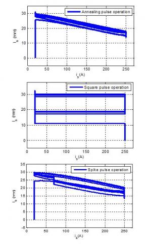
Figure 8. Dynamic response waveforms of the length of weld wire between molten droplet and contact point ls(mm) as a function of the pulse signal of the reference current is(A) under three pulses operations
4.6 Discussion of results
Figure 8 shows the change of the weld wire length as a function of reference current signal pulse is(A) under three pulses operations, the formed mesh width by applying the annealing pulse operation is narrow compared to the other operations, Furthermore, the square pulse operation mesh width is the largest among the spike and annealing pulses operations.
It can be said that the results obtained in Figure 7 and Figure 8 have the same descriptive significance to determine the mesh width, although the obtained results in the Figure 7 and Figure 8 differ.
4.7 The relationship between the width and shape of the mesh with the welding quality
From the previous discussion, it can be said that not only the width of the mesh that determines the welding quality but also the shape of the mesh.
In annealing pulse operation shown in Figure 7, when pulse signal of the reference current starts to reach 250A, the percentage of the droplet formation reaches 85%, this percentage is around 69% in the spike pulse operation, and complete formation in the square pulse operation. It can be concluded that the fastest process to form 4mm of the droplet diameter is the square pulse operation and then the spike pulse operation and after that the annealing pulse operation.
It is noticed that the time in between the end of the droplet formation and the beginning of the droplet detachment affects on the shape of the mesh; if it is wide and regular, this means that the droplet diameter is uniform and the formation of droplets is fast, and very high welding quality.
In this section, for the precise estimation of droplet detachment frequency, the Single-Sided Amplitude Spectrum (SSAS) method is applied to the welding current droplet diameter.
5.1 Single-Sided Amplitude Spectrum (SSAS)
In signal processing, several techniques are used, including the technique of spectral analysis; it transforms the signal from the time domain to the frequency domain [26, 27]. Joseph Fourier transformed to obtain spectral representation. The following equation shows the Fourier transform I(f) of a signal I(t):
$I_{a}(f)=\int_{-\infty}^{+\infty} I_{a}(t) \cdot e^{-J 2 \pi f} d t$ (19)
The positive aspect of this method is the calculation of the frequency for any periodic signal.
5.2 Simulation results
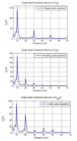
Figure 9. Simulation results of spectral analysis of welding current Ia (A) under three pulses operations (Low frequency)
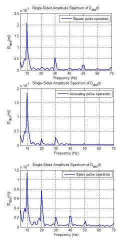
Figure 10. Simulation results of spectral analysis of droplet diameter Ddbd(m) under three pulses operations (Low frequency)
5.3 Discussion of results
From Figure 9 and Figure 10, after applying the SSAS Method, the fundamental frequency of 10 Hz for the welding current and the droplet diameter is estimated.
Estimating the fundamental frequency is very important because it is the same as the droplet detachment frequency.
It can also be said that welding current is a sum of sinusoidal signals; each sinusoidal signal has its amplitude and frequency.
To know the success of the SSAS method under high frequency, the pulse signal frequency of the reference current is(A) is increased for all tested pulse operations, then the drop detachment frequency is estimated by using the spectral analysis of welding current.
6.1 Simulation results
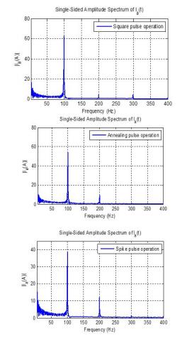
Figure 11. Simulation results of spectral analysis of welding current Ia (A) under three pulses of operations (High frequency)
6.2 Discussion of results
From Figure 11 the amplitude of ½Ia(A)½ varies at the frequencies 100Hz, 200Hz and 300Hz.
Frequencies 200Hz and 300Hz are multiples of 100Hz, which means that the droplet detachment frequency is 100Hz.
From the previous discussion, it can be said the SSAS method proven merit in the estimation of droplet diameter at low and high frequencies in one hand, and the other hand it is inexpensive concerning the ultra-rapid camera.
From the above results and discussions, some concluding remarks can be derived:
When the Gas Metal Arc Welding (GMAW) process is combined with thyristor-based three-phase rectifiers that are connected to the grid network, very satisfactory results are obtained about rectified current, dynamic response waveforms of the welding current, welding voltage and droplet diameter under three pulses operations (annealing, square and spike).
For the comparative study between the three pulses operations applied on the GMAW process, sets of meshing graphs are conducted on:
From the meshing graphs, it can be said that the square pulse operation is found to be the fastest process to form the droplet diameter; furthermore, it satisfies well the requirement of the spray mode welding process.
It is noticed also that as the formation of droplets is fast, the droplet diameter is uniform, the high welding quality.
There are several techniques to determine the droplet detachment frequency, such as the ultra-rapid camera, but it is very expensive, to remedy this, some techniques based on estimation like the Single-Sided Amplitude Spectrum (SSAS) method. In this method, the spectral analysis through the Fourier’s transformation of the welding current is performed under low and high welding frequency under the three pulse operations, very precise estimation is obtained.
For prospects, it would be better to include the multi-level converter with the GMAW process. This will be the scope of a future paper.
This work was supported by the Research Center in Industrial Technologies CRTI, P.O.Box 64, Cheraga 16014 Algiers, Algeria.
[1] Mvola, B., Kah, P., Martikainen, J., Suoranta, R. (2015). State-of-the-art of advanced gas metal arc welding processes: dissimilar metal welding. Proceedings of the Institution of Mechanical Engineers, Part B: Journal of Engineering Manufacture, 229(10): 1694-1710. https://doi.org/10.1177/0954405414538630
[2] Tipi, A.R.D., Sani, S.K.H., Pariz, N. (2015). Frequency control of the drop detachment in the automatic GMAW process. Journal of Materials Processing Technology, 216: 248-259. https://doi.org/10.1016/j.jmatprotec.2014.09.018
[3] Mvola, B., Kah, P., Layus, P. (2018). Review of current waveform control effects on weld geometry in gas metal arc welding process. The International Journal of Advanced Manufacturing Technology, 96: 4243-4265. https://doi.org/10.1007/s00170-018-1879-z
[4] Penttilä, S., Kah, P., Ratava, J., Eskelinen, H. (2019). Artificial neural network controlled GMAW system: Penetration and quality assurance in a multi-pass butt weld application. The International Journal of Advanced Manufacturing Technology, 105: 3369-3385. https://doi.org/10.1007/s00170-019-04424-4
[5] Caimacan, D., Mishchenko, A., Scotti, A. (2017). Assessment of controlled short-circuiting application in filling passes with MIG/MAG double-wire process. Welding International, 31(2): 90-99. https://doi.org/10.1080/09507116.2016.1218604
[6] Wang, Q., Qi, B., Cong, B., Yang, M. (2017). Output characteristic and arc length control of pulsed gas metal arc welding process. Journal of Manufacturing Processes, 29: 427-437. https://doi.org/10.1016/j.jmapro.2017.08.007
[7] Zhang, X., Gao, H., Zhang, G. (2020). Current-independent metal transfer by utilizing droplet resonance in gas metal arc welding. Journal of Materials Processing Technology, 279: 116571. https://doi.org/10.1016/j.jmatprotec.2019.116571
[8] Dos Santos, E.B., Pistor, R., Gerlich, A.P. (2017). Pulse profile and metal transfer in pulsed gas metal arc welding: droplet formation, detachment and velocity. Science and Technology of Welding and Joining, 22(7): 627-641. https://doi.org/10.1080/13621718.2017.1288889
[9] Wang, Z. (2016). A laser back-lighting based metal transfer monitoring system for robotic gas metal arc welding. Robotics and Computer Integrated Manufacturing, 38: 52-66. https://doi.org/10.1016/j.rcim.2015.10.004
[10] Makoschitz, M., Hartmann, M., Ertl, H. (2017). Control concepts for hybrid rectifiers utilizing a flying converter cell active current injection unit. in IEEE Transactions on Power Electronics, 32(4): 2584-2595. https://doi.org/10.1109/TPEL.2016.2570429
[11] Verveckken, J., Silva, F.A., Barros, D., Driesen, J. (2012). Direct power control of series converter of unified power-flow controller with three-level neutral point clamped converter. IEEE Transation on Power Delivery, 27(4): 1772-1782. https://doi.org/10.1109/TPWRD.2012.2200508
[12] Farhadi, M., Fard, M.T., Abapour, M., Hagh, M.T. (2017). DC–AC converter-fed induction motor drive with fault-tolerant capability under open-and short-circuit switch failures. IEEE Transactions on Power Electronics, 33(2): 1609-1621. https://doi.org/10.1109/TPEL.2017.2683534
[13] Zhao, H., Jin, T., Wang, S., Sun, L. (2016). A real-time selective harmonic elimination based on a transient-free, inner closed-loop control for cascaded multilevel inverters. IEEE Transactions on Power Electronics, 31(2): 1000-1014. https://doi.org/10.1109/TPEL.2015.2413898
[14] Shigeta, M., Nakanishi, S., Tanaka, M., Murphy, A.B. (2017). Analysis of dynamic plasma behaviours in gas metal arc welding by imaging spectroscopy. Welding International, 31(9): 669-680. https://doi.org/10.1080/09507116.2016.1223220
[15] Dos Santos, E.B., Kuroiwa, L.H., Ferreira, A.F.C., Pistor, R., Gerlich, A.P. (2017). On the visualization of gas metal arc welding plasma and the relationship between arc length and voltage. Applied Sciences, 7(5): 503. https://doi.org/10.3390/app7050503
[16] Zeng, M., Huang, J., Zhang, Y., Hu, P. (2017). Modeling for GMAW process with a current waveform control method. Journal of Materials Processing Technology, 240: 404-413. https://doi.org/10.1016/j.jmatprotec.2016.10.018
[17] Soltani, S., Eghtesad, M., Bazargan-Lari, Y. (2020). Mass and heat transfer control in the GMAW process utilizing feedback linearization and sliding mode observer. International Communications in Heat and Mass Transfer, 111: 104410. https://doi.org/10.1016/j.icheatmasstransfer.2019.104410
[18] Mousavi Anzehaei, M., Haeri, M. (2016). Robust estimation of arc length in a GMAW process by an adaptive extended Kalman filter. Transactions of the Institute of Measurement and Control, 38(11): 1334-1344. https://doi.org/10.1177/0142331215587040
[19] Arif, N., Lee, J.H., Yoo, C.D. (2008). Modeling of globular transfer considering momentum flux in GMAW. Journal of Physics D: Applied Physics, 41(19): 1-6. https://doi.org/10.1088/0022-3727/41/19/195503
[20] Sartipizadeh, H., Haeri, M. (2018). Control of droplet detachment frequency in a GMAW process by a hybrid model predictive control. Journal of Dynamic Systems, Measurement, and Control, 140(11): 111008. https://doi.org/10.1115/1.4040251
[21] Singaravelu, D.L., Rajamurugan, G., Devakumaran, K. (2018). Modified short arc gas metal arc welding process for root pass welding applications. Materials Today: Proceedings, 5(2): 7828-7835. https://doi.org/10.1016/j.matpr.2017.11.463
[22] Anzehaee, M.M., Haeri, M. (2011). Estimation and control of droplet size and frequency in projected spray mode of a gas metal arc welding (GMAW) process. ISA Transactions, 50(3): 409-418. https://doi.org/10.1016/j.isatra.2011.02.004
[23] Wu, C., Zou, D., Gao, J. (2008). Determining the critical transition current for metal transfer in gas metal arc welding (GMAW). Frontiers of Materials Science in China, 2: 397-401. https://doi.org/10.1007/s11706-008-0059-8
[24] Ghosh, P.K. (2017). Concept of pulse current gas metal arc welding process. In: Pulse Current Gas Metal Arc Welding. Materials Forming, Machining and Tribology. Springer, Singapore. https://doi.org/10.1007/978-981-10-3557-9_2
[25] Zhao, Y., Chung, H. (2018). Numerical simulation of the transition of metal transfer from globular to spray mode in gas metal arc welding using phase field method. Journal of Materials Processing Technology, 251: 251-261. https://doi.org/10.1016/j.jmatprotec.2017.08.036
[26] Xu, P., Xu, F. (2019). A real-time spectral analysis method and its FPGA implementation for long-sequence-signals. Measurement Science and Technology, 31(3): 035006. https://doi.org/10.1088/1361-6501/ab53a3
[27] Betta, G., Liguori, C., Pietrosanto, A. (2001). A multi-application FFT analyzer based on DSP architecture. IEEE Transactions on Instrumentation and Measurement, 50(3): 825-832. https://doi.org/10.1109/19.930461