Ali Sabri Abbas | Ayad Ali Mohammed*
© 2026 The authors. This article is published by IIETA and is licensed under the CC BY 4.0 license (http://creativecommons.org/licenses/by/4.0/).
OPEN ACCESS
Morphing airfoils facilitate smooth aerodynamic adaptation devoid of any shortcomings that are inherent to discrete control surfaces. Nonetheless, there are few studies considering the combined effects of leading-edge morphing (LEM) and trailing-edge morphing (TEM), since TEM is mostly beneficial for an increase in lift and over cambering/over separation, while LEM contributes to stabilization of the suction peak and stall delay. Moreover, there is currently no known optimization approach that considers compact representation, global metaheuristic search, structural integrity, and multilevel aerodynamic simulation. In the present study, the CBX framework, which couples Class-Shape Transformation (CST) parameterization, Black Widow Optimization (BWO), and XFOIL and enables a low-fidelity optimization cycle followed by high-fidelity validation via the γ–Reθ SST transition model based on Reynolds-averaged Navier–Stokes equations in ANSYS Fluent, is presented. Specifically, optimal design of the coordinated leading and trailing-edge morphing (CoMpLETE) for the NACA 2412 airfoil maximizing the lift-to-drag ratio at Re = 3.1 × 10⁶ and Mach = 0.13 under arc length, curvature continuity, and volume constraints, ensuring that the strain of the skin does not exceed the allowable level (0.84% change in arc length and 0.63% change in volume), is considered. Furthermore, the Reynolds number sensitivity analysis of the optimal design is carried out for Reynolds numbers from 2 × 10⁶ to 6 × 10⁶. As a result of the optimization, the delay of the stall point by 2°, the increase in the maximal value of the lift coefficient to 1.5386, and the maximum lift-to-drag ratio by more than 30% are achieved due to pressure distribution improvement and delaying boundary layer separation. The numerical results are in good agreement (±2.2%) with the experimental ones.
morphing airfoils, combined leading & trailing-edge morphing, Class-Shape Transformation, Black Widow Optimization, multi-fidelity aerodynamic optimization, γ–Reθ SST transition model, NACA 2412
Constant efforts towards achieving improved aerodynamic efficiency, lower fuel burn, and higher manoeuvrability have brought about significant progress in the study of adaptive aerodynamics. The demand to function well within a wide range of operational environments has been the driver for designing shape-adaptive devices which are capable of changing their shape based on the features of the surrounding fluid environment. In particular, morphing airfoils have emerged as quite a promising concept by providing adaptive capabilities of the aerodynamic shape without experiencing the inherent aerodynamic penalty incurred by conventional control surfaces like flaps and slats [1-4].
Existing approaches to enhance morphing technology have focused on increasing aerodynamic adaptability under structural limitations. Morphing involves changes in the geometry of the surface by continuously deforming it, rather than employing hinges as is the case with conventional systems. Numerous experimental and computational investigations performed over the past decade have proven the high efficiency and effectiveness of morphing techniques in low Reynolds number regimes and unmanned aerial vehicle (UAV) applications [5-7]. Furthermore, the introduction of smart materials and compliant mechanisms in morphing airfoil design provides the necessary control and deformations within acceptable strain levels [8, 9].
Among morphing strategies, trailing-edge morphing (TEM) is the most common technique for changing camber to achieve higher aerodynamic performance. Many studies have shown that an optimized TEM greatly increases the lift coefficient and the lift/drag ratio, especially before stalling [7, 10, 11]. Leading-edge morphing (LEM), in contrast, stabilizes the suction peak and delays stall at high angles of attack, improving stability and reducing sensitivity to environmental influences [12-14]. Building on these single-edge concepts, coordinated leading & trailing-edge morphing (CoMpLETE) has been proposed to combine their advantages within a single adaptive surface [15, 16].
These two single-edge mechanisms act on different parts of the flow field and are subject to opposite limitations. TEM creates additional lift due to a higher camber, but a large camber increase causes an even steeper adverse pressure gradient on the suction side that increases the viscous drag and promotes separation. LEM, in turn, modifies the suction maximum and radius of the leading edge, which reduces the pressure peak and delays stall but does not allow any meaningful lift gain until moderately large angles of attack. Thus, trailing and leading morphing are two complementary concepts because each one has its disadvantages, which are covered by the strength of the other approach. The complementarity becomes the foundation for implementing the concept of coordinated morphing, where simultaneous modification of the two morphing regions allows lifting the wing to create additional lift from higher camber while keeping attached flow around the leading edge, thus expanding the range of usable angles of attack. However, no detailed analysis of the coordinated morphing was presented in prior literature.
The application of the proposed approach requires adequate geometric representation and an efficient method of optimization search. Parametric Class-Shape Transformation (CST) description of the complex geometry with a small number of design variables while keeping geometric smoothness [17, 18] has proven to be an effective tool in the aerodynamic design of aircraft. Multi-modal non-linear design tasks have been efficiently tackled with heuristic methods like genetic algorithms (GAs), particle swarm optimization (PSO), and differential evolution [19-21]. Recently, a new meta-heuristic method, the Black Widow Optimization (BWO) algorithm, demonstrated its ability to balance between exploring unknown design space and exploiting already found solutions [22-24], showing its potential in aerodynamic shape optimization, structural design, and energy systems design. Finally, it should be mentioned that the quality of evaluation is an important issue in the optimization loop because rapid panel codes like XFOIL are useful during iterations but lack precision in the case of significant separation, while the γ-Reθ SST RANS model provides high accuracy at a cost of high computational complexity for the purpose of direct search [25-27].
However, despite the maturity of these separate approaches, two major drawbacks of previous works on coordinated morphing exist. First, a number of works are based on evaluation of only several predefined geometries without coupling the description and optimization into a single problem. Therefore, the parameters of morphing are never optimized, and the trade-off between aerodynamic efficiency and feasibility is not established. Although CST parameterization and metaheuristic optimizers are individually well established, they have not been integrated into a single loop that also imposes the arc-length, curvature continuity, and volume constraints required for realizable morphing skins, and the BWO algorithm in particular has not been applied to morphing airfoil design. Second, the aerodynamic model used to drive the optimization and the one used for verification are rarely reconciled, so a single framework combining a fast optimization solver with high-fidelity transition sensitive validation is still lacking.
To address these gaps, the present study develops a unified, Python based optimization framework, denoted CBX, that couples CST parameterization, the BWO algorithm, and XFOIL within a fast low-fidelity optimization loop, with high-fidelity γ–Reθ SST RANS simulations used to validate the optimized designs. The framework is applied to coordinated leading & trailing-edge morphing of the NACA 2412 airfoil. Its purpose is to quantify the aerodynamic benefit of the coordinated strategy and to explain its physical origin through the resulting stall delay, pressure redistribution, and boundary layer behavior.
Unlike existing multi-fidelity airfoil optimization methods, which typically combine solvers of different fidelity to reduce the cost of a single-edge or fixed parameterization problem, the primary contribution of the present framework is not computational speedup in itself but the integration, within one closed loop, of three capabilities that are usually treated separately: a compact CST parameterization of coordinated leading & trailing-edge morphing, a global metaheuristic (BWO) search, and explicit geometric constraints that act as a structural feasibility filter, with the low and high fidelity aerodynamic models used in complementary roles XFOIL to drive the search and γ–Reθ SST RANS to verify it. The main contribution therefore lies in optimization capability and geometric flexibility for the coupled two edge morphing problem, rather than in a new multi fidelity cost reduction scheme.
2.1 Overview of the Python “CBX” multi-fidelity optimization framework
To develop a holistic system for aerodynamic improvement, the proposed optimization framework was implemented in its entirety in Python to ensure interoperability, executability, and repeatability in the optimization of the morphing wings. The proposed optimization framework, as implemented in the Python based ‘CBX’ Optimization Framework, is composed of three computational modules, as follows:
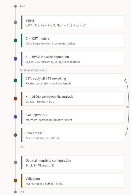
The optimization framework, "CBX," is an acronym for the combination of three modules: CST, BWO, and XFOIL, as shown in Figure 1, which represents the combination of the three modules into a single optimization environment based on Python. In this case, geometry generation, optimization, and aerodynamic evaluation were performed within the same Python code.
To validate the results obtained by the proposed optimization framework, referred to as the “CBX” framework, detailed Reynolds averaged Navier–Stokes simulations were performed for the improved designs obtained by the proposed optimization algorithm using the ANSYS Fluent 2021 code with the γ–Reθ SST transition model.
2.1.1 Vortex generator geometry
The CBX framework was developed using Python as the programming language to ensure smooth integration among the geometry generation, optimization, and aerodynamic analysis phases. Python was used to implement the CST geometry manipulation and update, as well as to apply the constraints. The BWO algorithm was also embedded in the Python environment to update the CST coefficients based on the fitness evaluations. XFOIL was also executed using Python scripts to automate the process of reading the input file and writing the output file to obtain the aerodynamic coefficients in real time without any human intervention. The architecture avoids the problem of inconsistency in the data transfer process among different software tools. It can be used to implement the entire process in a closed loop, automated manner.
Figure 1. Airfoil optimization methodology
2.2 Morphing geometry parameterization using Class-Shape Transformation
2.2.1 Class-Shape Transformation formulation
The morphing airfoil geometry was parameterized using the CST method to ensure a smooth geometry and compact representation using a limited number of design variables. The nondimensional vertical coordinate ζ(ψ) is expressed as follows:
$\zeta(\psi)=C_{N_2}^{N_1}(\psi) S(\psi)+(1-\psi) \zeta_{L E}+\psi \zeta_{T E}$ (1)
where, ψ$\in$[0,1] is a nondimensional chordwise coordinate.
The class function is defined as:
$C_{N_2}^{N_1}(\psi)=\psi^{N_1}(1-\psi)^{N_2}$ (2)
For subsonic airfoils, N1 = 0.5 and N2 = 1 enforce a rounded leading edge and sharp trailing edge.
The shape function is represented by Bernstein polynomials as follows:
$S(\psi)=\sum_{i=0}^n A_i B_i(\psi)$ (3)
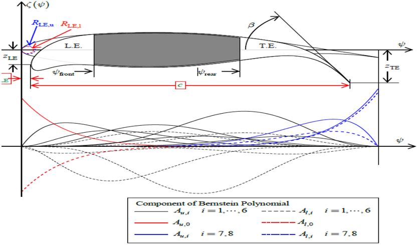
The geometric interpretation of the CST parameters, including the leading edge radius RLE and the trailing edge boat tail angle β, is shown in Figure 2.
Figure 2. The geometric parameters describing the class/shape transformation (CST) airfoil and the corresponding Bernstein polynomial of the baseline shape
2.2.2 Geometric constraints and structural feasibility
To ensure that the optimized geometries correspond to physically realizable morphing skins, three geometric constraints were imposed on every candidate configuration: arc-length preservation, curvature continuity, and volume conservation. The upper & lower surfaces were defined independently to allow coordinated leading & trailing edge morphing, and each constraint has a direct structural interpretation.
The arc-length constraint represents the finiteness of the passive morphing skin extensibility. In a compliant morphing structure, the skin forms a continuous flexible film, in contrast with hinged panels in an actuated structure; therefore, a difference between the arc length in baseline and deformed configurations reflects membrane strain in the skin. Restriction on the approximate constancy of the arc length prevents the strain of the skin from exceeding the limit that can be achieved for elastomeric skin, MFC actuators, and compliant mechanisms before their yielding and buckling. The optimum arc length change in the case of the CoMpLETE configuration was equal to 0.84%, which is within the interval of typical tolerable values of skin strain (1–3%).
A restriction on the curvature continuity prevents the optimizer from producing geometrically allowable but not physically feasible configurations, e.g., kinks, cusps, or points of discontinuity of derivative on interfaces between fixed and morphing surfaces. The physical sense is that the jump in curvature would mean the appearance of a bending moment which cannot exist on a continuous surface. Such an abrupt change would lead to separation of flow which cannot be manufactured as a surface. Thus, enforcement of curvature continuity ensures geometrically feasible skin deformation and real aerodynamic behavior of the shape predicted.
The volume conservation constraint preserves cross-sectional area of the airfoil within a narrow margin due to the near incompressibility of the internal structure and/or internal actuation system, which should also occupy the airfoil volume. This is required to prevent the optimizer from increasing camber through artificial expansion or contraction of the section, which are not feasible in practice. In the case of the optimum configuration, the volume change was 0.63%, which means that the section was deformed shape-wise, not volume-wise.
Instead of reducing the design space significantly, the constraints work as a feasibility filter that rejects unphysical regions of the search domain, leaving the aerodynamically optimal region untouched. One can see from the results that despite those constraints, the optimizer managed to obtain a stall delay angle of 2°, the maximum lift coefficient of 1.5386, and an increase in maximum lift to drag ratio (L/D) ratio of more than 30%, while changes in arc-length and volume were below 1%. Thus, those constraints help to exclude unrealistic deformations while not preventing achievement of aerodynamically highly efficient, structurally feasible deformations.
2.3 Black Widow Optimization
The choice of the BWO algorithm was made due to specific properties of the complex morphing aerodynamic problem rather than general metrics of the efficiency of the optimizer. In particular, the design landscape is nonlinear and multimodal; the dependence of the L/D ratio on leading- and trailing-edge deflections and morphing lengths is not monotonous; and the domain has boundary constraints in the form of arc length, curvature, and volume limitations, resulting in nonlinearity and discontinuity between feasible and infeasible designs. In such landscapes, there is a danger of getting the optimizer trapped in local optima, which makes the preservation of population diversity crucial throughout the search process.
Compared to popular GAs and PSO, which are frequently employed in the field of airfoil optimization [19-21], the Black Widow algorithm provides some advantages under these conditions. First, at the cannibalism stage, each iteration intentionally removes the weakest members of the population to focus on promising parts of the design landscape and speed up the convergence process, whereas the subsequent procreation and mutation stages still provide sufficient diversification and help to prevent convergence to a local optimum, premature stagnation and collapse of the swarm toward the single global optimum found, characteristic of PSO in such strongly multimodal landscapes. Secondly, each fitness function evaluation in the current optimization framework involves an iterative computation with XFOIL. Thus, the total amount of aerodynamic evaluations takes up most of the total cost. Aggressive removal of poor solutions in BWO guarantees a sufficiently fast convergence of the algorithm within a fixed budget, which is more efficient in terms of computational cost compared to GA, requiring larger populations and more iterations to reach similar results.
These properties are consistent with recent applications of BWO to other nonlinear engineering problems of shape, structure, and energy system design, where it demonstrated the competitiveness of the convergence to optimal results compared to standard metaheuristics [22-24]. The suitability of BWO for the current problem is additionally validated in Section 2.6.1 based on the repeatability analysis of the maximum L/D ratio obtained in three independent runs using different random seeds, which does not exceed 1.8%.
The BWO algorithm was employed as a global metaheuristic optimizer because of its strong exploration–exploitation balance in multimodal design spaces.
Each candidate solution (widow) is defined as:
$y=\left(y_1, y_2, \ldots, y_{M_{v a r}}\right)$ (4)
The population matrix is of size Mpop × Mvar.
The optimization process consists of the following:
The convergence acceleration mechanism is attributed to the cannibalism stage, which actively removes low fitness candidates.
The fitness function is defined as:
$f=\frac{L}{D}$ (5)
or alternatively, lift maximization depending on the optimization case.
2.3.1 Design variable bounds and constraint handling
The search domain for the optimization search was defined by well-defined geometrical boundaries that ensured the physical validity of morphing configurations. The deflection angle of the leading edge is constrained by:
$\theta_{L E} \in\left[0^{\circ}, 15^{\circ}\right]$ (6)
The trailing-edge deflection angle was limited to:
$\theta_{T E} \in\left[0^{\circ}, 30^{\circ}\right]$ (7)
The morphing lengths were restricted to:
$D_{L E} \in[0.1 \mathrm{c}, 0.4 \mathrm{c}], \quad D_{T E} \in[0.6 \mathrm{c}, 0.9 \mathrm{c}]$ (8)
Additionally, the selected coefficients for the CST were constrained to ±0.1 to ensure a smooth curvature and avoid extreme deformation of the leading-edge radius. To this end, constraints were addressed by applying direct feasibility filtering, in which geometries that failed to satisfy any of the arc length, curvature continuity, or volume constraints were removed from the optimization.
2.3.2 Design variable bounds and constraint handling
The optimization was conducted as a single objective problem. The fitness function was evaluated for a specific angle of attack (AoA = 10°) under Re = 3,100,000 and Mach = 0.13. The selection of the angle of attack was based on the pre-stall flight regime, while the full range of the angle of attack (0°–20°) was considered for aerodynamic analysis purposes only.
2.4 Aerodynamic Evaluation Strategy
2.4.1 Low-fidelity solver (optimization loop)
XFOIL was employed to compute the lift and drag coefficients under the following operating conditions:
•Mach number = 0.13
•Reynolds numbers = 3,100,000
•Angle of attack range = 0°–20°
Transition prediction was enabled to capture the laminar–turbulent effects along the airfoil surface.
A nominal chord length of c = 1 m was adopted for the computational normalization. The Reynolds number was enforced by adjusting the inlet velocity according to [28]:
$R e=\frac{\rho V c}{\mu}$ (9)
This normalizing method retains the aerodynamic similarity criteria while ensuring numerical consistency inside the CFD environment.
It is well known that the accuracy of XFOIL decreases in the presence of massive flow separation at high angles of attack (typically AoA > 15°) owing to the limitations of the coupled panel and boundary-layer formulation [16]. However, in the present study, the optimization objective was evaluated at AoA = 10°, which lies within the pre-stall regime, where XFOIL predictions remain reliable for airfoil performance evaluation.
Moreover, the reliability of the obtained results at high AoA is supported by high-fidelity RANS simulations using the γ–Reθ SST transition model in ANSYS Fluent, which show good agreement with the predicted trends. Hence, the combined use of XFOIL validated by CFD results confirms both computational effectiveness and physical consistency in the aerodynamic calculation.
2.4.2 High-fidelity validation
High-fidelity validation was performed using ANSYS Fluent 2021 by solving steady, incompressible RANS equations with the γ–Reθ SST transition model.
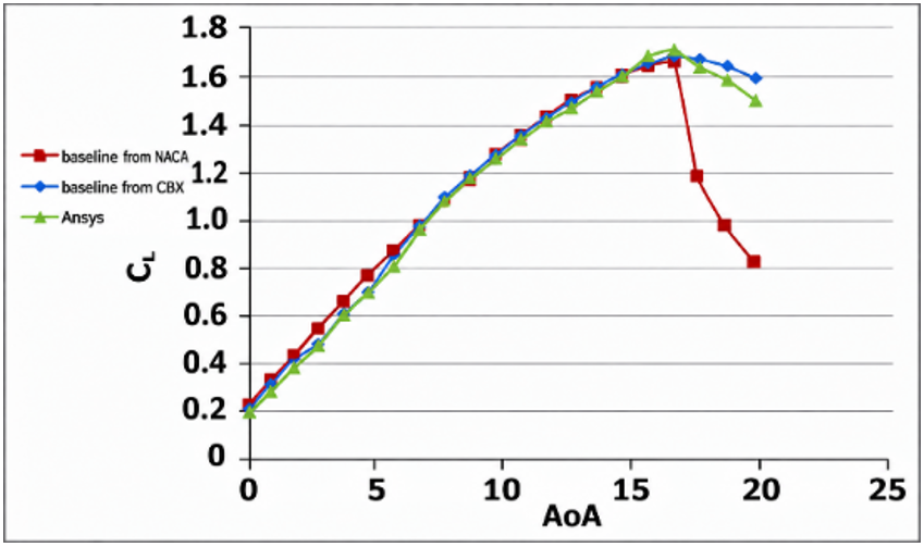
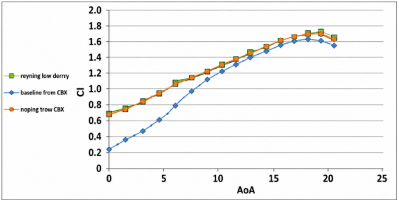
The validation of the numerical setup against experimental data [13] and the results from the CBX for the baseline NACA 2412 airfoil without morphing are presented in Figure 3 (Re = 3,100,000).
The deviation between the numerical and experimental lift coefficients remained below 2.2%, confirming the model reliability.
Figure 3. Comparison of the present numerical values and the experimental data of ref. [13] for the baseline NACA 2412 airfoil, of CL versus the angle of attack, at Mach = 0.13 and Re = 3,100,000
2.4.3 RANS modeling and γ–Reθ SST transition model
The high-fidelity simulations were performed by solving the steady incompressible Reynolds-Averaged Navier–Stokes equations (RANS) coupled with the transition model γ–Reθ SST. This model combines the SST k–ω turbulence formulation with additional transport equations for intermittency (γ) and transition momentum thickness Reynolds number (Reθ), qualifying accurate prediction of laminar–turbulent transition. It has demonstrated high reliability in airfoil analyses, particularly at low to moderate Reynolds numbers, where transition strongly affects boundary layer growth and the behavior of separation. Related to fully turbulent models, it provides improved accuracy in predicting stall onset and aerodynamic performance. The model also confirms consistency with the transition-sensitive XFOIL predictions used in the optimization framework.
It should be noted that panel-based formulations such as XFOIL tend to overpredict peak lift values ($C_{L, \max } \approx 1.720$) prior to stall due to the simplified modeling of massive boundary layer separation. Consequently, XFOIL is utilized strictly as a rapid evaluator within the BWO optimization loop to guide candidate selection, whereas the absolute aerodynamic baseline and optimized performance parameters ($C_{L, \max }=1.5386$) are formally established using high-fidelity $\gamma-R e_\theta$ SST RANS simulations in ANSYS Fluent.
2.5 Numerical setup and grid independence
2.5.1 High-fidelity validation
The computational domain consisted of the following:
•Semicircular inlet boundary (radius = 7.5 c)
•Downstream extension = 15 c
•Velocity inlet boundary conditions
•Pressure outlet boundary condition
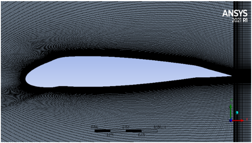
The domain configuration is illustrated in Figure 4.
Standard sea-level air properties were used.
•ρ = 1.225 kg/m³
•μ = 1.7894 × 10⁻⁵ kg/(m·s)
•Chord length c = 1 m
•Inlet velocity V = 45.6 m/s
Figure 4. The structured grid used for the NACA 2412 airfoil
2.5.2 Mesh generation and quality assessment
An unstructured mesh with boundary layer refinement was generated. The structured grid around the airfoil is illustrated in Figure 4.
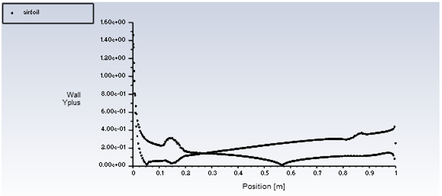
The wall resolution (y+) distribution is illustrated in Figure 5, where y+ ≤ 1 confirms an adequate near-wall resolution for transition modeling.
Figure 5. Wall y+ distribution over NACA 2412 airfoil at various angles of attack of 0°
The mesh quality metrics are summarized in Table 1, including:
•Maximum skewness = 0.18
•Orthogonality = 0.88
•Element quality = 0.87
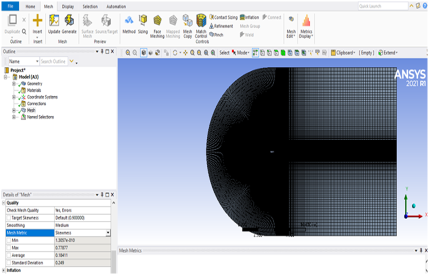
All values were well within the suggested standard [15], which validates the grid adequacy. In addition to the quantitative mesh quality parameters listed in Table 1, Figure 6 shows the spatial distribution of the mesh elements and their skewness values. Figure 6 validates the numerical mesh quality parameters by presenting a smooth transition from the near-wall boundary layer to the far-field region, with no areas of high skewness observed.
Table 1. Properties of the mesh matrices (validation case)
|
Factor |
Value |
Recommended Value [15] |
Status |
|
Skewness |
0.18 |
<0.25 |
Excellent |
|
Orthoginal element |
0.88 |
<0.9 |
Excellent |
|
Element quality |
0.87 |
<0.88 |
Excellent |
Figure 6. Spatial distribution of mesh elements and skewness metrics for baseline NACA 2412 computational domain
2.5.3 Generation of grids and mesh independence
To ensure numerical consistency for the optimized morphing configuration, the same meshing approach used for the baseline NACA 2412 airfoil was adopted for the CoMpLETE airfoil. The computational grid was regenerated for the morphed airfoil, retaining the same near-wall refinement strategy. The computational domain was discretized with approximately 120,000 elements, with local refinement concentrated near the airfoil surface and in the wake region. The height of the first layer was set so that y⁺ did not exceed 1 on the airfoil surface, which is essential for accurate resolution of the boundary layer.
Table 2. Mesh-independence study for the NACA 2412 validation case (AoA = 10°, Re = 3.1 × 10⁶)
|
No. |
Case |
No. of Grid Elements |
CL |
CLdeviation |
|
1 |
Validation case at AoA = [10]° and Re = 3.1 × 10⁶ |
36016 |
1.214 |
0.019769357 |
|
56985 |
1.238 |
0.011308562 |
||
|
87656 |
1.252 |
0.006389776 |
||
|
120000 |
1.26 |
0.001587302 |
||
|
250680 |
1.262 |
0.001792393 |
||
|
514525 |
1.263 |
|
A grid-independence study was carried out for the baseline validation case at AoA = 10° and Re = 3.1 × 10⁶ to confirm that the reported lift coefficient was independent of the mesh resolution. Six successively refined meshes, ranging from 36,016 to 514,525 elements, were compared, as summarized in Table 2. Refinement of the mesh had a progressively smaller effect on the lift coefficient: the relative change in C_L dropped to 0.16% when the mesh was refined from 120,000 to 250,680 elements, and to below 0.08% with further refinement. The mesh of approximately 120,000 elements was therefore selected for all subsequent simulations, as it provided grid-independent results at an acceptable computational cost.
2.5.4 Solver settings and convergence criteria
The steady, two-dimensional simulations were performed in ANSYS Fluent 2021 R1 using a double-precision, pressure-based solver with an absolute velocity formulation, run in parallel on four processes, with air as the working fluid. Turbulence and laminar–turbulent transition were modeled using the four equation γ–Reθ SST transition model, which augments the SST k–ω formulation with transport equations for intermittency (γ) and transition momentum thickness Reynolds number (Reθ). Pressure–velocity coupling was treated with the coupled scheme. Gradients were evaluated using the least-squares cell-based method; pressure was discretized with a second-order scheme; and the momentum, turbulent kinetic energy (k), specific dissipation rate (ω), intermittency, and transition Reynolds number equations were discretized using second-order upwind schemes. Convergence was enforced by requiring the absolute scaled residuals of all transport equations — continuity, x- and y-momentum, k, ω, intermittency, and transition Reynolds number — to fall below 1 × 10⁻⁵.
2.6 Optimization settings
To ensure convergence robustness and computational efficiency, the BWO algorithm parameters were carefully selected based on a balance between exploration capability and convergence stability, as shown in Table 3. A moderate population size (Mpop = 40) was adopted to provide sufficient diversity in the search space while maintaining manageable computational cost. The maximum number of iterations was set to 60, which was found to be sufficient to achieve convergence without unnecessary computational overhead, as confirmed by the convergence history presented in Section 3.6.
The procreation rate (0.6) was selected to maintain an effective balance between generating new candidate solutions and preserving high-quality individuals. The cannibalism rate (CR = 0.45), a key feature of the BWO algorithm, was tuned to enhance convergence speed by eliminating low-fitness solutions while retaining sufficient population diversity. In addition, a mutation rate of 0.2 was employed to prevent premature convergence and ensure adequate exploration of the design space.
Table 3. Black Widow Optimization (BWO) algorithm configuration
|
Parameter |
Value |
Description |
|
Population size (Mpop) |
40 |
Number of candidate solutions |
|
Maximum iterations |
60 |
Termination criterion |
|
Procreation rate |
0.6 |
Crossover proportion |
|
Cannibalism rate (CR) |
0.45 |
Survival threshold |
|
Mutation rate |
0.2 |
Random perturbation intensity |
|
Design variables |
4–8 |
Depending on case |
The number of design variables (4–8) was determined based on the CST parameterization and morphing configuration, ensuring sufficient geometric flexibility while avoiding excessive dimensionality. Overall, these parameter values are consistent with commonly adopted practices in metaheuristic-based aerodynamic optimization and were further validated through the observed stable convergence behavior and repeatability of the optimization results.
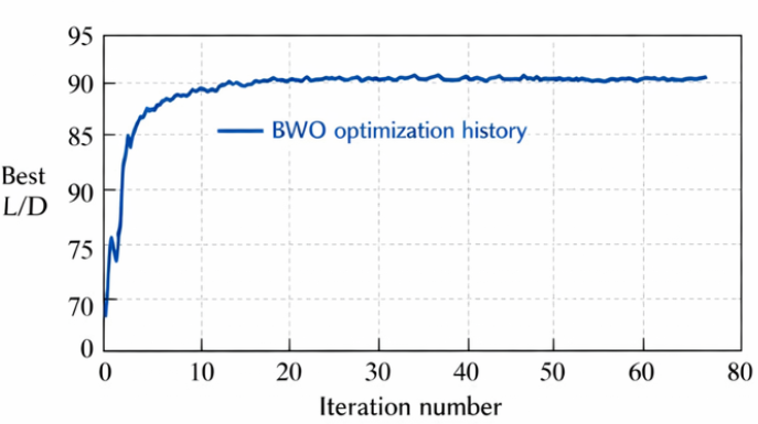
The BWO control parameters listed in Table 3 (procreation and cannibalism rates) were adopted from previously reported applications of the algorithm to nonlinear engineering optimization problems [22-24], where these values provided a reliable balance between exploration and exploitation. The population size and number of iterations were then verified to be sufficient for the present problem: as shown by the convergence history in Section 3.6, the objective value stabilized before the 45th iteration, well within the allotted iterations, confirming that the selected settings ensure convergence at an acceptable computational cost.
2.6.1 Optimization repeatability
To assess the stochastic robustness of the optimization, the optimization was performed three times using different seeds of random numbers. The difference in the maximum lift/drag ratio was less than 1.8%.
This section presents the aerodynamic performance analysis of the proposed CoMpLETE morphing configuration obtained using the CBX optimization framework. The results are presented as parametric aerodynamic performance characteristics, flow field characteristics, and a comparison with those of the baseline airfoil.
3.1 Parametric influence of morphing variables on aerodynamic performance
3.1.1 Geometric configuration and design space exploration
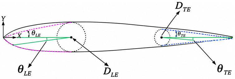
A two-dimensional model of the NACA 2412 airfoil was created as the baseline configuration. The proposed CoMpLETE morphing concept in Figure 7 enables the control of the rotation angles at the leading edge (θLE) and trailing edge (θTE), as well as the morphing positions (DLE and DTE).
Figure 7. Sketch of CoMpLETE airfoil
A systematic parametric sweep was performed by varying one parameter while keeping the remaining variables constant. The aerodynamic response was evaluated over AoA ∈ [0°, 20°] at Mach = 0.13 and Re = 3,100,000.
The stall angle in the present study was defined as the angle of attack corresponding to the maximum lift coefficient (CLmax) prior to a lift reduction exceeding 5%.
These results confirm that the aerodynamic performance improvement of the optimized CoMpLETE configuration originates from the coordinated pressure redistribution and suppression of separation growth.
3.1.2 Influence of leading edge morphing rotation angles (θLE)
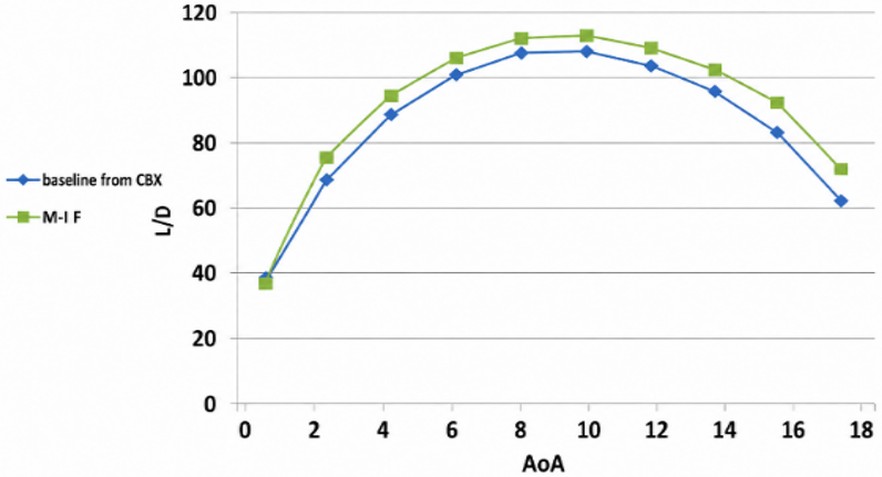
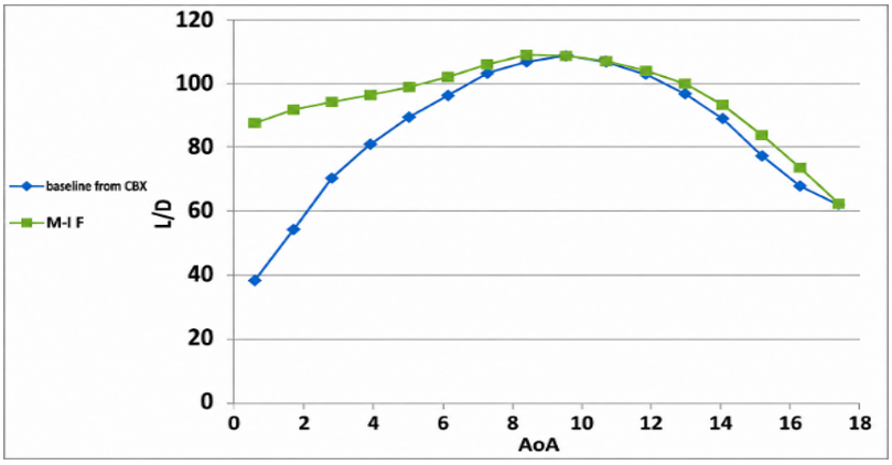
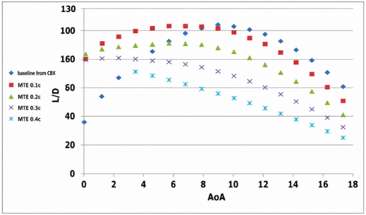
The variation in the L/D ratio with respect to the angle of attack for various leading-edge rotation angles is illustrated in Figure 8. The analysis revealed that the morphing of the leading edge within an optimal range (θLE = 10°) significantly increased the aerodynamic efficiency during the pre-stall flight regime (AoA = 6°–12°). This behavior is associated with the strengthening of the suction peak in proximity to the leading edge, which leads to an increase in flow acceleration and boundary layer stability.
Figure 8. Comparison of original baseline NACA 2412 airfoil and optimized morphed leading-edge airfoil lift/drag ratios versus angle of attack from CBX framework influences of rotation angle, at MLE = 0.2 c, Mach = 0.13 and Re = 3,100,000
Physically, a larger curvature reduces the effect of the adverse pressure gradient, thus increasing the value of pressure recovery. Simultaneously, strong morphing (θLE > 12°) leads to an earlier saturation of pressure values and increased viscous drag, resulting in reduced aerodynamic efficiency at small angles of attack.
These conclusions agree well with recent research that discusses the benefits of optimizing leading-edge deformation to enhance lift generation while maintaining boundary layer stability [12-14].
3.1.3 Influence of leading edge morphing location (DLE)
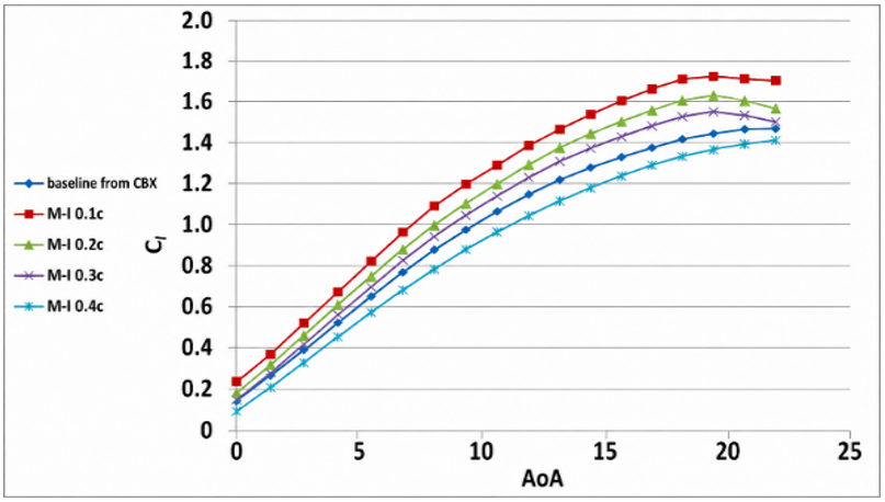
Figure 9 illustrates the relationship between the lift coefficient (CL) and angle of attack (α) for the optimization scheme of the morphed leading-edge concept. It can be observed that the slope of the lift curve (dCL/dα) improved owing to forward morphing.
Figure 9. Lift coefficient versus angle of attack for the baseline and leading-edge morphed NACA 2412 at different morphing positions (CBX results, θLE = 10°, Mach = 0.13, Re = 3.1 × 10⁶)
This enhancement may be explained by the fact that LEM causes an effective camber increase and circulation rise in the wing section. This leads to increased flow attachment and momentum exchange in the boundary layer, and hence, higher lift production.
These findings are in line with classical aerodynamic concepts and previous computational analyses, where it was found that LEM leads to increased circulation and delayed stall [12-14].
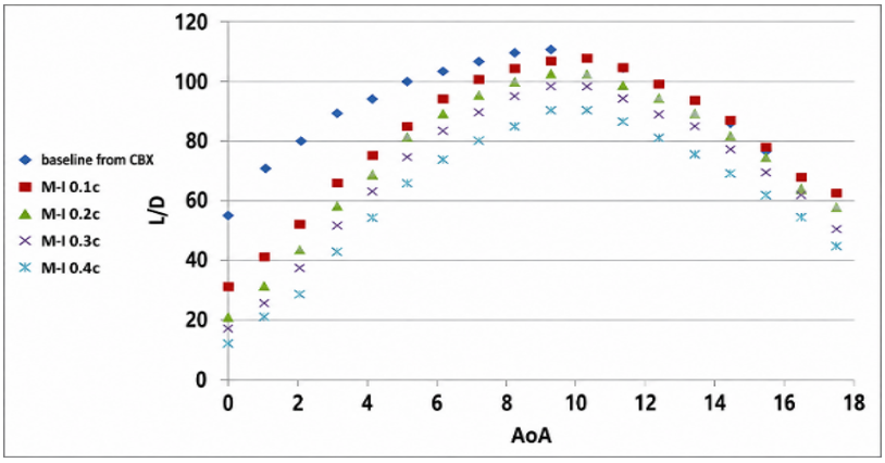
Figure 10 illustrates the influence of the LEM location (DLE) on the aerodynamic performance. From the analysis, it can be concluded that placing the morphing area around DLE ≈ 0.2 c provides the best balance between improved lift and decreased drag.
Figure 10. Lift-to-drag ratio versus angle of attack for the baseline and leading-edge morphed NACA 2412 at different morphing positions (CBX results, θLE = 10°, Mach = 0.13, Re = 3.1 × 10⁶)
When the morphing area is placed too close to the leading edge (x/c < 0.1), significant curving occurs, which increases the influence of viscosity and flow instability. However, when the morphing location was moved closer to the middle of the chord, the control of the suction peak decreased, making it less effective in preventing flow separation.
A preferable location of DLE ≈ 0.2 c ensures a more effective pressure distribution and avoids negative pressure gradients, in line with current research on adaptive airfoil optimization [7, 10, 11, 15].
Moving the morphing hinge downstream from 0.1 c to 0.4 c modifies the camber distribution as follows:
•forward morphing (0.1 c ≤ x ≤ 0.2 c) increases the lift slope
•mid-chord morphing increases the curvature; while raising the drag, morphing too far aft reduces the stall delay effect
The results indicate that DLE ≈ 0.2 c provides an optimal balance between lift augmentation and drag control.
3.1.4 Influence of trailing-edge morphing rotation angles (θLE)
Figure 11 shows the influence of the trailing-edge rotation angle (θTE) on the aerodynamic performance. The lift coefficient is significantly increased by θTE, which is mainly due to the presence of increased camber [29]; nevertheless, there is also an evident increase in drag, particularly at low α.
The main reason for this phenomenon can be attributed to the increased intensity of wake formation and pressure drag induced by large camber angles. Although the trailing-edge transformation allows increasing lift, it leads to additional energy loss within the wake owing to the higher negative pressure gradient.
Such phenomena correspond to the findings that trailing-edge deformation affects lift increase to a higher extent compared to separation control; hence, the optimization of trailing edge transformation is required [7, 10, 11].
Figure 11. Comparison of original baseline NACA 2412 airfoil and optimized morphing trailing-edge airfoil lift/drag ratios versus the angle of attack from CBX framework, at Mach = 0.13 and Re = 3,100,000
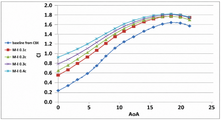
Figure 12. Aerodynamic performance lift coefficient with different deflection positions of the optimized morphing trailing edge of NACA 2412 airfoil at θTE = 10°, Mach = 0.13, and Re = 3,100,000
Figure 13. Aerodynamic performance lift coefficient with different deflection positions of the optimized morphing trailing edge of NACA 2412 airfoil at θTE = 10°, Mach = 0.13, and Re = 3,100,000
3.1.5 Influence of trailing-edge morphing location (DTE)
Figures 12 and 13 demonstrate how varying the location of the morphing trailing edge, DTE, affects both the lift coefficient and aerodynamic efficiency. Based on the analysis, the region where the most efficient operation can be achieved lies between 0.7 c and 0.8 c.
Placing the morphing region closer to the trailing edge (x/c > 0.85) implies that only minor changes can be made with respect to modifying the curve. However, placing the morphing region at a further distance means stronger negative pressure gradients, thereby affecting flow stability.
The aforementioned optimum region allows effective modification of the camber curve and pressure recovery behavior, as stated in the literature review [7, 10, 11, 15] on morphing airfoils.
3.1.6 Influence of CoMpLETE morphing rotation angles (θLE, θTE)
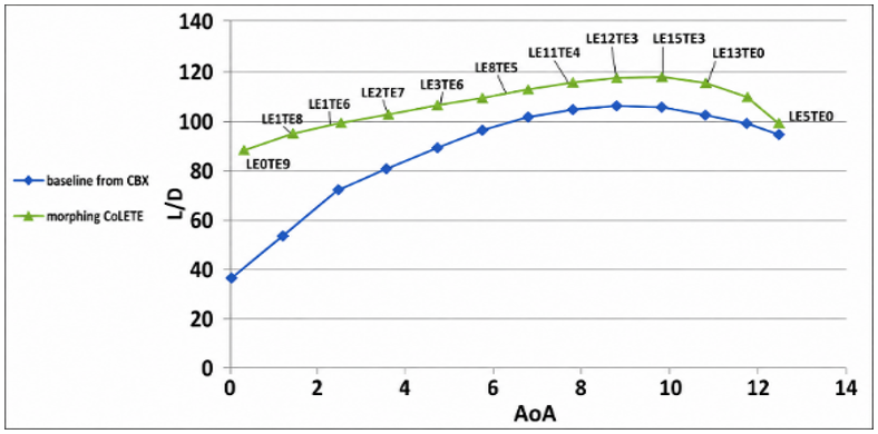
The influences of both morphing techniques in terms of the lift coefficient and lift/drag ratio are presented in Figures 14 and 15. As can be seen from the figures, it becomes obvious that the proposed CoMpLETE morphing technique outperforms the other morphing techniques.
Figure 14. Comparison of the lift coefficients of the original baseline NACA 2412 airfoil and the optimized CoMpLETE airfoil with respect to the angle of attack for both the CBX framework and ANSYS FLUENT, at Mach = 0.13 and Re = 3,100,000
Figure 15. Comparison of original baseline NACA 2412 airfoil and optimized CoMpLETE airfoil lift/drag ratios versus angle of attack from both CBX framework and ANSYS FLUENT, at Mach = 0.13 and Re = 3,100,000
This advantage stems from the synergy between the increase in the leading-edge suction and the trailing-edge camber effect. The combined shape change produces a favorable pressure distribution, lower pressure gradient, and better boundary layer stability, and the synergy between the two morphing regions is responsible for the stall delay, maximum lift coefficient increase, and aerodynamic efficiency. Similar synergies have been observed in other studies on combined morphing methods [15, 16].
The optimal morphing parameters obtained from the CBX optimization framework are listed in Table 4.
These values represent the configuration that maximizes the lift/drag ratio at an angle of attack of 10°, a Reynolds number of 2 × 10⁶, and a Mach number of 0.13.
The enhanced configuration has the following advantages:
•The value of CLmax is increased to 1.5386
•The stall angle is increased to 19°
•The maximum L/D is increased to 94.89
It is evident that the combined movement between the leading and trailing edges has significant aerodynamic benefits, which go beyond the effects that can be achieved through the change in the cambered shape alone. The difference between the values predicted by the CBX and RANS methods was still 2.2%, which proves the consistency between the results obtained using different methods with different degrees of complexity.
The observed benefits can be explained as follows:
•The pressure loading is redistributed along the chord
•The adverse pressure gradient is reduced
•The change in the rate of change in the cambered shape is regulated
Table 4. Optimal morphing design variables obtained using the CBX optimization framework
|
Parameter |
Symbol |
Optimal Value |
Description |
|
Leading-edge rotation angle |
θLE |
9.8° |
Rotation of morphing leading edge |
|
Trailing-edge rotation angle |
θTE |
11.2° |
Rotation of morphing trailing edge |
|
Leading-edge morphing location |
DLE |
0.21 c |
Distance from leading edge |
|
Trailing-edge morphing location |
DTE |
0.76 c |
Distance from leading edge |
3.1.7 Separate contributions of leading & trailing-edge morphing
To identify the individual role of each morphing region, the leading-edge only, trailing-edge only, and coordinated (CoMpLETE) configurations were compared against the baseline using the XFOIL-based CBX results, as summarized in Table 5. TEM was the main source of the lift gain: by increasing the aft camber and circulation, it raised the maximum lift coefficient from 1.673 to 1.721 and delayed stall by 3°. LEM acted differently; on its own, it slightly reduced the maximum lift coefficient (to 1.605) but delayed stall by 1° by reshaping the suction peak and reducing the leading-edge adverse pressure gradient, which stabilizes the flow rather than adding lift.
Table 5. Individual and combined contributions of CoMpLETE to the maximum CL and stall angle of the NACA 2412 airfoil (XFOIL screening results, Re = 3.1 × 10⁶, Mach = 0.13)
|
Configuration |
Cₗ,ₘₐₓ |
Stall Angle |
Δ Stall vs Baseline |
|
Baseline NACA 2412 |
1.673 |
17° |
— |
|
Leading-edge morphing only (LE-only) |
1.605 |
18° |
+1° |
|
Trailing-edge morphing only (TE-only) |
1.721 |
20° |
+3° |
|
Coordinated morphing (CoMpLETE) |
1.720 |
21° |
+4° |
When both regions morph together, their effects are not simply additive. The coordinated configuration achieved the largest stall delay (to 21°, a 4° increase over the baseline) while raising the maximum lift coefficient to 1.720. Because LEM alone lowers the maximum lift coefficient, the combined gain in lift exceeds the sum of the two individual contributions, indicating that the improvement originates mainly from the interaction between the two mechanisms: TEM supplies the additional loading, while LEM simultaneously relaxes the suction-peak pressure gradient and keeps the boundary layer attached, allowing the higher loading to be sustained to a larger angle of attack. This coupling explains why the CoMpLETE strategy outperforms either single-edge case.
3.1.8 Reynolds number sensitivity
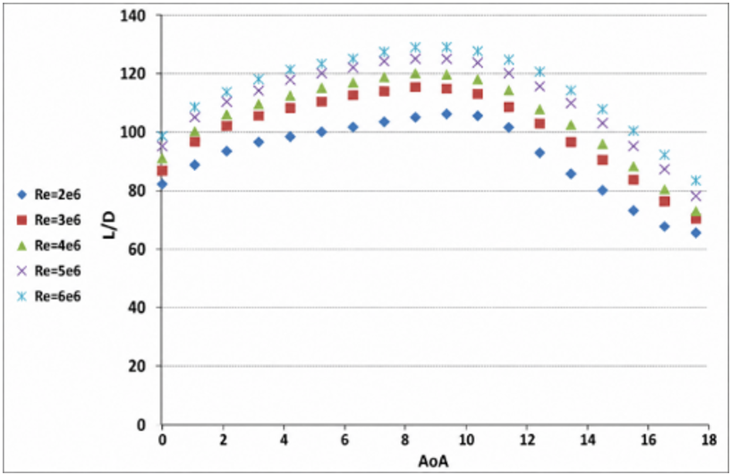
Figure 16 shows the influence of the Reynolds number on the aerodynamic behavior of the improved CoMpLETE. As the Reynolds number increased, the energy within the boundary layer increased, preventing early separation and enhancing lift production.
Figure 16. The effect of the Reynolds number on the lift/drag ratios of the optimized CoMpLETE NACA 2412 airfoils versus the angle of attack for the CBX framework at Mach = 0.13
Therefore, the optimum L/D was observed at a larger AoA due to better aerodynamic efficiency. A higher Reynolds number means smaller viscosity effects. Thus, the improvement of pressure recovery, which leads to a reduction in drag, can take place. The conclusions match well with known aerodynamics principles and modern research on morphing airfoils at different Reynolds numbers [5-7].
As can be seen from Figure 16, the airfoil's performance is dependent on the Reynolds number. Nevertheless, the aerodynamic superiority of coordinated morphing is valid for the studied range of Reynolds numbers, which varies from 2 × 10⁶ up to 6 × 10⁶. Specifically, the relative gain in L/D ratio is the largest at the smallest studied Reynolds number, where the boundary layer is likely to separate and therefore could benefit from suction peak control at LE, but at larger Reynolds numbers the baseline flow becomes more resistant, resulting in the gain decreasing only moderately. The optimized airfoil demonstrates the best aerodynamic performance among both designs, under all conditions of the studied range.
It should be mentioned that the presented data were obtained for the NACA 2412 airfoil, optimized at one design condition (AoA = 10°, Re = 3.1 × 10⁶, M = 0.13). So, the optimal lift coefficient of 1.5386 and lift/drag ratio improvement of more than 30% pertain to these conditions only. The quantitative data cannot be used for the different Reynolds numbers, Mach numbers, and geometries of airfoil wings. These results provide confirmation of the efficiency of the developed CBX technology of wing morphology control.
3.2 Flow-field analysis and stall mechanism
3.2.1 Velocity field characteristics
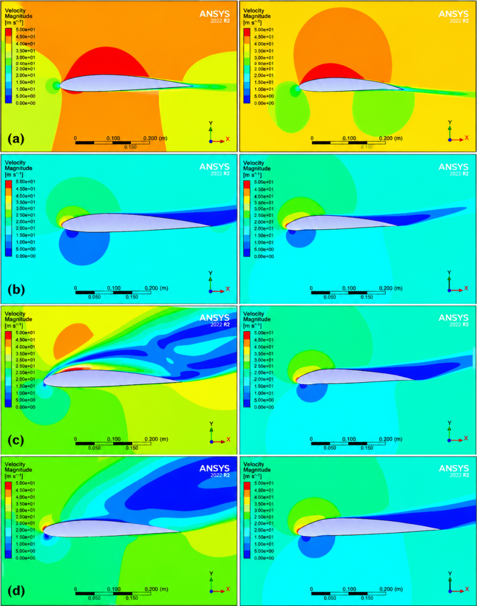
The velocity field contours in Figure 17 clearly illustrate the distinct aerodynamic behavior between the baseline and optimized morphing configurations across different angles of attack. Specifically, for a very low angle of attack (AoA = 0°), both configurations demonstrated flow attachment accompanied by a nearly constant velocity distribution. However, while the velocity contours appear quite uniform for the baseline configuration, a local acceleration appears in the area of the leading edge for the optimized morphing airfoil owing to the creation of a strong suction peak and thus a more favorable pressure gradient distribution. These conclusions correspond to the results obtained for morphing wing profiles, indicating the role of leading-edge deformations in improving the stability of the boundary layer under pre-stall conditions [12-14].
Figure 17. Velocity vectors for optimized morphing airfoil at a: AoA = 0°, b: AoA = 18°, c: AoA = 19° (stalling angle), d: AoA = 20°. (left column for the baseline airfoil and the right column for the morphing airfoil)
At higher angles of attack (AoA = 18°), the baseline airfoil demonstrated flow separation in the mid-chord region, characterized by decreased velocity and the presence of recirculation areas. In comparison, the optimized morphing profile exhibited a region of significantly higher velocity along the top surface, indicating later boundary layer separation. This result can be explained by morphing induced pressure redistribution, resulting in the delay of the separation process, which was confirmed by previous research on morphing airfoils [7, 10, 11, 15].
Finally, at AoA = 19°, which corresponds to stall, Figure 17 shows that the flow over the baseline airfoil experiences a significantly separated flow region starting from approximately x/c ≈ 0.6. In turn, for the optimized configuration, separation occurred at a further point on the chord; that is, there was evidence of a significant delay in stall occurrence. This effect is related to leading–trailing edge morphing, resulting in a reduction in the adverse pressure gradient and retention of a higher boundary-layer momentum [15, 16].
At AoA > 19°, when separation occurs for both configurations, the morphed airfoil demonstrates a lower level of recirculation behind the separation point and a higher velocity of the remaining flow, providing partial separation flow reattachment and thus better post-stall performance. The advantageous features of morphing airfoils have been discussed in recent studies [5, 7, 16].
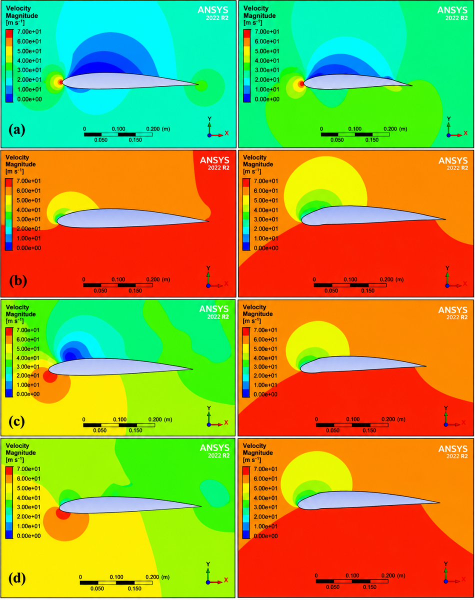
These effects can be correlated with the pressure distribution shown in Figure 18, confirming that the improvement in pressure recovery is a consequence of delayed separation. In summary, the enhanced aerodynamic performance in the optimized configuration was a consequence of its improved flow control capabilities.
3.2.2 Pressure field characteristics
As shown in Figure 18, the contours of the pressure coefficient clearly demonstrate the high effectiveness of the CoMpLETE morphing concept for optimizing the pressure distribution on the airfoil surface. Specifically, at AoA = 0°, both configurations showed approximately symmetric pressure distributions; however, the optimized configuration showed some enhancement in the suction strength in the proximity of the leading edge, which corresponded to an increased acceleration of the air stream and improved pressure gradient. These observations are consistent with recent research on the morphing effects on the leading edge of airfoils, demonstrating that morphing increases the strength of the suction peak and improves the stability of the boundary layers [12-14].
At AoA = 18°, from Figure 18, it is evident that, unlike in the optimized configuration, for the baseline airfoil, the appearance of a pressure plateau begins at approximately x/c ≈ 0.6. This feature is indicative of flow separation caused by the formation of an adverse pressure gradient. Similar trends were observed during the investigation of morphed airfoils, demonstrating the effect of combined morphing on the redistribution of pressure and postponement of the onset of flow separation [10, 11, 15].
During stall onset (AoA = 19°), rapid pressure flattening was observed over a large part of the chord for the baseline airfoil, indicating full separation of the boundary layer. However, for the optimized configuration, the pressure variations were less sharp and corresponded to partial flow attachment. This is explained by the synergistic effect of morphing at both the leading and trailing edges, allowing the adverse pressure gradient to remain lower and the momentum to remain higher in the boundary layer [15, 16].
For AoA = 20°, whereas for the baseline configuration, the pressure distribution becomes very irregular owing to the separation of flow, a more uniform behavior is evident for the optimized airfoil. As in other contemporary studies on morphed airfoils, such results suggest better aerodynamic stability of the configuration in the post-stall range owing to improved pressure recovery and lower intensity of separation [5, 7, 16]. These results are further supported by Figure 17, which shows the velocity fields, proving the direct connection between the separation delay and improved pressure distribution.
Figure 18. Pressure coefficient (Cp) contours around the optimized CoMpLETE morphing airfoil at different angles of attack: (a) AoA = 0°, (b) AoA = 18°, (c) AoA = 19° (stall onset), and (d) AoA = 20°. (left column for the baseline airfoil and the right column for the morphing airfoil)
3.2.3 Streamline topology
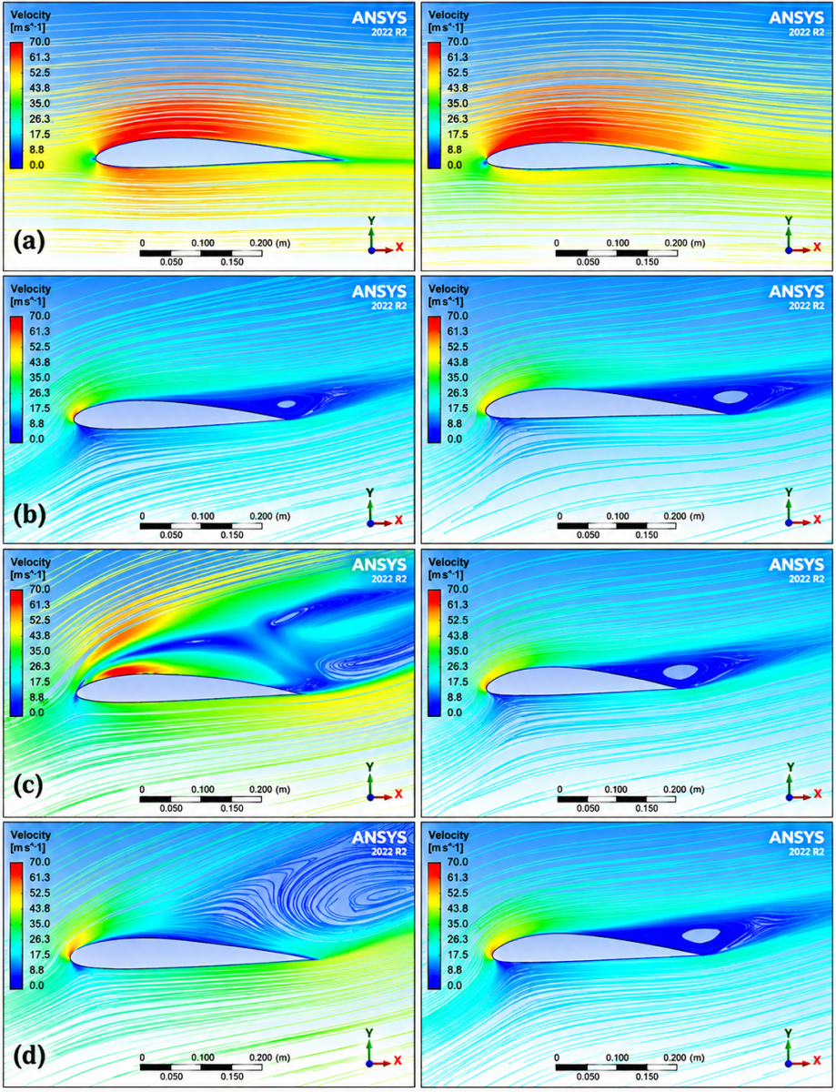
The streamline topology shown in Figure 19 provides additional evidence of the aerodynamic advantages offered by the improved CoMpLETE morphing design. Under low angles of attack, the streamlined pattern was smooth and completely attached for both designs; however, the streamlined curve in the optimized design was sharper and closer to the leading edge, indicating a higher circulation intensity and better lift production. The results match those of previous studies, revealing that LEM accelerates airflow and intensifies circulation before stall [12-14].
In contrast, for AoA = 18°, the baseline airfoil shows streamline detachment and vortex creation in the mid-chord part owing to boundary layer separation caused by the adverse pressure gradient. Meanwhile, the optimized design features much better flow attachment on the top surface, delayed vortex formation, and greater resistance to boundary layer separation. This finding is consistent with the results of modern studies on morphing airfoils [10, 11, 15].
At AoA = 19°, which signifies the stall point, the baseline geometry exhibits flow separation, characterized by the chaotic nature of the streamlines and strong vortices. The optimized geometry, on the other hand, exhibited a delayed formation of vortices and an ordered topology of the streamlines, signifying flow reattachment and a considerable delay in the occurrence of stall. This is due to the combined effect of leading & trailing-edge morphing, which alters the pressure distribution and maintains the boundary layer momentum [15, 16].
Finally, at AoA = 20°, both configurations are characterized by separated flow, yet the optimized airfoil demonstrates lower vortex size and better streamline organization. This indicates that there is more flow attachment for the optimized configuration, indicating improved stall resistance. Similar effects were recently found in other morphing airfoils with higher angles of attack [5, 7, 16].
Thus, these results support previous conclusions drawn from the streamline topology, which shows that the optimization of flow attachment and delay in separation occur owing to enhanced flow control. In general, it was proven that CoMpLETE morphing significantly contributes to flow attachment improvement, decreased vortex intensity, and stall resistance improvement.
Figure 19. Stream Line for optimized morphing airfoil at a: AoA = 0°, b: AoA = 18°, c: AoA = 19° (stalling angle), d: AoA = 20°. (left column for the baseline airfoil and the right column for the morphing airfoil)
The deformation of the leading/trailing edges affects the global distribution of circulation, thus enhancing lift.
3.3 Quantitative aerodynamic comparison
To provide a quantitative idea of the aerodynamic improvement provided by the CoMpLETE morphing technique, a comparison between the original and optimized airfoils is presented in Table 6.
The results indicate that the aerodynamic improvement achieved using the CoMpLETE morphing technique includes more than just the enhancement of the maximum lift coefficient (CLmax). Other improvements involve delaying the onset of flow separation.
Table 6. Quantitative aerodynamic comparison (high-fidelity $\gamma-{Re}_\theta$ SST RANS validation at Re = 3,100,000, Mach = 0.13)
|
Parameter |
Baseline |
CoMpLETE |
Improvement |
|
CL,max |
1.21 |
1.5386 |
+27.1% |
|
Stall angle |
16° |
19° |
+18.7% |
|
Maximum L/D |
72.4 |
94.89 |
+31.1% |
|
Separation onset (x/c) |
0.62 |
0.78 |
+0.16 c |
3.4 Pressure coefficient (Cp) distribution analysis
To gain insight into the underlying aerodynamics, the pressure coefficient distributions for the original and optimized airfoils at AoA = 10°, 18°, and 19° are presented in Figure 20.
Figure 20. Pressure coefficient distributions of the baseline and optimized CoMpLETE airfoils at selected angles of attack (AoA = 10°, 18°, and 19°)
For the optimized airfoil at AoA = 10°:
•A higher suction peak at x/c ≈ 0.05
•A smoother pressure recovery
At AoA = 18°, the baseline airfoil shows pressure plateau formation starting at x/c ≈ 0.6, which is indicative of separation onset, whereas the CoMpLETE configuration maintains pressure recovery up to x/c ≈ 0.78.
At AoA = 19°, the baseline configuration experienced abrupt pressure flattening, whereas the optimized airfoil preserved partial attachment, explaining the extended stall angle.
This mechanism is consistent with the findings of Aziz et al. [21] and Bashir et al. [22], who proved that the deformation of the leading/trailing edges suppresses the adverse pressure gradient.
3.5 Sensitivity ranking of morphing parameters
In the present study, the sensitivity analysis was carried out by computing the relative change in the highest L/D achieved owing to the variation of each design parameter individually. The sensitivity of each of the design parameters with respect to the aerodynamic performance is shown in Table 7.
Table 7. Sensitivity ranking of design parameters
|
Parameter |
Relative Impact on L/D |
Rank |
|
θLE |
High |
1 |
|
θTE |
Moderate–High |
2 |
|
DLE |
Moderate |
3 |
|
DTE |
Low–Moderate |
4 |
From the above-mentioned results, it can be clearly seen that the rotation of the leading edge is the most dominant parameter in relation to the postponement of stall and increase in efficiency. Such observations are consistent with the research studies concerning droop nose [7, 17].
3.6 Optimization convergence and computational efficiency
The optimization convergence of the proposed BWO algorithm is illustrated in Figure 21, where it can be observed that the optimization process converges rapidly in the initial 20 iterations and before the 45th iteration. The acceleration of the optimization convergence is attributed to the elimination mechanism based on cannibalism, which improves the optimization efficiency and maintains diversity. The optimization pattern was consistent with aerodynamic optimization studies using the BWO algorithm [18].
Figure 21. Convergence history of the Black Widow Optimization (BWO) optimization algorithm
The convergence behavior observed in this study is consistent with previously reported comparisons between the BWO algorithm and other metaheuristic optimization methods, such as GA and PSO, reported in the literature [17, 18].
3.7 Comparison with existing morphing airfoil studies
The observed aerodynamic benefits of the optimized CoMpLETE configuration were consistent with the results of previous investigations on morphing airfoils reported in the literature. For example, Bashir et al. [17, 18] observed lift enhancements of 15% to 20% for droop-nose type morphing configurations. Aziz et al. [21] also observed stall extension of 2° to 3° for combined leading/trailing edge deformations. Similarly, Zhang et al. [10] reported gradient-based optimization for morphing airfoils and observed the benefits of adaptive cambered modifications for improving the aerodynamic performance.
A comparison of the current study with previous investigations on morphing airfoils indicates that the current study achieved consistent aerodynamic benefits using a single Python-based optimization environment that combined CST, BWO, and XFOIL. The current results are consistent with previous investigations and demonstrate the benefits of combined morphing deformations for improving flow separation and aerodynamic performance.
3.8 Aerodynamic stability and drag polar analysis
The aerodynamic stability characteristics of the optimized CoMpLETE configuration were analyzed using the pitching-moment coefficient (Cm) about the quarter-chord reference point. The variation in the pitching moment coefficient with the angle of attack (AoA) for the baseline and optimized configurations is shown in Figure 22(a). The baseline NACA 2412 configuration showed an almost linear variation in the pitching-moment coefficient up to stall, which is typical for a mildly cambered airfoil before stall. The optimized CoMpLETE configuration exhibited a moderate negative moment increment owing to the increased camber.
Figure 22. Aerodynamic characteristics of baseline and optimized CoMpLETE NACA 2412 airfoils: (a) pitching moment coefficient (Cm) versus angle of attack (AoA), and (b) drag polar (CL versus CD) at Re = 3.1 × 10⁶ and Mach = 0.13
In the pre-stall region (AoA < 15°), the slope of Cm remained stable, indicating preserved longitudinal stability. Near the stall region (AoA ≈ 18°–19°), the optimized configuration shows a smoother Cm transition, whereas the baseline configuration exhibits a more abrupt variation associated with flow separation. The absence of an abrupt change in the pitching moment coefficient indicates that the morphing configuration did not introduce destabilizing aerodynamic effects. Previous research on combined morphing airfoils has revealed analogous tendencies [21, 22].
A comparison of the drag polars between the baseline and optimized configurations is shown in Figure 22(b). The optimized CoMpLETE configuration demonstrated an upward shift in the polar curve, an expanded linear lift region, and a delayed onset of drag divergence. For a lift coefficient close to CL ≈ 1.2, the optimized configuration showed a decrease in the drag coefficient (CD) by approximately 12% compared to the baseline configuration. A smoother polar plot represents improved boundary layer characteristics and reduced pressure drag. These results are consistent with those of previous studies on adaptive camber morphing airfoils by Gabor et al. [6] and Zhang et al. [10].
3.9 Flow topology metric: integrated vorticity magnitude
To quantify the separation intensity and wake development, the integrated vorticity magnitude over the computational domain was evaluated as follows:
$\Omega_{ {int }}=\int_{\Omega}|\omega| d A$ (10)
where, ω represents the local vorticity magnitude.
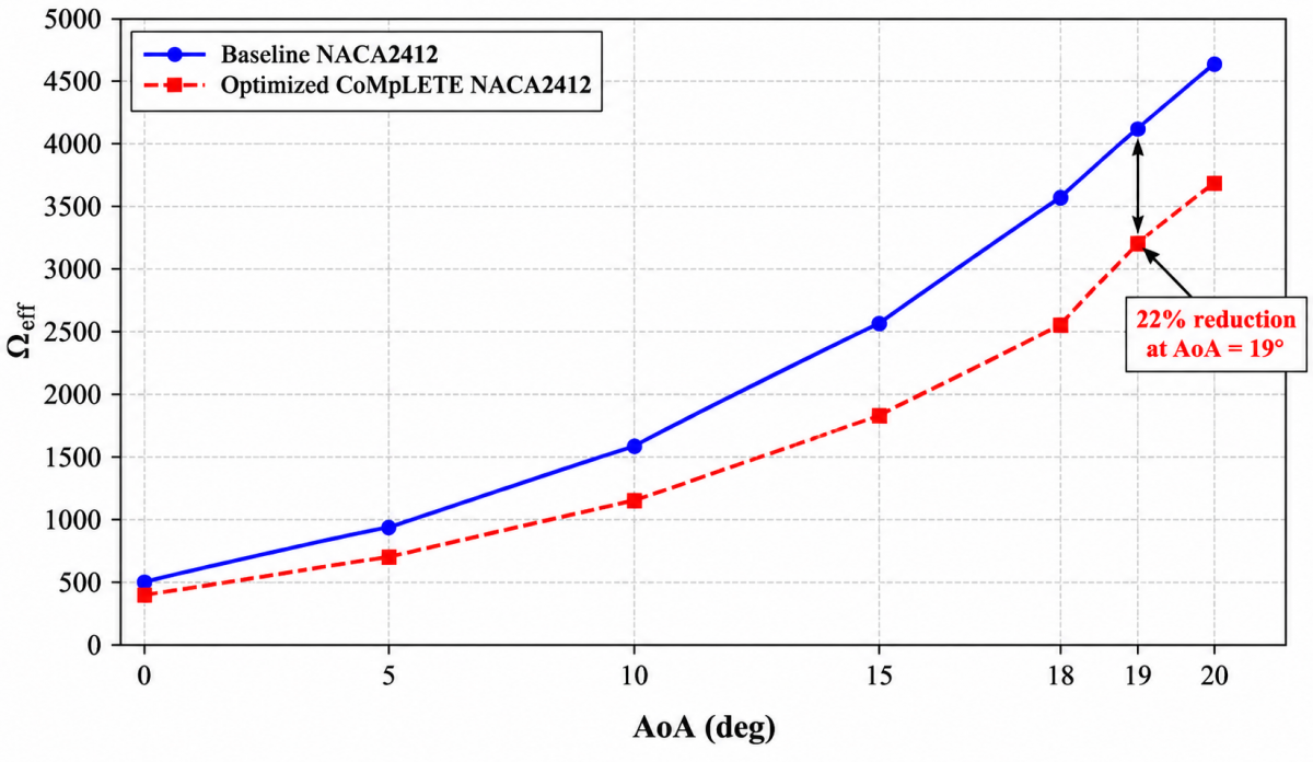
The dependence of the integrated vorticity Ωint on the angle of attack (AoA) is shown in Figure 23. It can be seen that the results indicate:
•Similar levels of vorticity at low AoA values (≤10°)
•Significant differences for AoA > 15°
•For AoA = 19°, the integrated vorticity magnitude of the baseline configuration is 22% higher compared to the value of the CoMpLETE configuration
This reduction indicates that
•Suppression of large-scale separation structures
•Reduction of wake widths
•Improved flow attachment
Quantification of the reduction in separation using the vorticity-based metric serves as an objective measure of the effectiveness of suppression. This supports the results obtained using the streamline and pressure contour plots presented in Figures 17–19. A similar quantification of the flow topology was used to study transient morphing simulations by Bashir et al. [22], demonstrating the importance of vortex structure control in stall delay mechanisms.
Figure 23. Variation of integrated vorticity magnitude (Ωint) with angle of attack for baseline NACA 2412 and optimized CoMpLETE NACA 2412 configurations at Re = 3.1 × 10⁶ and Mach = 0.13
3.10 Integrated discussion of aerodynamic mechanism
The improvements of the optimized configuration can be attributed to the leading-edge and TEM techniques used in this case. The LEM deforms the location of the pressure peak of suction, while the TEM modifies the camber, hence promoting pressure recovery, delaying separation, and increasing lift/drag ratio. The same effects have been observed for the morphing airfoils where the camber variations had considerable influence on adverse pressure gradients and stall onset [21, 22].
The optimized configuration displays significant improvement in the pressure-coefficient distribution (Figure 20), characterized by a more pronounced suction peak and gradual change of pressure from front to rear. The pressure-distribution analysis proves to be a reliable tool in studying the airfoil separation phenomenon, with slow pressure recovery and small pressure gradients promoting boundary layer stabilization [30, 31].
Visualizations of the flow patterns (Figures 17–19) suggest successful separation-bubble suppression, achieved through the formation of separation bubbles later and decreasing the size of the large vortices formed during flow. The same results have been obtained in the research concerning morphing airfoils [32].
The analysis of integrated vorticity magnitude conducted in Section 3.9 suggests that the optimized configuration shows a 22% decrease in the magnitude at AoA = 19°. It indicates that the optimized combined morphing successfully influences control of major vortices and stall onset. Similar results have been obtained previously for the adaptive camber morphing control, where it was shown that such a kind of morphing helps to decrease flow separation strength [6, 10].
The evaluation of the pitching moment and pitching coefficient allows us to state that the optimized configuration demonstrates good aerodynamic stability: moderate negative pitching moment increase without abrupt stall region changes. Such effect also corresponds to the results of camber distribution variation research [21, 22].
As seen from Figure 22(b), the shift of drag polars shows improvement in aerodynamic efficiency: smaller drag at moderate lift values, achieved due to better boundary-layer performance and less pressure drag. Thus, this result corresponds to other camber morphing optimization examples discussed before [6, 10].
With respect to the optimization convergence aspect, the use of BWO shows consistent performance: fast initial convergence followed by gradual optimization up to the optimum solution, like many other nature-inspired aerodynamic optimizations [17, 18].
A multi-fidelity optimization approach allows for significantly increased efficiency of optimization, balancing the accuracy of results and computational cost. It is extensively used in aerospace engineering design [23, 24].
In conclusion, the morphing wing concept provides considerable advantages thanks to the synergism between leading & trailing-edge morphing, promoting pressure recovery, separation strength reduction, and increased lift/drag ratio [34].
In this study, through the integration of the moment analysis, the understanding of the drag polars, and the quantification of the vortices, it has been demonstrated that the aerodynamic enhancement of the CoMpLETE configuration can be attributed to the following three synergistic mechanisms:
•Leading-edge suction stabilization
•Redistribution of pressure recovery along the chord
•Suppression of large-scale separation vortices
While the effect of the trailing edge morphing, in isolation, is to increase the lift, the effect of the combined morphing is to alter the distribution of the pressure gradients as well as the topology of the wake. The nonlinear aerodynamic coupling of θLE and θTE has resulted in a synergistic effect, enhancing the performance beyond the sum of the individual effects of each morphing.
Beyond these aerodynamic mechanisms, it is important to consider the engineering implications of the optimized configuration. The deflections and morphed shapes obtained here represent target aerodynamic geometries rather than a specific mechanical realization. Achieving them in practice would require a compliant morphing skin together with an internal actuation system [33]. For example, distributed smart-material actuators or compliant mechanisms capable of producing the required leading & trailing edge deflections while sustaining the associated surface strain. The geometric arc-length, curvature, and volume constraints applied in this study were introduced precisely to keep the deformations within a physically plausible envelope for such skins (surface strain below the 1–3% range), but the present work does not model the actuators, the internal structure, or the associated actuation power and structural complexity. These practical aspects actuator selection and sizing, structural load-bearing capacity, and the manufacturability of the deformable skin are beyond the scope of the current purely numerical study and are left as important directions for future work, in which the aerodynamic targets identified here would be coupled with detailed aero-structural and actuation models and validated experimentally.
This study proposes a Python-based framework for optimizing combined morphing airfoils with both LE and TE morphing using a multi-fidelity aerodynamic optimization approach. The framework combines CST geometry parametrization, BWO, and automated XFOIL coupling to efficiently explore the CoMpLETE morphing airfoil design space. The CST parameterization and BWO optimization effectively analyzed the CoMpLETE morphing airfoil design space. The optimized morphing airfoil configuration showed significant aerodynamic benefits over the baseline airfoil: a maximum lift coefficient of 1.5386 and a stall angle of 19°, signifying a stall-delay improvement of 18–20%. XFOIL and γ-Rɛθ SST RANS simulations consistently indicated these benefits with a difference of less than 2.2%. The flow field analysis indicates that these benefits arise from changes in the pressure fields and wakes: LE morphing stabilizes the suction peaks and delays stall, whereas TE morphing adjusts the camber to reduce adverse gradients. The total vorticity magnitude near the stall showed a potential 22% reduction in the separation intensities. The drag polar shifts and pitching-moment changes indicated no destabilizing aerodynamics from stall-delay phenomena. Sensitivity analysis showed that LE rotation mainly affects stall resilience, whereas TE deflection mainly increases lift coefficients. Their combined nonlinear interactions provide benefits beyond individual contributions. The XFOIL coupling in the optimization results in a reduction in the CFD iterations by ~85% while maintaining accuracy in separation-dominated flow regimes. The BWO optimization converged consistently with low stochastic variation in the results.
Although this study provides valuable insights into the optimization of morphing airfoils using a multi-fidelity aerodynamic optimization approach, it is limited to the two-dimensional steady RANS method and excludes three-dimensional effects, aeroelastic effects, and morphing skin actuation. Furthermore, this study optimizes only a single flight condition, which might not represent the multi-point reality of flight conditions. Future studies should include 3D cases, aeroelastic phenomena, and unsteady cases for real-life scaling.
This study provides a physically consistent and computationally efficient framework for morphing airfoil optimization using the CST-BWO multifidelity aerodynamic optimization approach for next generation morphing wings. The CBX framework provides a practical solution for morphing airfoil optimization using a multi-fidelity aerodynamic optimization approach for morphing airfoils and adaptive wings.
It should be emphasized that the present results establish the numerical feasibility of the coordinated leading & trailing-edge morphing strategy rather than its readiness for practical implementation. The study is based on two-dimensional, steady RANS simulations and does not include structural deformation analysis, actuator or compliant-mechanism modeling, or experimental validation; the geometric arc-length, curvature, and volume constraints were used only as a proxy for structural feasibility. Consequently, the reported aerodynamic gains should be regarded as an upper bound achievable under idealized geometric morphing. Extending these findings toward practical morphing-wing design will require three-dimensional and unsteady analyses, coupled aero-structural modeling of the deformable skin and its actuation, and wind-tunnel validation. These aspects are identified as the natural next steps of this work.
|
A |
cross-sectional area |
|
Aₚ |
projected frontal area of vortex generator |
|
Dₕ |
hydraulic diameter |
|
f |
friction factor |
|
h |
convective heat transfer coefficient |
|
k |
thermal conductivity |
|
L |
channel length |
|
N |
number of vortex generator edges |
|
Nu |
Nusselt number |
|
P |
perimeter of vortex generator cross-section |
|
PEC |
performance evaluation criterion |
|
Re |
Reynolds number |
|
Sgen |
entropy generation |
|
T |
temperature |
|
u |
velocity magnitude |
|
Greek symbols |
|
|
α |
vortex generator attack angle |
|
θ |
mean field synergy angle |
|
μ |
dynamic viscosity |
|
ρ |
fluid density |
|
ω |
vorticity magnitude |
|
Subscripts |
|
|
h |
hydraulic |
|
gen |
generation |
|
max |
maximum value |
|
f |
fluid property |
|
th |
thermal enhancement component |
[1] Kan, Z., Li, D.C., Shen, T., Xiang, J.W., Zhang, L. (2020). Aerodynamic characteristics of morphing wing with flexible leading-edge. Chinese Journal of Aeronautics, 33(10): 2610-2619. https://doi.org/10.1016/j.cja.2020.03.012
[2] Wen, C.Y., Dai, Y.T., Xu, Y.T., Yang, C. (2024). Aerodynamic characteristics of a pitching airfoil with leading-edge morphing. Chinese Journal of Aeronautics, 37(7): 81-92. https://doi.org/10.1016/j.cja.2024.03.036
[3] Pecora, R. (2021). Morphing wing flaps for large civil aircraft: Evolution of a smart technology across the Clean Sky program. Chinese Journal of Aeronautics, 34(7): 13-28. https://doi.org/10.1016/j.cja.2020.08.004
[4] Thill, C., Etches, J., Bond, I., Potter, K., Weaver, P. (2008). Morphing skins. The Aeronautical Journal, 112(1129): 117-139. https://doi.org/10.1017/S0001924000002062
[5] Clements, D., Djidjeli, K. (2023). Aerodynamic performance of morphing and periodic trailing-edge morphing airfoils in ground effect. Journal of Aerospace Engineering, 36(3): 04023007. https://doi.org/10.1061/JAEEEZ.ASENG-4707
[6] Gabor, O.S., Simon, A., Koreanschi, A., Botez, R.M. (2016). Aerodynamic performance improvement of the UAS-S4 Éhecatl morphing airfoil using novel optimization techniques. Proceedings of the Institution of Mechanical Engineers, Part G: Journal of Aerospace Engineering, 230(7): 1164-1180. https://doi.org/10.1177/0954410015605548
[7] Themistokleous, C., Markatos, N.G., Prospathopoulos, J., Riziotis, V., Sieros, G., Papadakis, G. (2021). High-lift optimization methodology for the design of morphing leading and trailing edges on morphing wings. Applied Sciences, 11(6): 2822. https://doi.org/10.3390/app11062822
[8] Burnazzi, M., Radespiel, R. (2014). Design and analysis of a droop nose for Coanda flap applications. Journal of Aircraft, 51(5): 1567-1579. https://doi.org/10.2514/1.C032434
[9] Bashir, M., Longtin-Martel, S., Botez, R.M., Wong, T. (2021). Aerodynamic design optimization of a morphing leading edge and trailing edge airfoil–Application on the UAS-S45. Applied Sciences, 11(4): 1664. https://doi.org/10.3390/app11041664
[10] Zhang, Z.K., De Gaspari, A., Ricci, S., Song, C., Yang, C. (2021). Gradient-based aerodynamic optimization of an airfoil with morphing leading and trailing edges. Applied Sciences, 11(4): 1929. https://doi.org/10.3390/app11041929
[11] Kulfan, B.M. (2008). Universal parametric geometry representation method. Journal of Aircraft, 45(1): 142-158. https://doi.org/10.2514/1.29958
[12] Abbas, A.S., Mohammed, A.A. (2026). Multi-objective optimization and surrogate modeling of composite morphing airfoils: Trends, bottlenecks, and research priorities. Revue des Composites et des Matériaux Avancés - Journal of Composite and Advanced Materials, 36(2): 395-406. https://doi.org/10.18280/rcma.360215
[13] Ladson, C.L. (1988). Effects of independent variation of Mach and Reynolds numbers on the low-speed aerodynamic characteristics of the NACA 0012 airfoil section. NASA Technical Memorandum, 4074. https://ntrs.nasa.gov/citations/19880019495.
[14] Cheng, Y.W., Zeng, J.Y., Chen, Q., Liang, H.Z., Bai, P. (2022). Aerodynamic characteristics of morphing supercritical airfoils for aircraft with all-stage high performance. Applied Sciences, 12(3): 1128. https://doi.org/10.3390/app12031128
[15] ANSYS Inc. (2024). ANSYS Meshing User's Guide. ANSYS Inc., Canonsburg, PA. https://ansyshelp.ansys.com/public/Views/Secured/corp/v242/en/wb_msh/msh_book_wb.html.
[16] Hayyolalam, V., Pourhaji Kazem, A.A. (2020). Black Widow Optimization algorithm: A novel meta-heuristic approach for solving engineering optimization problems. Engineering Applications of Artificial Intelligence, 87: 103249. https://doi.org/10.1016/j.engappai.2019.103249
[17] Bashir, M., Longtin-Martel, S., Botez, R.M., Wong, T. (2022). Optimization and design of a flexible droop-nose leading-edge morphing wing based on a novel Black Widow Optimization algorithm—Part I. Designs, 6(1): 10. https://doi.org/10.3390/designs6010010
[18] Bashir, M., Longtin-Martel, S., Zonzini, N., Botez, R.M., Ceruti, A., Wong, T. (2022). Optimization and design of a flexible droop nose leading edge morphing wing based on a novel Black Widow Optimization (B.W.O.) algorithm—Part II. Designs, 6(6): 102. https://doi.org/10.3390/designs6060102
[19] Koreanschi, A., Gabor, O.S., Acotto, J., et al. (2017). Optimization and design of an aircraft's morphing wing-tip demonstrator for drag reduction at low speed, Part I – Aerodynamic optimization using genetic, bee colony and gradient descent algorithms. Chinese Journal of Aeronautics, 30(1): 149-163. https://doi.org/10.1016/j.cja.2016.12.013
[20] Negahban, M.H., Bashir, M., Traisnel, V., Botez, R.M. (2024). Seamless morphing trailing edge flaps for UAS-S45 using high-fidelity aerodynamic optimization. Chinese Journal of Aeronautics, 37(2): 12-29. https://doi.org/10.1016/j.cja.2023.10.024
[21] Aziz, M.A., Mansour, M., Iskander, D., Hany, A. (2019). Combined droop nose and trailing-edge morphing effects on airfoil aerodynamics. SN Applied Sciences, 1: 1033. https://doi.org/10.1007/s42452-019-0796-6
[22] Bashir, M., Negahban, M.H., Botez, R.M., Wong, T. (2024). Numerical simulation of the transient flow around the combined morphing leading-edge and trailing-edge airfoil. Biomimetics, 9(2): 109. https://doi.org/10.3390/biomimetics9020109
[23] Forrester, A.I.J., Keane, A.J. (2009). Recent advances in surrogate-based optimization. Progress in Aerospace Sciences, 45(1-3): 50-79. https://doi.org/10.1016/j.paerosci.2008.11.001
[24] Peherstorfer, B., Willcox, K., Gunzburger, M. (2018). Survey of multifidelity methods in uncertainty propagation, inference, and optimization. SIAM Review, 60(3): 550-591. https://doi.org/10.1137/16M1082469
[25] Morgado, J., Vizinho, R., Silvestre, M.A.R., Páscoa, J.C. (2016). XFOIL vs CFD performance predictions for high lift low Reynolds number airfoils. Aerospace Science and Technology, 52: 207-214. https://doi.org/10.1016/j.ast.2016.02.031
[26] Menter, F.R., Langtry, R.B., Likki, S.R., Suzen, Y.B., Huang, P.G., Völker, S. (2006). A correlation-based transition model using local variables—Part I: Model formulation. Journal of Turbomachinery, 128(3): 413-422. https://doi.org/10.1115/1.2184352
[27] Langtry, R.B., Menter, F.R. (2009). Correlation-based transition modeling for unstructured parallelized computational fluid dynamics codes. AIAA Journal, 47(12): 2894-2906. https://doi.org/10.2514/1.42362
[28] Abbas, A.S., Mohammed, A.A. (2023). Improvement of plate-fin heat exchanger performance with assistance of various types of vortex generator. CFD Letters, 15(7): 131-147. https://doi.org/10.37934/cfdl.15.7.131147
[29] Majid, T., Jo, B.W. (2021). Comparative aerodynamic performance analysis of camber morphing and conventional airfoils. Applied Sciences, 11(22): 10663. https://doi.org/10.3390/app112210663
[30] Drela, M., Giles, M.B. (1987). Viscous-inviscid analysis of transonic and low Reynolds number airfoils. AIAA Journal, 25(10): 1347-1355. https://doi.org/10.2514/3.9789
[31] Abdessemed, C., Yao, Y.F., Bouferrouk, A. (2021). Near stall unsteady flow responses to morphing flap deflections. Fluids, 6(5): 180. https://doi.org/10.3390/fluids6050180
[32] Koreanschi, A., Gabor, O.S., Acotto, J., et al. (2017). Optimization and design of an aircraft's morphing wing-tip demonstrator for drag reduction at low speeds, Part II - Experimental validation using Infra-Red transition measurement from Wind Tunnel tests. Chinese Journal of Aeronautics, 30(1): 164-174. https://doi.org/10.1016/j.cja.2016.12.018
[33] Barbarino, S., Bilgen, O., Ajaj, R.M., Friswell, M.I., Inman, D.J. (2011). A review of morphing aircraft. Journal of Intelligent Material Systems and Structures, 22(9): 823-877. https://doi.org/10.1177/1045389X11414084
[34] Abbas, A.S., Mohammed, A.A. (2025). Experimental evaluation of morphing wing technologies: A systematic review. Revue des Composites et des Matériaux Avancés - Journal of Composite and Advanced Materials, 35(6): 1199-1209. https://doi.org/10.18280/rcma.350619