Zainab Rifaat Mohammed | Afrah Turki Awad* | Ganiyu Olabode Ajisegiri
© 2026 The authors. This article is published by IIETA and is licensed under the CC BY 4.0 license (http://creativecommons.org/licenses/by/4.0/).
OPEN ACCESS
Previous studies on phase change material (PCM)-based solar thermal energy storage systems have mainly focused on PCM selection, heat-transfer enhancement techniques, and structural modifications, whereas the influence of PCM mass as a practical system-sizing parameter has received comparatively limited attention. Therefore, this study experimentally investigates the effects of three paraffin wax masses, namely 10, 20, and 30 kg, on the thermal storage capacity, heat retention, and discharge behavior of a parabolic trough collector (PTC)-based thermal energy storage system under the outdoor climatic conditions of Kirkuk, Iraq. The selected masses represented approximately one-third, two-thirds, and the full nominal PCM capacity of the storage unit, respectively, while the PCM type, storage-tank geometry, double-helical-coil configuration, and operating conditions were maintained unchanged. A three-dimensional transient computational fluid dynamics (CFD) model based on the enthalpy–porosity method was additionally developed and validated for the 30 kg case to explain the dominant heat-transfer and phase-change mechanisms. The results showed that increasing PCM mass increased the stored thermal energy and prolonged the heat-discharge period. The theoretical stored energy increased from 2782 kJ for 10 kg of PCM to 8094 kJ for 30 kg of PCM, while the thermal energy recovery ratio increased from approximately 41.7% to 66.8%. The PCM storage unit under the 30 kg case kept useful hot-water availability for up to 8 h post sunset, relative to about 2 h in the system without PCM. These results show that PCM mass is a key design parameter that must be optimized based on the desired storage capacity, thermal response and period of discharge, as well as post-sunset hot-water utilization.
charging/discharging, computational fluid dynamics, heat retention, parabolic trough collector, phase change material, thermal energy recovery, thermal energy storage
Parabolic trough collector (PTC) produces valuable solar thermal energy, but their output directly depends on solar irradiation conditions and is non-existent after sunset [1, 2]. Furthermore, most of the research has focused on dispersing nanoparticles into the base fluid in order to improve the thermal efficiency of solar collectors [3-7]. Another improvement is the integration of the storage system within PTC systems, enabling collected heat to be stored in both sensible and latent forms (using the phase change material (PCM)) to power the system when solar input is low [8]. For instance, Awad et al. [9] dealt with improving the thermal energy storage performance of a molten-salt blend based on binary PCM embedded with CuO nanoparticles via an in-situ synthesis process. The results showed that 1 wt.% CuO-PCM resulted in more enhanced thermal storage capacity by 24.87%.
Raja et al. [10] integrated paraffin-based thermal energy storage with PTC to develop a heat storage system that can be efficiently used to supply domestic hot-water applications, with the charging performance dependent on the heat-transfer fluid and flow rate applied. Furthermore, Nagappan et al. [11] demonstrated that cascaded PCM configurations, proper mass fluxes, and protection can ameliorate the thermal performance of PTC-based latent heat storage. Similarly, experimental and numerical work was conducted by Guerraiche et al. [12]. This study showed an improvement in thermal performance from a PTC receiver integrated with a PCM unit. The storage unit would improve the thermal stability of heat delivery during periods of lower solar radiation. Together, these studies validated the practicality of PCM-assisted PTC systems but focused primarily on PCM type, heat-transfer fluid, receiver configuration, and operating conditions rather than quantity. PCM storage remains capable of supplying useful thermal power past sunset, which is a topic of significant interest.
Lamrani et al. [13] demonstrated that latent heat thermal energy storage coupled with a PTC can sustain useful production of hot-water during night operation, and the performance is significantly affected by PCM selection and operating conditions. According to another solar heating application, an impressive study by Malekpour et al. [14] showed that PCM-based latent heat storage coupled with a PTC could continuously provide thermal comfort for more than four hours after sunset. These results indicate a significant impact of PCM on thermal retention, but given the differences in type, storage configuration, and application of the systems studied, it is impossible to separate the effect of PCM mass alone. Increasingly recent studies have given consideration to both heat-transfer enhancement and the proper sizing of PCM storage. Mhedheb et al. [15] exhibited that using TiO₂/CuO hybrid nanoparticles in a fin containment increased the heat transfer performance and melting time of PCM. More related to the quantity of PCM, Colarossi and Rghif [16] investigated different mass ratios of 14%, 19%, 28% and 47% of PCM in a solar thermal storage system and concluded that varying the PCM fractions did not produce proportional thermal advantages, showing that optimizing the amount of heat capacity is also important. For the focused solar heating system, Zhang and Zhang [17] considered PCM mass and solar collector area as coupled design variables to optimize PCM mass of 130 kg with a matching collector area of 4.11 m², resulting in a peak increase of solar assurance rate by 10.04%. These results suggest that the amount of PCM should be tuned to the available solar input, heat transfer potential, and thermal demand rather than maximised.
Other recent studies have focused on heat-transfer and geometrical enhancement; Karaağaç et al. [18] investigated paraffin integration in a modified PTC receiver, Saleh and Hameed [19] examined a corrugated receiver with PCM and a twisted-tape turbulator, Kumar et al. [20] investigated absorber-tube geometries, and Abdelaziz et al. [21] examined elliptical double-tube receivers to improve heat transfer and thermal storage performance. More recently, Rashid et al. [22] reviewed macro-encapsulated PCM systems for latent heat storage and highlighted the potential of combining optimized capsule geometries, conductive structures, thermally enhanced PCM composites, and cascaded configurations to improve heat-transfer and thermal storage performance. Despite recent advances in PCM-based solar thermal storage, the effect of PCM mass as a practical design parameter remains comparatively underexplored. Most previous studies have focused on PCM type, heat-transfer enhancement, operating conditions, or geometrical modifications. Therefore, the present study experimentally evaluates three paraffin wax masses (10, 20, and 30 kg), representing approximately one-third, two-thirds, and the full nominal storage capacity, while maintaining the same PCM type, storage geometry, heat exchanger, and operating conditions. A three-dimensional transient computational fluid dynamics (CFD) model is additionally developed and validated for the 30 kg case to interpret the dominant heat-transfer and phase-change mechanisms. The study aims to clarify the influence of PCM mass on thermal storage capacity, heat retention, energy recovery, charging response, and discharge performance. The main objectives of the current study can be summarized as: 1. experimentally assess the thermal performance of 10, 20, and 30 kg PCM cases; 2. develop and validate a three-dimensional CFD model for the 30 kg case to interpret the heat-transfer and phase-change behavior; and 3. provide practical guidance for selecting PCM mass according to storage capacity, thermal response, and post-sunset heat-supply requirements.
2.1 Experimental
The experiments were conducted in Kirkuk, Iraq, located at approximately 35° N and 45° E. Data were collected from 8:00 AM to 8:00 AM the following day.
2.2 Experiment conditions
The experiments were performed in Kirkuk city, Iraq (≈ 35° N 45° E), and data collection was done from 8 am to 8 am of each subsequent day. Experiments were performed in real outdoor climatic conditions during April in Kirkuk, Iraq. Testing began with the 10 kg PCM case, and then the 20 and finally the 30 kg cases were sequentially tested in the same storage tank and system configuration. The HTF flow rate was kept constant at 1 L/min for all tests.
Because the experiments were performed outdoors, solar radiation and ambient temperature varied naturally during the test period; therefore, these parameters were recorded for each experimental run to account for climatic variations when interpreting the effect of PCM mass. The detailed operating and climatic conditions are presented in Table 1.
Table 1. The operating and climatic conditions in the current experiments
|
Parameter |
PCM Mass |
||
|
10 kg |
20 kg |
30 kg |
|
|
Test dates |
5, 6, 10, 11, 12 Apr |
14, 19, 21, 22, 23 Apr |
26–30 Apr |
|
HTF flow rate (L/min) |
1 |
1 |
1 |
|
Solar irradiance (W/m²) |
450–620 |
500–800 |
600–900 |
|
Ambient temperature (℃) |
10–19 |
12–24 |
18–30 |
|
Charging time (h) |
4.0–5.0 |
4.5–5.2 |
4.7–5.5 |
|
Discharging time (h) |
3.5–7.0 |
4.5–8.0 |
5.5–9.0 |
|
Weather |
Sunny |
Sunny |
Sunny |
2.3 Experimental setup
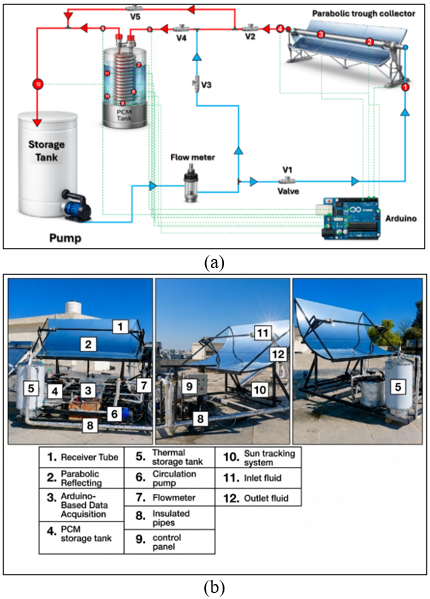
The experimental system comprised a PTC, a PCM storage unit with a helical-coil heat exchanger, a pump, a flow meter, a water storage tank, and an Arduino-based data acquisition system, as shown schematically in Figure 1(a) and photographically in Figure 1(b). Water was used as the HTF. Table 2 describes the main specifications of the experimental rig.
Table 2. Main specifications of the experimental system
|
Parameter |
Specification |
|
Collector type |
Parabolic trough collector (PTC) |
|
Collector dimensions |
2 m × 2 m; aperture area = 4 m² |
|
Reflector/support structure |
Aluminum sheet/steel frame |
|
Receiver |
Evacuated borosilicate glass tube, Type 58 |
|
Receiver dimensions |
Length = 1800 mm; OD = 58.5 mm; ID = 44.5 mm; glass thickness = 0.6 mm |
|
Absorber tube |
Copper; length = 175 cm; diameter = 28 mm |
|
HTF |
Water |
|
Absorber coating/experimental location |
Black coating/Kirkuk, Iraq |
Figure 1. Experimental parabolic trough collector–phase change material (PTC–PCM) thermal energy storage system: (a) schematic diagram, (b) photograph of the fabricated experimental setup
2.4 Phase change material storage unit
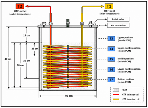
The cylinder-shaped thermal energy storage unit was integrated with the PCM to improve the PTC system's thermal energy storage capacity. This thermal energy storage tank was fabricated using steel due to its mechanical strength and durability. Its height was 40 cm, while the outer diameter was 40 cm. Paraffin wax was chosen as the PCM owing to its high latent heat storage capacity, stability, compatibility, and suitable melting point for the production of domestic hot-water. Some of the main characteristics of the PCM utilized are presented in Table 3. The 30 kg PCM mass was adopted as the full nominal PCM charge of the fabricated storage unit. Accordingly, 10 and 20 kg were selected to represent approximately one-third and two-thirds of this nominal capacity, respectively. These three loading levels provided low, intermediate, and full PCM quantities while maintaining the same storage-tank geometry, double-helical-coil configuration, PCM type, and operating conditions. This selection enabled isolation of the effect of PCM mass and provided a practical basis for evaluating the trade-off among thermal storage capacity, thermal response, and heat-supply duration. The HTF circulated through a double-helical copper-coil heat exchanger embedded in the PCM storage tank, as shown in Figure 2. This arrangement was chosen due to its higher heat-transfer characteristics and better temperature distribution than the straight tubes [23]. The tank was thermally insulated to minimize heat losses. K-type thermocouples connected to MAX6675 modules monitored the water temperatures at the PTC inlet and outlet, the absorber-tube surface temperature, the coil inlet and outlet temperatures, the PCM temperature at different locations within the storage unit, and the storage-tank inlet temperature, as indicated in Figure 2.
Table 3. Thermophysical properties of paraffin wax used as phase change material (PCM) [24]
|
Property |
Value |
|
Melting temperature |
44 ℃ |
|
Latent heat of fusion |
190 kJ/kg |
|
Solid density |
930 kg/m3 |
|
Liquid density |
830 kg/m3 |
|
Thermal conductivity |
0.21 W/(m‧℃) |
|
Specific heat capacity |
2.1 kJ/(kg‧℃) |
Figure 2. Schematic diagram of the phase change material (PCM) thermal energy storage unit with thermocouple locations
2.5 Thermal energy analysis
The theoretical amount of heat stored in the PCM was calculated using Eq. (1).
$\begin{gathered}Q_{\text {stored}}=m_{\text {pcm}}\left[c p_{\text {pcm}, s}\left(T_m-T_i\right)+H_{\text {pcm}}\right.\left.+c p_{\text {pcml}}\left(T_f-T_m\right)\right]\end{gathered}$ (1)
where, $m_{p c m}$ is the PCM mass, $H_{p c m}$ is the latent heat of fusion, $T_i, T_m$, and $T_f$ are the initial, melting, and final temperatures, respectively, and $c p_{p c m, s}$ and $c p_{p c m l}$ are the are the specific heat capacities of the solid and liquid PCM, respectively. Sensible heat was evaluated over the temperature range of 18–64 ℃. The rate of heat supply or extraction for the HTF [23] was calculated using Eq. (2):
$Q F=\dot{m}_{H T F} C_{P, H T F} \Delta T_F$ (2)
The total energy supplied or recovered by the HTF during charging and discharging was calculated using Eq. (3):
$Q f t=\sum \Delta t \times Q f$ (3)
where, $\dot{m}$ is the HTF mass flow rate, $C_{P, H T F}$ is the specific heat capacity of the HTF, and $\Delta T_F$ is the temperature difference between the HTF inlet and outlet.
2.6 Uncertainty
Experimental uncertainty was evaluated for the measured temperature, flow rate, and solar irradiance. The uncertainty is calculated by Eq. (4):
$\begin{aligned} & U_R^2=\left[\left(\partial \mathrm{R} /\left(\partial \mathrm{x}_1\right) \Delta \mathrm{x}_1\right)^2+\left(\partial \mathrm{R} /\left(\partial \mathrm{x}_2\right) \Delta \mathrm{x}_2\right)^2\right. \left.+\ldots \ldots \ldots+\left(\partial \mathrm{R} /\left(\partial \mathrm{x}_{\mathrm{n}}\right) \Delta \mathrm{x}_{\mathrm{n}}\right)^2\right]\end{aligned}$ (4)
where, UR is the combined uncertainty in the calculated result R, xi is the ith independent variable, Δxi is its associated uncertainty, and ∂R/∂xi represents the sensitivity of R to xi.
The uncertainty for the temperature difference was calculated by applying Eq. (5).
$\delta(\Delta T)=\sqrt{ }\left[(\delta \text {Tin})^2+(\delta \text {Tout})^2\right]$ (5)
where, δ(ΔTf) is the uncertainty in the HTF temperature difference, while $\delta \operatorname{Tin}$ and $\delta \operatorname{Tout}$ are the uncertainties associated with the inlet and outlet temperature measurements, respectively.
The calculated uncertainties were within acceptable experimental limits. Experimental uncertainty was evaluated for the measured temperature, flow rate, and solar irradiance, with uncertainties of ±2 ℃, ±0.1 L/min, and ±5%, respectively. The uncertainty in the calculated results was estimated using Eq. (4), where UR represents the uncertainty in the calculated result R, and x denotes the independent variable. The uncertainty in the temperature difference was determined using Eq. (5). The calculated uncertainties were within acceptable experimental limits.
2.7 Numerical investigation
2.7.1 Computational geometry and mesh generation
The exact geometry of the experimental storage system unit is designed and built using the design modeler.
The fluid domain geometry consists of two geometric arrangements – one is a helical coil domain, and another is a PCM domain.
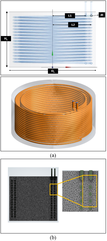
Additionally, thermal energy transfer occurs from the HTF (water) through two helical copper coils, which are arranged in a concentric arrangement—one large helical coil on the outside and one small helical coil inside. The helical radius of the inner coil (L1) is 150 mm, while that of the outer coil (L2) is 175 mm. The diameter (di) of each tube in the coils is 9 mm. Heat transfer begins with water entering the helical outer coil from the top and then flowing down along the helical path into the inner helical coil; finally, it exits from the inner helical coil at the top end of the tank. The series arrangement ensures the full temperature profile of the HTF interacts with the PCM across both the radial and axial extents of the storage vessel, as shown in Figure 3.
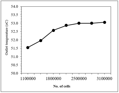
In order to make sure that the results obtained through numerical calculation do not depend on the grid used, the grid independence test was carried out on seven different meshes, with numbers varying from 1,110,000 to 3,100,000 cells. Outlet temperature was chosen as the criterion for the analysis. It was established that the fluctuation in temperature was insignificant starting from 2,500,000 cells. Thus, 2,500,000 cells were taken as the optimal mesh number, as shown in Figure 4.
Figure 3. (a) Computational geometry of the phase change material (PCM) storage unit, (b) meshing of the numerical model
Figure 4. Mesh sensitivity study
2.7.2 Boundary conditions
The HTF inlet was defined as a mass-flow inlet with a constant mass flow rate of 0.0167 kg/s, corresponding to the experimental flow rate of 1 L/min. The inlet temperature was specified as a time-dependent condition based on the experimentally measured PTC outlet temperature. The water outlet was set as a pressure outlet at 0 Pa gauge pressure. Because the storage tank was thermally insulated, its external walls were treated as adiabatic with zero heat flux (0 W/m²). The water–copper and copper–PCM interfaces were defined as coupled walls to allow heat transfer between the HTF, copper coil, and PCM without additional interfacial thermal resistance.
2.7.3 Governing equations
The CFD model solves the time-dependent, 3-D conservation equations of mass, momentum, and energy for incompressible laminar flow in the HTF domain, coupled with the enthalpy–porosity formulation for phase change. The thermophysical properties of the materials were treated as constant, except for the density variation associated with buoyancy, which was represented using the Boussinesq approximation. Therefore, natural convection in the molten PCM was included in the numerical model. The continuity equation for incompressible flow is calculated by Eq. (6):
$\frac{\partial u_{\mathrm{i}}}{\partial x_{\mathrm{i}}}=0$ (6)
The momentum equation, incorporating the Boussinesq buoyancy term and the Carman–Kozeny source term for the mushy zone, is calculated by Eq. (7):
$\begin{gathered}\rho\left(\frac{\partial u_i}{\partial t}+u_j \frac{\partial u_i}{\partial x_j}\right)=-\frac{\partial P}{\partial x_i}+\frac{\partial}{\partial x_i}\left[\mu\left(\frac{\partial u_i}{\partial x_i}\right)\right]+\rho g \beta\left(T-T_{r e f}\right) \delta_i^2+S_i\end{gathered}$ (7)
where, the source term Sᵢ is the Carman–Kozeny drag term used in the enthalpy–porosity method, Eq. (8):
$S_{\mathrm{i}}=-A_{\text {mush}} \cdot \frac{(1-\gamma)^2}{\left(\gamma^3+\varepsilon\right)} \cdot u_{\mathrm{i}}$ (8)
Here, γ ∈ [0, 1] is the liquid fraction, $A_{\text {mush}}$ is the mushy-zone constant [kg·m⁻³·s⁻¹], and ε equals 10⁻³, which is a small constant preventing division by zero.
The energy equation is written in terms of total enthalpy H, Eq. (9):
$\frac{\partial(\rho H)}{\partial t}+\nabla \cdot(\rho u H)=\nabla \cdot(k \nabla T)$ (9)
Total enthalpy is decomposed into sensible and latent contributions, Eq. (10):
$H=h+\Delta H=\int c_p d T+\gamma L$ (10)
where, h is the sensible enthalpy, L is the latent heat of fusion, and γ is the liquid fraction defined by the piecewise linear relation, Eqs. (11)-(13):
$\gamma=0$ if $T<T_{\text {solidus}}$ (11)
$\gamma=\frac{\left(T-T_{\text {solidus}}\right)}{T_{\text {liquidus}}-T_{\text {solidus}}}$ if $T_{\text {solidus}} \leq T \leq T_{\text {liquidus}}$ (12)
$\gamma=1$ if $T>T_{\text {liquidus}}$ (13)
The mushy region for a pure PCM reduces to a melting point only, that is, $T_{\text {solidus}}=T_{\text {liquidus}}=T_m$, and a narrow temperature region can be defined for stability purposes. The model for solidification and melting in ANSYS Fluent is based on the formulation in the literature [25].
2.7.4 Solver configuration and numerical scheme
Pressure-based transient analysis was used in ANSYS Fluent for modeling the charging and discharging operations. A laminar flow model was adopted as a simplifying assumption for the present numerical analysis. Natural convection in the molten PCM was accounted for through the Boussinesq approximation with gravity enabled. The laminar formulation was retained to provide a consistent computational framework, while its possible influence on the predicted HTF-side heat transfer is acknowledged. The energy equation, along with an enthalpy-porosity-based solidification-melting model, was included for modeling the phase change phenomenon. Coupling of pressure and velocity fields was accomplished via the SIMPLE algorithm, and a second-order upwind scheme was used for the momentum and energy equations, as shown in Table 4.
Table 4. Numerical solver settings and discretization schemes used in ANSYS Fluent
|
Solver Option |
Setting/Value |
|
Solver type |
Pressure-based, transient (implicit) |
|
Gravity |
−9.81 m·s⁻² in the Y-direction |
|
Turbulence/flow model |
Laminar |
|
Energy equation |
Enabled |
|
Phase-change model |
Solidification & Melting (Voller–Prakash enthalpy–porosity) |
|
Pressure–velocity coupling |
SIMPLE |
|
Pressure discretisation |
PRESTO! |
|
Momentum discretisation |
Second-order upwind |
|
Energy discretisation |
Second-order upwind |
|
Transient formulation |
First-order implicit (time stepping) |
|
Convergence criteria |
10⁻³ (continuity, momentum); 10⁻⁶ (energy) |
|
Max. iterations/time step |
20 |
|
Time-step strategy |
Δt = 0.5 s (initial), progressively increased while maintaining convergence |
|
Total simulation period |
08:00 (Day 1) → 08:00 (Day 2) = 24 h |
The assumption of constant thermophysical properties represents a numerical simplification, since the properties of the HTF and PCM may vary with temperature.
This assumption may bring deviations in the forecast local temperature distribution, heat-transfer rate, and PCM melting behavior. Similarly, under conditions near the transitional regime, the laminar-flow assumption can impact predicted HTF-side convective heat transfer. However, all the assumptions for the numerical model were satisfied, since it replicates the experimental temperature behavior well by showing that the basic thermal response and phase-change characteristics of the present system are adequately described.
3.1 Experimental results
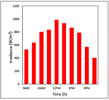
Figure 5 shows the variation of solar irradiance (W/m²) during work time. Solar irradiance increased from the morning to a maximum of about 980 W/m² around noon and then decreased in the afternoon. Since there is a considerable amount of high solar irradiance from 11:00 AM to 2:00 PM, more thermal energy input has been absorbed by the PCM storage system.
Figure 5. Variation of solar irradiance with time
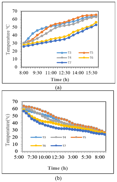
The charging and discharging temperature profiles for the 30 kg PCM case – full nominal storage capacity – are shown in Figure 6. The PCM temperatures gradually increased when charged, and locations closest to the helical coil responded fastest due to a shorter heat-transfer path. Upon discharge, the temperature dropped gradually as the stored sensible and latent heat was released, and the observations between thermocouples corresponded relative to their distances from the coil. For the 10 and 20 kg cases, thermal behavior followed similar patterns but with different response times (the smaller, lower capacity case charged and cooled faster; the intermediate mass case showed intermediate behavior). On the other hand, due to its larger thermal storage capacity, the 30 kg case exhibited a lower response during charging but a higher heat release duration. CFD results are used to give a more precise interpretation of the heat-transfer and phase-change mechanisms, which is formulated in Section 3.2.
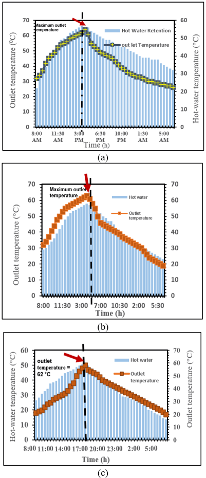
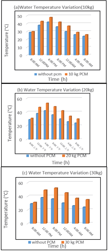
Figure 7 compares the outlet and storage-tank temperature behavior for the 10, 20, and 30 kg PCM cases during charging and discharging. The results show that increasing PCM mass prolonged the period over which the outlet and stored-water temperatures remained at useful levels. The 10 kg case exhibited a faster decrease in temperature, whereas the 20 and 30 kg cases maintained elevated temperatures for longer periods because of their greater thermal storage capacity. Among the investigated cases, the 30 kg PCM mass provided the longest post-sunset heat-supply duration, while the 20 kg case showed intermediate performance. These results confirm that PCM mass has a direct influence on the duration of useful thermal energy delivery from the storage system.
Figure 6. Charging and discharging temperature profiles of the 30 kg phase change material (PCM) case: (a) charging, and (b) discharging
Figure 7. Temporal variation of the phase change material (PCM) outlet and storage-tank temperatures during charging and discharging for: (a) 30 kg PCM, (b) 20 kg PCM, and (c) 10 kg PCM
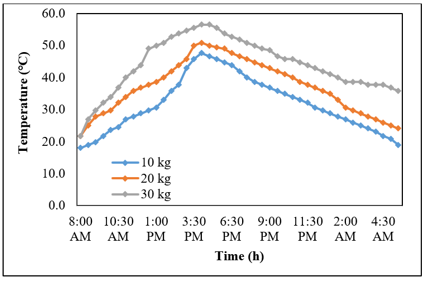
Figure 8. Effect of phase change material (PCM) mass on the storage-tank temperature over 24 h
Moreover, Figure 8 compares the thermal behavior of the storage system for the three PCM masses over 24 h. Increasing PCM mass prolonged the discharge period and hot-water availability, whereas the charging time changed only moderately. The 10 kg case exhibited the fastest thermal response but the shortest heat-retention period, while the 30 kg case provided the longest heat supply owing to its greater sensible and latent heat-storage capacity. The 20 kg case showed intermediate behavior. Because the same double-helical-coil heat exchanger was used for all cases, increasing PCM mass required a larger amount of material to be heated through the same heat-transfer surface, resulting in a slower thermal response. Therefore, PCM mass should be selected according to the required balance between storage capacity, response time, and heat-supply duration.
Additionally, the experimentally determined thermal energy recovery efficiency was calculated as the ratio of the energy recovered by the HTF during discharge to the energy supplied by the HTF during charging. Accordingly, the thermal energy recovery efficiency was calculated using Eq. (14) [23].
$\mu=\frac{\text {Qrecovered}}{\text {Qsupplied}}=\frac{\text {Qdischarging}}{\text {Qcharging}}$ (14)
The thermal energy recovery efficiency of the PCM storage unit was evaluated based on the amount of thermal energy recovered during the discharge process. From the above results, it is evident that the heat recovery efficiency was found to increase due to the increase in the mass of PCM, starting at 41.7% with 10 kg of PCM, to 55% with 20 kg of PCM, and finally to 66.8% with 30 kg of PCM, as summarized in Table 5. The improvement in heat recovery efficiency is mainly due to the enhanced capacity of heat storage in higher PCM mass. To provide a clearer quantitative assessment of the practical effect of PCM mass, the main thermal performance indicators for the 10, 20, and 30 kg cases are summarized in Table 5.
Table 5. Quantitative comparison of the thermal performance for different phase change material (PCM) masses
|
Parameter |
PCM Mass |
||
|
10 kg |
20 kg |
30 kg |
|
|
Stored thermal energy (kWh) |
2.5 |
3.6 |
4.2 |
|
Thermal energy recovery efficiency (%) |
41.7 |
55.0 |
66.8 |
|
Thermal response |
Faster |
Intermediate |
Slower |
|
Practical interpretation |
Lower storage capacity with lower PCM requirement |
Balanced storage capacity and thermal response |
Highest storage capacity and recovery efficiency, with greater PCM requirement |
Without PCM, useful hot-water availability was maintained for approximately 2 h, whereas the retention period increased to approximately 4, 6, and 8 h for the 10, 20, and 30 kg PCM cases, respectively. This improvement is attributed to the increased sensible and latent heat-storage capacity at higher PCM masses, which enables stored thermal energy to be released over a longer period after solar input decreases. Consequently, the 30 kg case provided the longest hot-water retention, while the 20 and 10 kg cases showed intermediate and shorter durations, respectively.
Figure 9 further demonstrates the effect of PCM mass on hot-water retention.
Figure 9. Comparison of storage-tank water temperature with and without phase change material (PCM) at different PCM masses
3.2 Numerical results
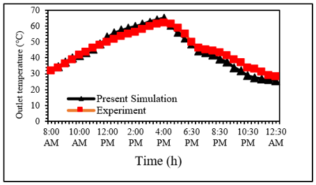
The numerical model was validated against the current experimental data of the HTF outlet temperature recorded from 8:00 AM to 12:30 AM the following day. The comparison between the simulated and experimentally measured outlet temperatures is presented in Figure 10. Overall, the CFD model reproduces the experimentally observed thermal behavior with good fidelity across the charging and discharging processes. These results confirm that the numerical model is sufficiently validated for interpreting the heat-transfer and phase-change mechanisms in the 30 kg PCM case.
Figure 10. Validation of the numerical results against the experimental results
The small deviations between the numerical and experimental results may be attributed to variations in the actual thermophysical properties of the PCM with temperature, experimental measurement uncertainties, and simplifications adopted in the numerical model. The experimental uncertainties were ±2 ℃ for temperature, ±0.1 L/min for flow rate, and ±5% for solar radiation.
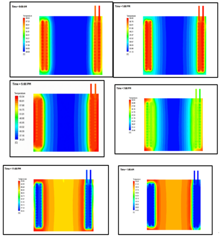
Also, assumptions of constant thermophysical properties, laminar flow, and idealized boundary conditions may lead to discrepancies. It has been observed that the predicted trend of outlet temperature was in good agreement with experimentally obtained data, which shows that CFD simulation can efficiently be used to carry out heat transfer and phase change at a PCM storage unit. A time-dependent form of temperature contour is shown in Figure 11. This is to clarify the phase transition, which was not visible in the fully covered storage system.
Figure 11. Temperature contours within the phase change material (PCM) storage unit during the charging and discharging processes at different times: (a) 9:00 AM, (b) 1:00 PM, (c) 5:00 PM, (d) 7:00 PM, (e) 11:00 PM, and (f) 1:00 AM
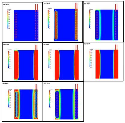
Figure 12. Evolution of phase change material (PCM) liquid-fraction contours during charging and discharging at different times: (a) 9:00 AM, (b) 11:00 AM, (c) 1:00 PM, (d) 3:00 PM, (e) 5:00 PM, (f) 7:00 PM, (g) 9:00 PM, (h) 11:00 PM
The 30 kg case CFD results provide a physical explanation for the thermal responses observed experimentally. Figure 12 shows that the PCM next to the helical coil first heats and melts, while further away from the heat-transfer surface are slow-moving. This indicates that heat transfer is initially governed mainly by conduction near the coil, followed by buoyancy-driven natural convection as the liquid PCM region develops. During discharge, solidification begins near the heat-transfer surface, and the growing solid PCM region increases the effective thermal resistance, thereby reducing the heat-transfer rate. The importance of thermal resistance in controlling PCM phase-change performance has also been reported by Opolot et al. [26]. Although the CFD simulation was performed only for the 30 kg case, these physical mechanisms help interpret the experimental differences among the 10, 20, and 30 kg cases. With the same helical-coil heat-transfer surface, the 10 kg case requires less energy to heat and melt the PCM and therefore shows a faster thermal response but a shorter heat-release duration; the 20 kg case exhibits intermediate behavior; and the 30 kg case has greater sensible and latent heat capacity and thermal inertia, leading to a slower thermal response but longer heat retention and discharge duration.
This study experimentally investigated the effect of PCM mass on the thermal performance of a PTC integrated with a PCM-based thermal energy storage unit under real outdoor climatic conditions in Kirkuk, Iraq. Three paraffin wax masses of 10, 20, and 30 kg were examined, while a three-dimensional transient CFD model was developed and validated for the 30 kg case. The following are the main findings:
According to the above, the right amount of PCM should be chosen depending on what is needed for the specific solar thermal application rather than simply maximizing this amount. A lower PCM mass may be preferred when faster thermal response, lower storage-space requirement, and lower PCM material demand are important, whereas a higher PCM mass is more suitable when greater storage capacity and extended post-sunset heat supply are required. The 20 kg case provides an intermediate balance between these characteristics. Therefore, the present results should be regarded as a comparative design assessment within the investigated PCM mass range rather than a formal economic or mathematical optimization.
The authors would like to express their gratitude to the Northern Technical University for their logistical support.
[1] Abed, T.H., Yaseen, T.A., Awad, A.T. (2026). Experimental and numerical simulation of smart nanofluid-enhanced solar thermal systems for energy-efficient and hot climate building. Applied Nanoscience, 16(3): 29. https://doi.org/10.1007/s13204-026-03166-6
[2] Mohammed, Z.R., Awad, A.T., Ajisegiri, G.O. (2026). Advances in solar collector system under the Kirkuk city climatic condition. NTU Journal of Renewable Energy, 10(1): 100-110. https://doi.org/10.56286/hzf4d787
[3] Hamdoon, A.A., Awad, A.T. (2026). The use of nanotechnology in improving efficiency of desalination systems by solar energy. AIP Conference Proceedings, 3396(1): 090007. https://doi.org/10.1063/5.0318263
[4] Hamdoon, A.A., Awad, A.T. (2024). Insight review on solar still application. World Journal of Environmental Research, 14(2): 145-153. https://doi.org/10.18844/wjer.v14i2.9605
[5] Awad, A.T., Albazzaz, K.J.T. (2022). Numerical investigation of a high-temperature energy storage. MINAR International Journal of Applied Sciences and Technology, 4(4): 133-146. http://doi.org/10.47832/2717-8234.13.12
[6] Awad, A., Hussein, A. (2024). Influence of nanofluid types on the enhancements of solar collector performance. International Innovations Journal of Applied Science, 1(2). https://doi.org/10.61856/f7m6ty09
[7] Awad, A.T., Gahfour, M.H., Hussein, A.M., Said Al Rahbi, A.S., Bentham, E. (2024). CFD analysis of convective heat transfer for nanoparticles and porous medium. International Review of Mechanical Engineering, 18(8): 406. http://doi.org/10.15866/ireme.v18i8.24702
[8] Awad, A.T., Muayad, M.W. (2023). Experimental heat transfer study of an enhanced storage medium. Journal of Energy Storage, 73: 108953. https://doi.org/10.1016/j.est.2023.108953
[9] Awad, A.T., Taifor, M.N., Yaseen, A.H., et al. (2025). Enhanced energy storage via one-step preparation of Cuo-nanosalt. The European Physical Journal Plus, 140(10): 995. https://doi.org/10.1140/epjp/s13360-025-06924-7
[10] Raja, S., Prakash, S., Gokulnath, R., Krishnamoorthy, A., Lillymercy, J. (2018). PCM based thermal energy storage system integrated with solar parabolic trough collector. Journal of Engineering Science and Technology, 13: 40-51.
[11] Nagappan, B., Alagu, K., Devarajan, Y., Munuswamy, D.B. (2018). Energy and exergy analysis of multi-temperature PCMs employed in a latent heat storage system and parabolic trough collector. Journal of Non-Equilibrium Thermodynamics, 43(3): 211-220. https://doi.org/10.1515/jnet-2017-0066
[12] Guerraiche, D., Bougriou, C., Guerraiche, K., Valenzuela, L., Driss, Z. (2020). Experimental and numerical study of a solar collector using phase change material as heat storage. Journal of Energy Storage, 27: 101133. https://doi.org/10.1016/j.est.2019.101133
[13] Lamrani, B., Kuznik, F., Draoui, A. (2020). Thermal performance of a coupled solar parabolic trough collector latent heat storage unit for solar water heating in large buildings. Renewable Energy, 162: 411-426. https://doi.org/10.1016/j.renene.2020.08.038
[14] Malekpour, A., Ahmadi, R., Sadeghzadeh, S. (2021). In situ latent thermal energy storage in underfloor heating system of building connected to the parabolic trough solar collector-An experimental study. Journal of Energy Storage, 44: 103489. https://doi.org/10.1016/j.est.2021.103489
[15] Mhedheb, T., Hassen, W., Mhimid, A., Almeshaal, M.A., Alhadri, M., Kolsi, L. (2023). Parametric analysis of a solar parabolic trough collector integrated with hybrid-nano PCM storage tank. Case Studies in Thermal Engineering, 51: 103652. https://doi.org/10.1016/j.csite.2023.103652
[16] Colarossi, D., Rghif, Y. (2024). Optimization of the mass ratio and melting temperature of PCMs integrated in salt gradient solar ponds. Solar Energy Materials and Solar Cells, 269: 112786. https://doi.org/10.1016/j.solmat.2024.112786
[17] Zhang, Y., Zhang, W. (2024). Research and optimisation of focused solar heating system with phase change thermal storage. Frontiers in Energy Research, 12: 1279491. https://doi.org/10.3389/fenrg.2024.1279491
[18] Karaağaç, M.O., Akıncı, B., Ergün, A. (2024). Enhancing the performance of parabolic trough solar collectors: Cost-effective innovative designs for sustainable energy harvesting. Applied Thermal Engineering, 253: 123693. https://doi.org/10.1016/j.applthermaleng.2024.123693
[19] Saleh, E.M., Hameed, V.M. (2024). Innovative new solar parabolic trough collector enhanced by corrugated receiver surface with PCM and turbulator inside. Journal of Energy Storage, 86: 111403. https://doi.org/10.1016/j.est.2024.111403
[20] Kumar, B., Awasthi, A., Lee, J., Jeon, Y. (2025). Numerical analysis of absorber tube shapes in PCM-integrated parabolic trough solar collectors. Case Studies in Thermal Engineering, 66: 105783. https://doi.org/10.1016/j.csite.2025.105783
[21] Abdelaziz, N., Bouali, B., Guerraiche, D., Zaitri, T. (2026). Phase change material integration in elliptical double-tube receivers: A novel approach to reduce thermal stress and boost energy storage in parabolic trough collectors. Journal of Mechanical Science and Technology, 40(3): 2239-2252. https://doi.org/10.1007/s12206-026-0259-0
[22] Rashid, M.K., Abas, A., Awad, A.T. (2026). Macro-encapsulated phase change materials for latent heat storage: Design innovations, performance enhancement, and application insights. Journal of Energy Storage, 160: 121573. https://doi.org/10.1016/j.est.2026.121573
[23] Saydam, V., Parsazadeh, M., Radeef, M., Duan, X. (2019). Design and experimental analysis of a helical coil phase change heat exchanger for thermal energy storage. Journal of Energy Storage, 21: 9-17. https://doi.org/10.1016/j.est.2018.11.006
[24] Sulaiman, H.S., Abbas, E.F., Tahseen, T.A. (2021). Assessment of the thermal performance of hybrid PVT collector by integrating it with a PCM storage unit. International Journal of Renewable Energy Research, 11(3): 1043-1052.
[25] Voller, V.R., Prakash, C. (1987). A fixed grid numerical modelling methodology for convection-diffusion mushy region phase-change problems. International Journal of Heat and Mass Transfer, 30(8): 1709-1719. https://doi.org/10.1016/0017-9310(87)90317-6
[26] Opolot, M., Zhao, C., Liu, M., Mancin, S., Bruno, F., Hooman, K. (2021). Investigation of the effect of thermal resistance on the performance of phase change materials. International Journal of Thermal Sciences, 164: 106852. https://doi.org/10.1016/j.ijthermalsci.2021.106852