Sura Nawfal Abdulrazzaq
© 2026 The author. This article is published by IIETA and is licensed under the CC BY 4.0 license (http://creativecommons.org/licenses/by/4.0/).
OPEN ACCESS
This paper implements a conflict-aware fully parallel Delaunay triangulation algorithm to produce triangular meshes designed for the Graphic Processing Unit (GPU), ensuring high geometric quality and computational efficiency comparing to the traditional methods, unlike these methods or even batch-based approaches, the proposed work leverages massively parallel point insertion using modified Bowyer–Watson and localized Lawson edge flipping methods, where each point is processed independently within a unified execution flow as a thread-level parallelism (TLP), in addition to implementing a local stabilized flipping stage that eliminates the global barrier and resolves the concurrent flipping by many threads which may consume extra time. A lightweight conflict-handling strategy based on atomic operations is used to process concurrency issues arising from the parallelism. This complete design reduces overhead on kernel launch and improves hardware utilization while preserving triangle correctness. The implementation is built using Compute Unified Device Architecture (CUDA/C++) and Graphic Library interoperability for directly visualizing the mesh triangles, in which synthesis and real-world datasets are used to evaluate the method performance. Experimental results and thorough comparisons achieve a maximum speedup of ×30 and ×13 compared to sequential, traditional triangulation respectively, even for complex point distribution, highlighting the effectiveness of the design.
atomic operations, conflict handling, Delaunay, edge flipping, Graphic Processing Unit, triangulation
Triangulation is a fundamental geometric structure widely used in computer graphics that is considered one of the more attractive research topics in computational geometry. It is widely employed in a plethora of areas, such as terrain modeling [1], aerospace engineering [2], mining engineering [3], vision and robotic systems [4], in addition to data visualization and computer graphics [5], which are the most relied fields among others for triangulated surface representation.
A triangulation of the set $V=\left\{v \in \mathbb{R}^2\right.$ or $\left.\mathbb{R}^3\right\}$ produces triangles with vertices selected from V under the condition that edges of the triangles do not intersect and no overlap occurs between them [6]. The Delaunay Triangulation (DT) extends the process by additional properties producing well-shaped triangles while ensuring better numerical stability compared with arbitrary triangulations, this is achieved by checking that no vertex from set V lies inside the circumcircle of the triangle while adding a new vertex, as well as maximizing the minimum angle [6, 7].
Processing large vertices of surface meshing is considered a central bottleneck in the graphics pipeline and real-time visualization. Notably, for a real-world data set such as point cloud or terrain data that habitually has hundreds of thousands to millions of vertices [8]. The increasing amount of geometric data has created a growing need for an efficient mesh triangulation method, which is an essential process for representing surfaces.
Traditional triangulation and mesh-generation methods become excessively cost-prohibitive, as many of them was originally designed for sequential execution, which leads to a worse runtime making interactive and real-time applications unrealistic on a single threaded execution.
Toward achieving the parallelism and speeding up mesh generation, the (DT) is the most adopted among other methods according to its independent processing of high-quality surfaces, in contrast to an ear clipping algorithm, which produces triangles by cutting off ears iteratively from a polygon [9]. The classical (DT) or (Delone) triangulation analyzes each candidate vertex upon the Delaunay circumcircle test (mainly the empty circumcircle property). However, it comprises many classical serial algorithms like gift-wrapping [10], the Sweep-line [11, 12], and the divide and conquer [13] algorithms, which are well-known and robust; even so, they have become unsuitable to handle large data or meet the increasing demands of realistic scenes.
Despite available research on DT, several challenges still unsolved, especially in achieving efficient parallelism and scalable performance for large datasets. Many existing approaches is concerned with either theoretical improvements to enhance the quality of generated triangles themselves, or sequential or even low-level parallel implementations, many of these works are with limited practical frameworks that support rapid prototyping.
Moreover, little attention has been given to implement parallel triangulation-based high-level engineering platforms such as CUDA-OpenGL (Compute Unified Device Architecture-Open Graphic Library), where low-latency analysis and integration efficiency are critical. To address these gaps, this paper aims to build efficient Delaunay-based triangulation framework that leverages CUDA GPU (Graphic Processing Unit) architecture to enable parallel execution, including parallel flipping to maintain geometry accuracy. The key contribution of this research is threefold:
The remainder of this paper is presented as follows: Section 2 reviews the related works on DT and its sequential and parallel implementation on ℝ2, followed by the detailed concepts and definitions of DT in Section 3. Section 4 describes the proposed methodology and parallel algorithms. In Section 5 the experimental performance results and their visualization analysis are presented. Finally, Section 6 concludes the work and highlights future research directions.
In recent years, the formation of triangulated meshes has garnered significant attention from researchers, this section addresses the Delaunay approaches by their types and improvements, focusing on the modern versions that parallelize the algorithm, for other aspects and details the reader may refer to the recent survey by Elshakhs et al. [14]. We composed the related works into three categories according to their algorithmic strategy and level of computational concurrency.
2.1 Sequential Delaunay literature
This category includes the traditional formulation that can be divided- according to the construction methods- in to three types: gift-wrapping [10], the Sweep-line [11, 12], and the divide and conquer [13] algorithms. All of these algorithms achieve the empty circumcircle property that was previously mentioned. Among them the growth incremental approach proposed by Watson-Bowyer became the most widely adopted due to its robustness where the vertices are inserted one after another, compared to the divide and conquer that recursively partitions the regions and merges them, or the complexity of moving the frontier in linear order to traverse the vertices in the sweep-line algorithm.
During the 2000s, research attention moved toward improving the quality of generated triangles by enhancing mesh regularity, as in the study [15] that enhances geometric predicates using internal arithmetic to avoid numerical errors, where it presents a best-known Computational Geometry Algorithms library (CGAL) in many versions written by C++ on ℝ2, It is considered the baseline reference for evaluating other new triangulation algorithms due to its numerical robustness and correctness guarantees. It has recently been expanded to (v6.1 2025) [16], that uses a refinement stage by producing vertices at the centers of the circumcircles of bad triangles as in the study [17]. However. it remains sequential as in the previous versions.
Post-2020 research has primarily focused on 2D point sets such as iterative void characteristics and morphological contours [18, 19], the latter generated 2D binary microstructure images using Constrained Delaunay Triangulation (CDT) that violet the Delaunay property condition.
Although the reliability has been improved in many of these works, the long processing time remains the drawback, and the researchers did not alter the sequential nature. This inspires researchers to other different strategy to move toward concurrent implementation on different hardware as FPGA [20], multi-core [21-24] and GPU [25-31]. In these literatures, we observe that there are two directions to implement the parallel DT algorithm according to the granularity.
2.2 Coarse-grained parallelism literature
These works partition the domain into smaller regions and triangulate each one independently, followed by another step to merge or stitch these triangles to restore the final Delaunay mesh. Most studies adopting this parallelism type have been explicitly designed for multi-core or multi-node systems [9, 21, 22], and [23] where they exploited the divide-and-conquer algorithm that fits on the partitioning and achieved good scalability. Nguyen and Rhodes [21] also introduced a novel extended method to triangulate Independent Partitions in Parallel (TIPP) employing multiple supervisory processes, balancing the computational load among several machines and performing boundary refinement to ensure a corrected mesh across partitions, the design could produce 20 billion 2D triangles using only ten commodity computing nodes in 30 minutes.
The authors in the study [22] applied the same partitioned strategy but on digitized point cloud data, they got a parallel running time of about 5 minutes to produce 809 triangles using 4-cores. Other works [23, 24] also triangulated data acquired by airborne LiDAR on multi-core, but their design is built upon both divide and conquer and Bowyer-Watson algorithms on different CPU cores to produce 2D triangles, In the study [23] the maximum performance was about 240 sec. to process 21 million points, while, GeoKSCloud computing environment that is used in the study [24] yielded about 300 thousand triangles during 38 seconds on 6 nodes.
On the other hand, few works have exploited GPU for the acceleration, Carter et al. [25] computed the DT for simulating Brownian particles, where it employed the DT combining with parallel edge-flipping to resolve particle overlaps, their results showed a performance improvement of up to two orders of magnitude when compared to the previously existing sequential solution. Ray et al. [26] proposed a parallelizable GPU algorithm to compute VD (Voronoi Diagram), which returns only the geometry of the Voronoi cells rather than a combinatorial mesh data structure. Zahida et al. [27] also introduced a partitioning strategy of parallel DT for K-means clustering data, attempting to improve load balance on these distributions compared to conventional cell or octree methods.
Although this granulated parallelism improves the traditional DT algorithm by decomposing it to several groups, the speedup is still constrained by the merging computational overhead and unbalanced distribution of triangles, in addition to the complexity of connecting the subregions and identifying the triangles that have to be modified to satisfy the Delaunay condition after merging. So, these corrections affect the whole triangulation, even exploiting GPUs is somewhat inefficient in this strategy since it uses many small cores, thereby increasing the stitching time to form the final triangle mesh.
Recently, an approach is introduced to limit the merging of combined sub-triangles using forest-of-overlapping-trees approach by extending the origin distributed region for each processor by about (δ) meshes [28], which gives the approach its ability to generate meshes independent of processor count, however, this requires additional communication cost and synchronization between neighbouring data, in addition of the problem of the missed intersection for small δ.
2.3 Fine-grained parallelism literatures
In the second parallelism direction of DT, few recent works try to overcome the complex merging process by a single-shared mesh, which needs careful synchronization and conflict operations. Kallis et al. [20] explore akin to this parallelism on FPGA/ C++ producing (2D) planners, A major strength of the work is its efficient utilization of FPGA parallel resources for geometric reconstruction of real-world graphics models, however, the incircle and insertion tests still sequential in nature and the synchronization is handled by simple hardware scheduling, this design lacks support for dynamic conflict mechanisms, making it less scalable compared to GPU-based parallel insertion approaches.
Other works employ this type of parallelism but on initial triangles [29] or lines [30] rather than points, Coll and Guerrieri [30] also produced a planar straight-line graph (PSLG) resulting from such a synchronization criterion but using constrained DT, the Incircle tests are performed locally by one thread, i.e., no multiple threads are allowed to operate on the same triangle which restricts fine-grained parallelism at the Incircle testing level.
The authors in the study [31] introduce an attempt to leverage GPU acceleration, they deploy a bilateral flipping after a massively parallel insertion points, the performance shows a significant speedup over CGAL by up to 2 times for gDel2D. However, the algorithm performs an additional sequential flipping phase to maintain the Delaunay property, which increases the overall complexity of the design, furthermore it faces a limitation in pathological cases, when the point lies on or near an incircle of a triangle, where a problem can occur by performing the flips simultaneously, resulting in poor performance for the complex data distribution.
Despite advances in both grained triangulation methods, synchronization conflicts remain critical challenges. A two-level parallelism strategy is proposed in the study [21] to avoid thread conflict in large-scale datasets, while the work [29] investigated dynamic synchronization on the GPU for moving point proximity queries. However, their evaluation was limited to uniform data distributions. More recently, Tchantchane et al. [22] demonstrated that non-uniform data distributions significantly degrade load balancing in parallel triangulation, highlighting a critical limitation since real-world geometric datasets are irregular distributed, so this gap remains insufficiently addressed in the literature strategies.
For all these aspects and directions in the aforementioned works, Table 1 summarizes the comprehensive review of their triangulation algorithms.
Table 1. Related works comparison summary
|
Ref. |
Algorithm Used |
Input Data Type/Distribution |
Implementation Type/Data Partitioning |
Parallel Points Insertion/Parallel Flipping |
Application |
|
[31] |
Incremental insertion+Bowyer-Watson |
2D and 3D points/ sorted and unsorted points |
Hybrid GPU/CPU /✓ |
✓/ × |
Geometric modelling |
|
[20] |
Incremental 2D Delaunay Triangulation (DT) |
2D projected points from surfaces/real-world data |
Pipelined (FPGA & C++) / × |
×/✓ |
Real-time surface reconstruction |
|
[9] |
Ear clipping |
Limited Polygon mesh |
multi-core CPU (OpenMP) / boundary partitioning |
✓ /× |
Geometric processing |
|
[30] |
Constrained DT |
PSLG (segments)/ uniform, and line singularity |
GPU / × |
✓/✓ |
GIS |
|
[21] |
Divide-and-conquer |
Planer 2D large scale points |
Multi-node MPI /✓ |
×/× |
Unstructured meshes |
|
[23] |
Divide and conquer, Bowyer-Watson |
LiDAR point clouds/ uniform |
Multi-core CPU/✓ |
×/× |
terrain construction |
|
[29] |
Flip-based approach |
Initial triangles instead of points |
GPU / × |
✓/✓ |
particle simulations |
|
[18] |
Delaunay-Voronoi (DV) |
2D point / random circular distribution |
Sequential /× |
×/× |
void detection in geometric configurations |
|
[27] |
Divide and conquer K-means clustering |
Synthetic point cloud data |
Multi-core CPU/✓ |
×/× |
point cloud-based reverse engineering |
|
[19] |
Constrained DT (incremental) |
2D Binary images (PSLG)/ morphological complexity |
Sequential (CPU) /× |
×/× |
microstructure modelling (image processing) |
|
[22] |
Divide-and-conquer |
Unstructured points cloud/ non-uniform |
Multi-core CPU/✓ |
×/✓ |
Geometric modelling |
Concerning these topics and highlighting their strengths and weaknesses. Through this systematic review, (and as noticed in Table 1), some lacks in these works can be concluded:
•Most of them are sequential-based algorithms and they are computationally expensive, needing to be fully parallelized to handle dense data.
•Existing accelerated triangulation algorithms are restricted to specific data types of uniform distributions, or they exhibit lower performance for complex or real-world distributions.
•Explicit stabilization mechanisms to prevent oscillations caused by repeated edge flipping and instability synchronization when processing complex graphics data distributions.
•Finally, Limited parallelism is performed for the DT stages due to data dependencies between operations, so they need additional sequential phases and synchronization barriers.
So, to overcome these limitations, this paper proposes and implements a complete parallel real-time Delaunay triangulation for complex real-world data. The key limitation is not only the computational cost, but the inherent sequential structure of most classical formulations, so, the parallelism is still an issue. The contribution of this paper is that the triangles are generated and updated concurrently on the GPU with careful handling for conflicts of interleaved processing between triangulation stages, producing the mesh without additional sequential phases that degrade the performance. This design allows a reduction in computation time while preserving triangulation quality making it suitable for large scale graphics applications.
In this section, some notation and definitions are introduced for solving our problem specially for conflict handling. First, some descriptions and notations are introduced, then, in the next section, we represent the proposed algorithm.
Let P be a set of points $\mathrm{P} \in \mathbb{R}^2$ where $\mathrm{P}=\left\{\mathrm{p}_1, \mathrm{p}_2, \ldots, \mathrm{p}_{\mathrm{n}}\right\}$, for these points, several possible meshes of non-overlapping triangles $\tau(P)$ may be produced, Figure 1 illustrates the triangulation for only eight points to provide a clearer visualization and explanation of this possibility, the figure shows three different meshes for this configuration.
As a definition of Delaunay triangulation, in $\tau(P)$, triangle $\tau$ is considered Delaunay with respect to a point $\left(\mathrm{p}_{\mathrm{i}}\right)$ if it does not lie inside the circumcircle of any $(\tau)$-the circumcircle of a triangle is the circle which has the three points of the triangle lying on its circumference-. Such a triangulation exists for a given set of points $\tau(P)$ if every triangle in the triangulation is a Delaunay triangle as shown in Figure 1(a), where the triangles maintain the Delaunay property while in (b) there are at least k-points inside the circumcircle of a triangle.
In other words, the necessary and sufficient condition is that no point of P lies inside the circumcircle of any triangle $\tau$ in $\tau(\mathrm{P})$ as shown in Figure 2, so they are mutually Delaunay with each triangle defined by a circumcircle passing through its three points, i.e., no four points are cyclic [7, 32].
Figure 2. Delaunay triangles of eight points with their circumcircles, depicting there is no point inside the circumcircle of any other triangle
Besides this main property, there are three additional properties as follows:
(1) Property 1: A triangulation $\tau(P)$ is a Delaunay if and only if every edge (E) has one adjacent triangle or if (E) is shared by two triangles such that the opposed point (E) of one triangle lies outside the other triangle or even on the circumcircle of it.
(2) Property 2: If we consider the set of angles of all the triangles in triangulation methods, the Delaunay triangulation $\tau(P)$ has the greatest minimum angle, i.e that the triangles are as “equilateral” as possible.
(3) Property 3: If an edge $E \in \tau(P)$, becomes illegal -according to the insertion of a point- it can be flipped to restore the main Delaunay property.
(4) Property 4: Each triangle $\tau_i \in \tau(P)$, corresponds to a Voronoi point as $P_0$ and lies at the circumcircle of that triangle, and each Voronoi edge is perpendicular on the corresponding Delaunay edge, so the Delaunay is the dual graph of the Voronoi diagram.
All the traditional Delaunay algorithms introduced earlier are based on these properties, they differ only in the workflow used to achieve them. In this paper we adopt Bowyer–Watson method with some modifications, where it has been performed by concurrently adding points to a construct valid Delaunay subset τ(P), then, any triangles whose circumcircles contain the new point are locally corrected using Lawson’s edge-flipping strategy that is used in the study of Cao et al. [31] also with modifications, here we develop it for a TLP, by this strategy the edges are iteratively examined, and flipped if necessary, when the edge does not satisfy the Delaunay condition, by replacing the other diagonal of the quadrilateral formed by the two shared triangles of that edge.
Despite of the sequential nature of this method, we chose and modified it over others, the reason is to overcome the merging time that has been introduced in other methods such as (divide and conquer) method, whereas the primary reason for not adopting the sweep-line method is that it has a dependency restrict of an ordered sequence of events, so they are less suitable for parallel implementation.
Based on this definition and the previously introduced works, we can see that the algorithm contains many stages and each one can be implemented in different ways depending on the result of the previous stage, even in prior approaches, the concurrent implementation is still an issue. The subsequent section introduces the proposed algorithm.
Our proposed method increases the parallelism level and points distribution among threads, we implement a CUDA-based (cuDT) that rely on specific mechanisms to accelerate their stages and specially those of the most consuming time, by leveraging the execution on GPU.
The Bowyer–Watson which is inherently sequential, it is parallelized and modified to fit with the concurrent execution by allowing concurrent insertions into the same triangulation, dividing the input points over all threads, while maintaining correctness of triangles this requires a fine-grained synchronization, and careful atomic/locks strategies.
Unlike other traditional approaches or even the parallelized one [31], our proposed method allows parallel incircle test, flipping-edges as well as the point insertion which is the most challenging process in the algorithm, where we fully parallelized it instead of insert points one after another, this is done meticulously due to the potential conflicts when many threads attempt to modify the same triangle at the same time, where each thread works independently and it is assigned a single point to insert into the existing triangulation. The complete and details of each phase are explained as follows:
4.1 Initialization
At the beginning of the design, a super triangle is created to contain all points as an initialization of the mesh, these auxiliary or dummy points can ensure true triangles at the boundary, with consideration that any triangle which share edges with the super triangle are deleted from the final list at the end of the triangulation process.
4.2 Parallel point insertion and locating
This phase is the most challenging to implement and serves as the key contribution of this work, where the parallel point insertion needs careful synchronization and conflicts managements.
Parallel locating: Initially, each thread locates the triangle ($v_0, v_1, v_2$) containing its point (p), we adapt edge orientation tests (cross-products) by Guibas & Stolfi and also used by Shewchuk [33]. Where three orients are calculated as equations (1) to (3), if they have the same sign, the point p lies inside the triangle, otherwise, the thread moves to the neighbouring triangle across the violated edge as a walking algorithm, that continues until the containing triangle is found. This stage is independent among threads so there is no conflict among them and locks are not required here.
$o\left(v_0, v_1, p\right)=\left|\begin{array}{lll}v_{0 x} & v_{0 y} & 1 \\ v_{1 x} & v_{1 y} & 1 \\ p_x & p_y & 1\end{array}\right|$ (1)
$o\left(v_1, v_2, p\right)=\left|\begin{array}{lll}v_{1 x} & v_{1 y} & 1 \\ v_{2 x} & v_{2 y} & 1 \\ p_x & p_y & 1\end{array}\right|$ (2)
$o\left(v_2, v_0, p\right)=\left|\begin{array}{lll}v_{2 x} & v_{2 y} & 1 \\ v_{0 x} & v_{0 y} & 1 \\ p_x & p_y & 1\end{array}\right|$ (3)
Locking and atomic operations: once the containing triangle is located according to the orient value (o), a locking mechanism is applied here to ensure that only one thread can modify the triangle at a time, it means a successful lock grants the thread exclusive ownership. This is done by automatically set a lock variable $\operatorname{lock}[\tau]$ using the compare and swap operation atomicCAS( ), if any other thread tries to insert another point (locking fails), the insertion is postponed and retried when the lock is released. This procedure is described in Algorithm 1.
|
Algorithm 1. Parallel Point Location and Triangle Ownership |
|
Require: Points P = {p0, p1, . . . , pn}, shared arrays: tris[], neighbours[], lock[], valid[] Ensure: Each point owns exactly one valid triangle 1: for each thread tidresponsible for point p do in parallel 2: p ← P [tid] 3: T ← initial triangle 4: while p is not inside T do 5: Evaluate orientation tests on edges of T 6: T ← neighbour across violated edge 7: end while 8: while true do 9: if atomicCAS(lock[T],0,1) = 0 then 10: break // Triangle successfully locked 11: else 12: Retry or locate another candidate triangle 13: end if 14: end while 15: if valid[T] = 0 then 16: Release lock[T] and restart insertion 17: end if 18: end for |
4.3 Triangle construction
Next, after insertion and locating are performed and the exclusive lock has already been acquired, the locked triangle is then subdivided, where a thread begins to create new sub triangles, store them, and update the lists as explained in (Algorithm 2). This is done by connecting the inserted point (p) to the triangle’s three vertices, resulting in three new triangles which fully cover the original triangle’s area and incident to (p).
These newly constructed triangles are stored atomically in a counter-clockwise (CCW) order in a shared array (tris[]), this array contains the vertices of the triangles mesh as well as the neighbouring triangle indices associated with each triangle $\tau$, after insertion, this array is updated to preserve the triangles connectivity.
Hence, a race condition may occur when another thread attempts to acquire and lock the original triangle after it has already been split. We solved it by a validity flag check $\operatorname{valid}[\tau]$ to ensure that the triangle has not been logically removed, so if the triangle is found to be invalid, the acquired locks are released and the insertion is retried, thereby this validity check guarantees a safe and controlled insertion in parallel execution.
|
Algorithm 2. Triangle Construction with Local Adjacency Update |
|
Require: Point p, shared arrays: tris[], lock[] valid[] Ensure: Updated tris[] with local adjacency; newly inserted point connected to three triangles 1: for each thread tiddo in parallel: //Subdivide the triangle into three new triangles 2: Create T0 = (v0, v1, p) 3: Create T1 = (v1, v2, p) 4: Create T2 = (v2, v0, p) // Update internal adjacency among new triangles 5: setNeighbours (T0, T1, T2) //Set external adjacency using original neighbours from T 6: for each edge e of T do 7: if neighbour (T, e) exists then 8: atomicupdateNeighbour(neighbour (T, e), correspondingNewTriangle(e)) 9: end if 10: end for 11: replaceTriangle (T, T0, T1, T2) in tris[] // store atomically in tris[] 12: unlock (T) 13: Mark valid[T] ← 0 // Mark old triangle as invalid to prevent concurrent access 14: worklist ← edges incident to p in T0, T1, T2 // Generate local list of edges incident to p for edge flipping 15: end for |
Another important issue arise here is the neighbours updating where their relationships are needed in (subsequent edge-flipping phase), in this design we don’t use a separate neighbour array, instead, we store them implicitly within each triangle as adjacency indices to neighbouring triangles, this representation allows efficient and safe updates on the GPU during subdivision, which can be done by two steps:
(1) internal neighbours are assigned explicitly among the three newly created triangles, since they share edges incident to the inserted point. This step is specialized for each thread and no synchronization is required.
(2) External neighbours are inherited from the original triangle: for each edge of the old triangle, its neighbouring triangle (if it exists) is atomically updated to reference the corresponding new triangle that replaces that edge.
4.4 Thread-based legalization
After triangle construction, each thread performs a local legality check on his worklist array, which contains only boundary edges shared between the newly created triangles and their neighbouring old triangles, where the local Delaunay property may be violated along them.
This phase switch to edge-based formulation rather than (triangle or point)-based to fit the flipping process. Each thread tests and flips bilaterally (if necessary) its edges, while operating concurrently with all other threads. So, the parallelism is independently performed by multiple threads that process on their own edges. The complete parallel procedure of this processing is discussed here and summarized in Algorithm 3.
|
Algorithm 3. Parallel Incircle-Based Edge Flipping with local Propagation |
|
Require: Shared arrays: tris[], neighbours[], lock[] Ensure: Local Delaunay property restored around the inserted vertex 1: while worklist is not empty do 2: for all edges e ∈ worklist do 3: T1 ← triangle on one side of e 4: T2 ← adjacent triangle across e 5: if T2 does not exist then // edge lies on boundary 6: Remove e from worklist 7: continue 8: end if 9: while true do // Acquire locks on both triangles 10: if atomicCAS(lock[T1],0,1)=0 and atomicCAS(lock[T2],0,1)=0 then 11: break // safe to perform flip 12: else 13: Release any acquired lock 14: end if 15: end while 16: v ← opposite vertex of edge e in T2 17: if incircle(T1, v) = true then 18: flipEdge(T1, T2) 19: updateInternalAdjacency(T1, T2) 20: updateExternalAdjacency(T1, T2) 21: Add newly created edges to worklist // local Propagation 22: end if 23: Remove e from worklist 24: lock[T1] ← 0, lock[T2] ← 0 25: end for 26: end while |
4.4.1 incircle test
It is used to detect violations of the Delaunay empty-circle condition. For each edge (e) in the worklist, the thread performs whether the circumcircle of a triangle T1 contains the opposite vertex (v) of that edge (in other words, the third vertex belong to the triangle T2), this can be done using the determinant of the array based on Shewchuk method [33], where A, B, C are the CCW triangle vertices and (v) is the tested vertex.
$D=\left|\begin{array}{cccc}A_x & A_y & A_x^2+A_y^2 & 1 \\ B_x & B_y & B_x^2+B_y^2 & 1 \\ C_x & C_y & C_x^2+C_y^2 & 1 \\ v_x & v_y & v_x^2+v_y^2 & 1\end{array}\right|$ (4)
$D=\left|\begin{array}{lll}A_x-V_x & A_y-V_y & \left(A_x-v_x\right)^2+\left(A_y-v_y\right)^2 \\ B_x-V_x & B_y-V_y & \left(B_x-v_x\right)^2+\left(B_y-v_y\right)^2 \\ C_x-V_x & C_y-V_y & \left(C_x-v_x\right)^2+\left(C_y-v_y\right)^2\end{array}\right|$ (5)
where, $v_i \in P, v_i \notin\{A, B, C\}$.
The determinant D is negative only if (v) lies outside the circumcircle, this mean that no violation is detected, and the edge is permanently discarded from the worklist, otherwise, the point (v) is contained in the triangle circumcircle, so the edge violates the Delaunay property, and triggers the subsequent edge flipping stage.
4.4.2 Edges flipping
It is applied on violated edges where the thread flips the edge (e) and then obtains an alternate pair of triangles (T1, T2) in place of the old ones according to the Lawson’s method. Figure 3 illustrates the flipping of edge (e) that shared the triangle ($A B C$ and $A C v$). In addition to that, the thread updates both the internal and external adjacency relations of the affected triangles in the neighbours[] list.
Figure 3. Lawson’s flipping, (a) Two triangles do not fulfill the Delaunay condition in point $v$ lies within the circumcircle of triangle ($\triangle A B C$), (b) Triangles after flipping that satisfy Delaunay condition
Since the flip may introduce new edges have unknown Delaunay validity, the newly generated edges by this operation are added to the worklist for later processing, this iterative process continues until the worklist array becomes empty, indicating that no further local violations exist.
By restricting flips to the immediate neighbourhood of the tested vertex, this phase achieves immediate local legalization to correct the edges without waiting for others, while still preserving parallelism across all threads. introducing global synchronization or deadlocks.
4.4.3 Thread-safe local legalization
The challenge faced here is the potential conflict among concurrent threads, when an edge flip affects two triangles at once, simultaneous flips can interfere if multiple threads are sweeping expanded meshes that are adjacent to each other. We fix this by granting an ownership of both triangles) adjacent to an edge (before applying the incircle and potential flipping processes. Only threads acquiring both locks successfully are permitted to proceed with the edge flipping; other threads releasing and retrying when acquisition fails.
Our design performs the legality check within the lock guarantees ownership, to ensure that the triangles involved cannot be modified by other threads while the incircle predicate is evaluated, thus preventing race conditions and preserving the validity of the Delaunay criterion, so, the repair remains strictly local around the tested vertex while maintaining scalable parallel execution by other threads.
Another challenge arose here is the possibility of deadlock when multiple threads attempt to lock overlapping triangles (T1 and T2), we solve this by adding a (Release any acquired lock) (Algorithm 3/row 13), where a consistent lock ordering strategy is enforced: threads always acquire locks based on increasing triangle index.
If a thread fails to acquire both locks, it releases the other lock and retries only when necessary. So, no thread can hold a single lock while waiting for another. This lock ordering guarantees deadlock freedom while preserving high parallel efficiency and eliminating the need for global barriers or batch-based phases as in as gDel3D.
4.4.4 Stabilized flipping
For large meshes or during concurrent flips on the GPU, based on the previous algorithms, an oscillation may occur when some edges repeatedly flip back and forth without producing a meaningful improvement in the triangle mesh, such oscillations may lead to wasted computation and delayed stabilization of the triangulation.
To address this, we propose the strategy (shown in Algorithm 4), which is summarized by adding a counter (flip_ count(e)) for each edge among threads, this counter is incremented atomically whenever a flip occurs by any thread. Once the count of an edge exceeds a predefined repetition threshold (as R = 3), the edge undergoes a conditional quality check before any further flips.
The basic idea is to compute the quality of the two triangles surrounding an edge before and after a potential flip, and perform the flip only if the improvement exceeds a predefined threshold (ε). The quality metric adopted here is based on the angle of neighbouring triangles and the near-zero determinant incircle test, (i.e., if D is greater than (-ε)), when this is observed, the edge is skipped and removed from the worklist, ensuring it will not flip again.
By this step, we preventing oscillations and increasing stability, while preserving high parallel efficiency of edges that do not require the quality check, where the quality criterion is applied selectively. The purpose of this strategy is to control the concurrent flipping rather than altering the geometric condition or termination criteria, thereby preventing oscillation caused by repeated flips, so the triangulation is performed faster without sacrificing performance on the GPU.
|
Algorithm 4. Conditional Edge Flip with Quality Check to avoid Oscillation Require: Edge e shared by triangles T1 and T2, quality threshold ε, flip repetition threshold R =3 Ensure: Flip e only if it improves mesh or stabilizes frequently flipping edges. 1: if flip count(e) > R then 2: Compute quality before flip: Qbefore = quality (T1, T2) 3: Simulate flip e → e′creating triangles T ′1, T ′2 4: Compute quality after flip: Qafter = quality (T ′1, T ′2′) 5: if Qafter − Qbefore > ε then 6: Perform flip: e ← e′ 7: atomicAdd(flip_count(e), 1) 8: else 9: Remove e from worklist // skip further flips 10: end if 11: else 12: Perform normal flip 13: atomicAdd(flip_count(e), 1) 14: end if |
4.5 Conflict-aware behavior
Table 2 summarizes the conflict-aware processing stages of aforementioned algorithms, illustrating how atomic operations with locking strategy manage threads contention.
Table 2. Conflict-aware advanced Graphical Processing Unit (GPU) synchronization for the implemented method (cuDT)
|
Stage |
Mechanism |
Purpose |
Algorithm / Line no. |
|
Search |
parallel orientation tests |
Find the candidate triangle from shared array of tris[], P ← P [tid]. |
Algorithm 1/ line 2 |
|
Triangle ownership or construction |
atomicCAS() and lock[T] |
Prevent two threads from inserting point into the same triangle at a time. |
Algorithm 1 / Line 9-10 |
|
Edge flipping |
atomicCAS() and lock[T] |
lock both adjacent triangles to safely flip an edge, preventing threads contention during local reconnection. |
Algorithm 3 / Line 10-11 |
|
Neighbour update |
atomicupdateAdjacency() updateInternalAdjacency() updateExternalAdjacency() |
Update the neighbour pointers atomically. when triangle construction or flipping occurs, to ensure no thread reads a corrupted or half-updated pointer. |
Algorithm 2 / Line 8-12 Algorithm 3 / Line 19-20 |
|
Validity |
valid[T] flag check |
Force a thread to relocate or restart again when the valid flag becomes 0, if a neighbour triangle is flipped or deleted by another thread. |
Algorithm 1/ Line 15 Algorithm 2 / Line 13 |
By these operations, we can ensure data integrity during parallel (point insertion and edge flips) while resolving write conflicts and maintaining the Delaunay property in the resulting mesh.
The overall synchronization of the proposed thread-based method relies on fine-grained atomic operations rather than global barriers, where correctness is ensured through per-triangle locks, atomic operations, and validity checks, allowing threads to safely work together. Only one thread can modify its topology at a time, while other threads either wait or retry. Although contention is relatively high in early iterations due to the small number of triangles, but it naturally decreases as the mesh grows, enabling scalable parallel execution while preserving correctness. Another important point in our design, is the (local propagation) of flips via the worklist, this process ensures that the violations edges are flipped progressively without requiring a global propagation phase as discussed in (Algorithm 3).
The results and performance of our parallel DT algorithm is demonstrated in this section, the implementation was realized on GPU using NVIDIA CUDA architecture because of hardware accessibility and existing experience with this processing. The parallel tests were implemented on desktop computer with an AMD Ryzen 7 5800X, 8-Core Processor, 3.8 GHz, 32 GB of DDR6 RAM and a NVIDIA GeForce RTX 3060Ti graphics card with 8 GB of video memory, the algorithms were designed in CUDA version 12.9.1 of compute capability 8.6 using CUDA/C++ languages in the visual studio environment with real-time visualization where the triangles are displayed directly after computing without transferring back to CPU via the CUDA-GL interoperability library <cuda_gl_interop.h> that enables direct sharing of GPU buffers Vertex Buffer Objects (VBOs) between CUDA and OpenGL. The section is partitioned into four parts: the first one involves the setting of kernel configuration ensuring a balanced workload across (Stream Multi-processors) SMs, the second presents the performance results of our triangulation, followed by explaining the benefit of the stabilized method through quantitative analysis, and the final part contains a comparison of the cuDT results with other previous works and also with real-world data.
5.1 Kernel configuration setting and related occupancy
The choice of thread-block size and configuration is one of the most important user decisions for any design on CUDA architecture, where the thread-block geometry has a significant impact on the global performance of the program. In this design, a block size is chosen due to some experience and considering the NVIDIA profile (nvprof). The results of parallel implementation are optimized according to the block sizes and the occupancy metrics using the NIVIDIA profile and Nsight tools.
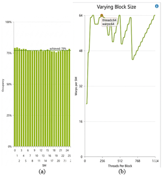
Figure 4 are extracted from the Nsight profile report when implementing the parallel triangulation on 0.131072 million points ($2^{17}$) the kernel launches 512 blocks of 256 threads for each. Figure 4(a) shows the effect of block size on theoretical active warps, the red circle highlights the selected block size (16 × 16 threads) and its corresponding upper limit of active warps, if the chart goes lower than this red circle point, it indicates that the selected configuration is not suitable (reaching 512 threads), suggesting that increasing the block size leads to improved performance. This increasing could subsequently affect the active warp on each SM which in turn improves the occupancy and overall performance.
Figure 4. Parallel performance for 0.1 million points using 16 × 16 threads (a) effect of varying block size on warps per (Streaming Multiprocessor) SM (b) the achieved occupancy
The following equation describes the achieved occupancy:
achieved occupancy $=\frac{\text { active warps }}{\text { maximum active warps }}$ (6)
Figure 4(b) shows a snapshot of the achieved occupancy for each SM, where the RTX3060 contains 38 SMs with each one 128 SPs (Stream Processors) i.e., 4864 cores [34]. The values reported are the average across all warp schedulers for the duration of the kernel execution. The line across these bars is about 79% as the average, this indicates that the chosen block size provided a better balance between threads and available hardware resources, allowing more active warps to reside on each SM and offering a more efficient utilization of the GPU compared to the alternative block size settings.
Figure 5 illustrates an additional plot comparison from multiple experiments that justify the chosen configuration. As data size increases, more thread blocks are launched so, the SM utilization improved and the occupancy increased until saturation occurs. However, very small block sizes (e.g., 8 × 8) reduce warp efficiency, while very large block sizes (e.g., 32 × 32) increase register and shared memory usage per block, that limits the number of active blocks per SM. Therefore, the block sizes (16 × 16) usually achieve the best balance and highest occupancy.
Figure 5. Effect of block size and data size on Graphic Processing Unit (GPU) occupancy
5.2 Performance results
To measure the performance of our method, The GPU execution time was measured by (cudaEvent_t) objects while the Chronos library was used for sequential triangulation. We generated meshes from 8192 points to 134 million as synthesis points in addition to the real-world data set.
In our experiments, data sets were generated by two distribution methods since it directly affects the overall progression of the triangulation process. Firstly, the points are randomly placed according to a uniform distribution, by which we can evaluate the performance under well-distributed condition, focusing on the algorithmic efficiency rather than complex configuration.
To verify the accuracy of our method, we compared the resulting triangulation and execution times with those of the most popular available algorithm, CGAL library in addition to a sequential algorithm that we programmed. For different numbers of input points, the running time increases linearly with the data sizes. Based on our experimental results, we report speedups, our approach achieves ×3 to ×13 times over CGAL as depicted in Table 3, the computation times was recorded after 5 trials as average on GPUs.
Table 3. Performance of the proposed parallel DT over sequential methods
|
# of Points |
Execution Time (m sec) |
Speedup/CGAL |
||
|
Sequential |
CGAL |
Proposed cuDT |
||
|
8,192 |
3.25 |
0.9 |
0.26 |
×3 |
|
65,536 |
4.62 |
1.42 |
0.32 |
×4 |
|
524,288 |
16.57 |
3.89 |
0.73 |
×5 |
|
1,048,576 |
30.19 |
8.14 |
1.10 |
×7 |
|
2,097,152 |
42.61 |
26.24 |
2.91 |
×9 |
|
4,194,304 |
135.19 |
99.56 |
9.84 |
×10 |
|
8,388,608 |
296.37 |
191.72 |
18.37 |
×10 |
|
16,777,216 |
781.25 |
326.86 |
26.31 |
×12 |
|
33,554,432 |
---- |
457.17 |
35.15 |
×13 |
|
67,108,864 |
---- |
---- |
40.32 |
---- |
|
134,217,728 |
---- |
---- |
49.41 |
---- |
As can be seen from the table, the computation time depends on the data size and the speedup increases with it, as larger point sets better exploit massive parallelism. We compute the speedup in compared to CGAL that indeed was faster than our sequential DT due to its optimized structures and advanced memory management, however, for this distribution, a max speedup of ×13 is obtained in compared to the CGAL method.
Also, the sequential algorithm could not be able to process large points (~20M points) and the CGAL could, to about ~35M points and failed for larger data set, while the cuDT can triangulate more than 67 million points.
For small datasets, the performance of our design is lower compared to testing large points, this is due to reasons, the first is general according to overhead and memory transfer costs, and the second concerned with the algorithm itself, where at the beginning of the triangulation, high contention occurs due to few produced triangles leading to longer waiting times, as more points are added, the triangulation grows and the contention decreases due to limited mesh size, improving parallel efficiency of the algorithm.
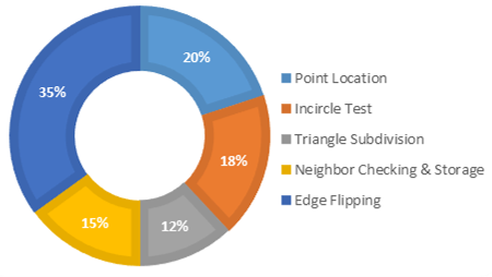
Figure 6. A detailed breakdown of the execution time of our method per thread for uniform data set distribution without stabilized flipping
The second distribution data set is used to highlight the impact of the stabilized flipping method that is more evident for more complex data (non-uniformly distributed). This flipping process is the most time-consuming about (35%) of the overall triangulation process as can be seen from Figure 6, this is in addition to a part of the percentage of neighbour checking and storing that is also triggered after each flipping. For this reason, the stabilized method is designed and employed.
The non-uniformly distributed data is generated so that it has more complex geometry using a perturbed grid distribution, where four or more points are distributed among the circle of a center c(x,y) and a radius r using uniform angular step as in the equations:
$x_i=x_c+r \cos \theta_i$ (7)
$y_i=y_c+r \sin \theta_i$ (8)
where, $\theta_i=\frac{2 \pi i}{k}, i=0$ to $(k-1)$.
Then, the points are displaced by a small uniform random offset ($\delta_x, \delta_y$) is applied to each point, where $\delta \in[-\epsilon, \epsilon]$, this distribution increases the probability violate the Delaunay property, which in turn raises the chance of repeated edge flips allowing a clearer assessment of the stabilization mechanism introduced in Algorithm 4.
The triangulation time of this data set is shown in Figure 7 as compared to the previous distribution, where the design maintains better performance despite of the complexity of data sets, which demonstrate the strength of our design especially for large points. This is due to the fact that the method reduces the oscillation flipping that slows down the triangulation as these few edges have a little impact on the output triangles compared to the time that they consume, especially for very small epsilon value $\epsilon$ = 10-4 that we set, indicating the closeness of the point to the incircle. Therefore, a low percentage of violated edges are not visually noticeable in the output triangles. More details about the stabilized method and its effectiveness are presented in the subsequent section.
Figure 7. Execution time comparison for different distribution data set
5.3 Visualization results
To visualize the resulting mesh and enable detailed observation of the local triangulation behavior during intermediate processing stages, a small data size is used, showing a clear snapshot of the output triangles at different execution stages over time.
Figure 8 illustrates this progressive evolution of the proposed conflict-aware cuDT using 211 randomly distributed points. An early local processing snapshot is shown in Figure 8(a), where only small regions are triangulated. Figure 8(b) and (c) demonstrate the gradual increase in mesh coverage and stabilization of parallel regions over time. Finally, Figure 8(d) presents the complete triangles mesh after all local kernel are completed and globally stabilized.
Figure 8. Progressive visualization of triangulating 2048 random points (16 × 16 threads)
By this visualization, different regions progressing can be observed at different rates depending on workload distribution and local conflict conditions. Also, some non-Delaunay triangles can be seen in these post stages, these temporary configurations are successively corrected through subsequent legalization steps over time until the final stage achieves a complete triangular mesh.
Additionally, regarding the number of triangles that we displayed on the shots (as 4263 in (c)), it can be observed that this number may exceed the final triangle count, since the visualization includes all temporarily generated local triangles during parallel processing, including intermediate non-Delaunay and later-flipped triangles that are subsequently modified or removed during the final stabilization stages.
5.4 Effect of stabilized flipping method
The number of flipped edge is measured in this test, as it directly affects the total execution time in the parallel implementation, since each flip involves atomic processes and neighbourhood updating. Therefore, we measure the total number of flips per edge for the two input sets that were synthesized before with different sizes to quantify the improvement.
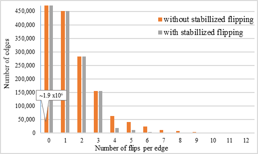
Figure 9. Edge flip distribution for 0.1 million points uniform distribution (edges ≈ 0.3 million, R = 3 and ε = 10⁻⁴)
Figure 9 shows the distribution of all edge flips when triangulating random 0.1 million points that are uniformly distributed (the set produces approximately one-third million edges). It is evident that nearly 78% (0.235/0.3) of the edges already satisfy the Delaunay condition and do not require flipping, while only 1.7% require more than three flips, forming a long tail in the edge distribution as evident in the figure. Although this percentage is small, it is time consuming for redundant computations due to the repeated flips updates.
After enabling Algorithm 4, we set the number of repeated flip R = 3. This tail is significantly reduced using the stabilized method and the distribution becomes more concentrated around low flip counts (0–3), so, the algorithm limits the excessive re-flipping and accordingly the oscillation and total iterations leading to improved overall performance. The improvement for this data set type was about 66% according to the equation:
$\%$ oscillation reduction percentage $=\frac{E-E_{\text {proposed }}}{E} * 100$ (9)
where,
E: the number of flipped edges more than R without stabilized method.
$E_{\text {proposed }}$: the number of flipped edges more than R using stabilized method.
Figure 10 shows the edge flipping count distribution of triangulating one million points that non uniformly distributed. From the approximately three millions edges, we note that the total candidate edge flips increased to 35% (65% no flipped edges) comparing to the previous distribution, and the flips tail got longer (12 times) without stabilized method, whereas the effectiveness of the method significantly decreases these frequent flips to (8 times only), which reduced redundant flips to 74% according to Eq. (9), where the flip-count decrease to 38,961 from 151,782 using this method for those flipped edges more than (R = 3).
Figure 10. Edge flip distribution for 1 million points of non-uniform distribution (edges ≈ 3 million, R = 3 and ε = 10⁻⁴)
This improvement is attributed to eliminating the worklist by removing flip edges that cause repeated process overhead, where it might be possible that the successive rounds of Delaunay and non-optimal flipping might be creating the same edges, resulting in an overhead time where high flip counts translate directly to shorter stabilization time.
Overall, the stabilization method mainly affects the parallel execution efficiency rather than the final triangulation result itself. By limiting the attempts of repeated flip for a single edge, the proposed strategy reduces oscillatory flipping and synchronization overhead between concurrent threads during edge legalization. As shown in Figure 11, where lower repeated flipping activity leads to improved execution time.
Figure 11. Effect of stabilized parameter R on the execution time
The R = 3 value provides a balanced trade-off between stabilization robustness and computational cost during parallel processing. Therefore, the stabilized method reduces the high-frequency flips confirms the effectiveness of the proposed method.
5.5 Real-world data-set test and comparison with previous works
Real-world models are also used as tested data on our cuDT algorithm for visualization, in these models, points are mainly not well distributed, producing complexity and high degeneracy ranges which are important to show the effectiveness of the designed algorithm.
The Stanford Bunny model is a standard model widely used in computer graphics applications, it was selected and triangulated for comparison with [20] to evaluate the output triangles and execution time, while other researches worked on random point-sets. Reconstructing these models, can be implemented by first projecting the points on the xy plane, and then applying the (cuDT) of such points on the plane. Figure 12 shows the triangulation results with different resolutions (477, 1925 and 8431 points).
Clearly, even with this degeneracy of points distribution, the design can handle them with ease, also we can see that the triangles in Figure 12(b) are slightly different from those in that work [20] due to the algorithm used where the order of point insertion and handling the multi-flipping cases. Even so, they validate the Delaunay property, while only 3 among 945 triangles (in this case) are eliminated from the edge flip worklist, which were responsible for resolve synchronization flipping. In general, the error rate was less than 0.3% different triangles for all experiments.
Figure 12. The output triangles of our method on Stanford Bunny with different resolutions
Table 4 reports the performance comparison of the current work with that used the real-world model as well as with others that used random point sets, where the same data size was used for comparison. However, most of the previous works only achieve a significant speed-up for uniform distributions of the input points as they are based on a balanced distribution of the points among the nodes or processors.
Table 4. Performance of the proposed cuDT over other works
|
Work |
# of Points |
Exe Time (m sec) |
|
|
Previous Work |
Proposed Work |
||
|
[20] |
477 |
268.55 |
0.87 |
|
[23] |
21,214,412 |
241.301 |
31.26 |
|
[29] |
1M |
3.85 |
2.91 |
Based on our experimental results, the cuDT outperforms the compared methods and achieves faster execution time due to fully-parallelized mechanism. For all these works, the point insertion is inherently one after another and the parallelism restricts only on limited stages as incircle test as in ref. [20] that implements the design on FPGA, while in the study of Song et al. [23], more parallelism is accomplished, but the design is based on dividing data into blocks that are processed simultaneously one after another, additionally, the merge time of the multi node consumes longer time as mentioned in related works. Also, our algorithm achieves better results in compared to the study [29] despite it updated existing triangles rather than triangulated from initial points.
An efficient triangulation method is proposed and implemented using CUDA architecture on the GPU. Unlike other existing methods, our design (cuDT) is inherently based on the parallel point insertion during triangulation workflow that increases the parallelism level but with a careful conflict-handling process, ensuring no two insertions can modify one triangle at a time, many threads can locate new points, create triangles, and apply flipping, if necessary, in concurrent execution.
The experimental results have shown that the obtained speedup was up to ×30 in compared to sequential, and ×13 in compared to CGAL algorithm, also it outperforms other parallel implementations, even for complex data set distribution where about 17% of running time has been reduced significantly, as we have developed a stabilized flipping method that further improved the performance by untangling the triangulation due to the iterative flipping that is likely to occur on complex data set distribution.
Another important strength in our design is the local flipping as a TLP via a shared worklist, ensuring a progressive flipping of the violations edges without requiring a separated global flipping phase as in existing parallel algorithms. Additionally, we have note that the algorithm is considered a memory-bound rather than compute-bound, it restricts to our GPU bandwidth 448 GB/s, however, this is only for large data.
As a limitation of this design, is that for more than 30M points, the triangles have been generated offline and the CUDA-GL interop could not be realized to directly display the results at real time, whereas, for very few points, the performance remains low approaching that of the sequential triangulations because the assigned threads wait for others to unlock their triangles before proceeding, in addition to the fixed overheads as kernel launch and data transfer on GPU.
As future work, an interactive real-time triangulation with a GUI would be interesting to implement, also, we believe our method can be naturally extended to use constrained Delaunay triangulations, utilizing the proposed cuDT algorithm, and subsequently leveraging it for GIS and terrain data.
[1] Gökgöz, T., Hacar, M. (2020). Comparison of two methods for multiresolution terrain modelling in GIS. Geocarto International, 35(12): 13601372. https://doi.org/10.1080/10106049.2019.1573929
[2] Abed, A.T.M.A., Al-Hamadani, A.J., Al-Naser, M.K.M. (2024). Investigating the effects of canard dihedral angle on the wing span loading in a forward-swept wing aircraft at transonic speeds at steady state conditions using computational fluid dynamics. Mathematical Modelling of Engineering Problems, 11(10): 2859-2868. https://doi.org/10.18280/mmep.111029
[3] Li, P.F., Xie, S.D., Xia, H.P., Wang, D.K., Xu, Z.Y. (2023). Advanced analysis of blast pile fragmentation in open-pit mining utilizing 3D point cloud technology. Traitement du Signal, 40(6): 2507-2519. https://doi.org/10.18280/ts.400615
[4] Jasim, F.M., Al-Isawi, M.M.A., Hamad, A.H. (2022). Guidance the wall painting robot based on a vision system. Journal Européen des Systèmes Automatisés, 55(6): 793-802. https://doi.org/10.18280/jesa.550612
[5] Alrawy, S.N., Ali, F.H. (2020). Voxelization parallelism using CUDA architecture. Al-Rafidain Engineering Journal (AREJ), 25(1): 1-11. https://doi.org/10.33899/rengj.2020.126643.1015
[6] Ferguson, R.S. (2013). Practical Algorithms for 3D Computer Graphics. A K Peters/CRC Press. https://doi.org/10.1201/b16333
[7] Toth, C.D., O'Rourke, J., Goodman, J.E. (2017). Handbook of Discrete and Computational Geometry. 3rd ed. Chapman and Hall/CRC Press. https://doi.org/10.1201/9781315119601
[8] Nawfal, S., Ali, F. (2018). The acceleration of 3D graphics transformations based on CUDA. Journal of Engineering, Design and Technology, 16(6): 925-937. https://doi.org/10.1108/JEDT-04-2018-0072
[9] Eder, G., Held, M., Palfrader, P. (2018). Parallelized ear clipping for the triangulation and constrained Delaunay triangulation of polygons. Computational Geometry, 73: 15-23. https://doi.org/10.1016/j.comgeo.2018.01.004
[10] Bowyer, A. (1981). Computing Dirichlet tessellations. The Computer Journal, 24(2): 162-166. https://doi.org/10.1093/comjnl/24.2.162
[11] Wang, J.C., Cui, C., Gao, J. (2012). An efficient algorithm for clipping operation based on trapezoidal meshes and sweep-line technique. Advances in Engineering Software, 47(1): 72-79. https://doi.org/10.1016/j.advengsoft.2011.12.003
[12] Yonghe, L., Jinming, F., Yuehong, S. (2013). A simple sweep-line Delaunay triangulation algorithm. Journal of Algorithms and Optimization, 1(1): 30-38. http://paper.academicpub.org/Paper?id=15630.
[13] Shamos, M.I., Hoey, D. (1975). Closest-point problems. In 16th Annual Symposium on Foundations of Computer Science (sfcs 1975), USA, pp. 151-162. https://doi.org/10.1109/SFCS.1975.8
[14] Elshakhs, Y.S., Deliparaschos, K.M., Charalambous, T., Oliva, G., Zolotas, A. (2024). A comprehensive survey on Delaunay triangulation: applications, algorithms, and implementations over CPUs, GPUs, and FPGAs. IEEE Access, 12: 12562-12585. https://doi.org/10.1109/ACCESS.2024.3354709
[15] Fabri, A., Pion, S. (2009). CGAL: The computational geometry algorithms library. In Proceedings of the 17th ACM SIGSPATIAL International Conference on Advances in Geographic Information Systems, Seattle Washington, pp. 538-539. https://doi.org/10.1145/1653771.1653865
[16] The CGAL Project. (2026). CGAL User and Reference Manual, Version 6.1.1. https://www.cgal.org/2026/01/26/cgal611/.
[17] Diazzi, L., Panozzo, D., Vaxman, A., Attene, M. (2023). Constrained Delaunay tetrahedrization: A robust and practical approach. ACM Transactions on Graphics (TOG), 42(6): 1-15. https://doi.org/10.1145/3618352
[18] Moriya, N. (2023). Void shape identification in a 2D point distribution. arXiv preprint arXiv:2312.17533. https://doi.org/10.48550/arXiv.2312.17533
[19] N’guyen, F., Kanit, T., Imad, A. (2025). Unbiased finite element mesh Delaunay constrained triangulation applied to 2D images with high morphological complexity using mathematical morphology tools part 1: Binary images. Computation, 13(2): 52. https://doi.org/10.3390/computation13020052
[20] Kallis, C., Deliparaschos, K.M., Moustris, G.P., Georgiou, A., Charalambous, T. (2017). Incremental 2D Delaunay triangulation core implementation on FPGA for surface reconstruction via high-level synthesis. In 2017 22nd IEEE International Conference on Emerging Technologies and Factory Automation (ETFA), Limassol, Cyprus, pp. 1-4. https://doi.org/10.1109/ETFA.2017.8247736
[21] Nguyen, C.M., Rhodes, P.J. (2020). Delaunay triangulation of large-scale datasets using two-level parallelism. Parallel Computing, 98: 102672. https://doi.org/10.1016/j.parco.2020.102672
[22] Tchantchane, Z., Bey, M., Bouhadja, K., (2025). Parallel computing for 3D Delaunay triangulation of non-uniform cloud points. International Journal of Informatics and Applied Mathematics, 7(2): 71-85. https://izlik.org/JA98HY48JG.
[23] Song, Y., Li, M., Liu, X. (2022). A paralleled Delaunay triangulation algorithm for processing large LiDAR points. ISPRS Annals of the Photogrammetry, Remote Sensing and Spatial Information Sciences, 10: 141-146. https://doi.org/10.5194/isprs-annals-X-3-W1-2022-141-2022
[24] Lin, J.X., Chen, R.Q., Yang, C.C., Shu, Z.G., Wang, C.Y., Lin, Y.H. (2016). Distributed and parallel Delaunay triangulation construction with balanced binary-tree model in cloud. In 2016 15th International Symposium on Parallel and Distributed Computing (ISPDC), Fuzhou, China, pp. 107-113. https://doi.org/10.1109/ISPDC.2016.79
[25] Carter, F., Hitschfeld, N., Navarro, C.A., Soto, R. (2018). GPU parallel simulation algorithm of Brownian particles with excluded volume using Delaunay triangulations. Computer Physics Communications, 229: 148-161. https://doi.org/10.1016/j.cpc.2018.04.006
[26] Ray, N., Sokolov, D., Lefebvre, S., Lévy, B. (2018). Meshless voronoi on the GPU. ACM Transactions on Graphics (TOG), 37(6): 1-12. https://doi.org/10.1145/3272127.3275092
[27] Zahida, T. Bouhadja, K. Azouaoui, O., Ghoualmi-Zine, N. (2023). Enhanced unstructured points cloud subdivision applied for parallel Delaunay triangulation. Cluster Computing, 26: 1877-1889. https://doi.org/10.1007/s10586-022-03699-9
[28] Marvie, J.E., Krivokuća, M., Graziosi, D., (2023). Coding of dynamic 3D meshes. In Immersive Video Technologies, pp. 387-423. https://doi.org/10.1016/B978-0-32-391755-1.00020-1
[29] Porro, H., Crespin, B., Hitschfeld, N., Navarro, C., Carter, F. (2023). Maintaining 2D Delaunay triangulations on the GPU for proximity queries of moving points. In SIAM International Meshing Roundtable Workshop 2023 (SIAM IMR 2023), Amsterdam, Netherlands, pp. 1-6. https://hal.science/hal-04029968v1.
[30] Coll, N., Guerrieri, M. (2017). Parallel constrained Delaunay triangulation on the GPU. International Journal of Geographical Information Science, 31(7): 1467-1484. https://doi.org/10.1080/13658816.2017.1300804
[31] Cao, T.T., Nanjappa, A., Gao, M.C., Tan, T.S. (2015). A GPU accelerated algorithm for 3D Delaunay triangulation. In Proceedings of the 18th meeting of the ACM SIGGRAPH Symposium on Interactive 3D Graphics and Games, San Francisco, California, pp. 47-54. https://doi.org/10.1145/2556700.2556710
[32] Cheng, S.W., Dey, T.K., Shewchuk, J. (2013). Delaunay Mesh Generation. New York: Chapman and Hall/CRC. https://doi.org/10.1201/b12987
[33] Shewchuk, R. (2005). Star splaying: An algorithm for repairing Delaunay triangulations and convex hulls. In Proceedings of the Twenty-First Annual Symposium on Computational Geometry, Pisa, Italy, pp. 237-246. https://doi.org/10.1145/1064092.1064129
[34] NVIDIA. (2026). GeForce RTX 3060 Family. https://www.nvidia.com/en-me/geforce/graphics-cards/30-series/rtx-3060-3060ti/.