Cheknane Abdelmalek* | Kouzi Katia | Houcine Sayaf
© 2026 The authors. This article is published by IIETA and is licensed under the CC BY 4.0 license (http://creativecommons.org/licenses/by/4.0/).
OPEN ACCESS
This paper presents a simulation study of torque ripple minimization for a 60 kW three-phase 24/16 switched reluctance motor (SRM) for electric-vehicle (EV) traction. A discrete-time drive model is built from finite-element-computed flux-linkage and static-torque tables; all reported results come from this model. On the identical machine, a sliding-mode speed controller (SMC) and direct instantaneous torque control (DITC) with two-mode commutation are compared, with firing angles tuned by coordinate descent. The well-tuned SMC leaves the steady-state torque ripple at about 23.6% — confirmed under an identical switching constraint — because the ripple is set by the inner current loop, not the speed law. DITC lowers the ripple to 8.8%, and re-tuning only the outer speed loop cuts the load-step speed excursion forty-fold with the ripple unchanged. A fixed-frequency pulse-width-modulated DITC (PWM-DITC) bounds the device switching frequency, giving 12.3% ripple at a 20 kHz carrier; a torque-sharing-function current controller below 600 rpm completes a speed-scheduled dual-mode drive holding the ripple within about 4–12% from 300 to 2500 rpm at rated load (envelope characterized at 50, 200 and 300 N·m). The drive tracks a representative composite speed–load test profile within 2% in speed. Experimental validation on a test bench is ongoing.
direct instantaneous torque control, electric vehicle, firing-angle optimization, sliding-mode control, switched reluctance motor, torque ripple
The electrification of road transport has intensified the search for traction machines that combine high efficiency, robustness and low cost while avoiding dependence on rare-earth permanent magnets. Permanent-magnet synchronous machines dominate today’s electric-vehicle (EV) powertrains, but the volatile supply and price of rare-earth materials have renewed industrial and academic interest in magnet-free alternatives [1]. Among these, the switched reluctance motor (SRM) is a strong candidate: its rotor carries neither windings nor magnets, the construction is mechanically simple and tolerant of high temperature and high speed, and the machine retains a usable torque–speed envelope even under partial faults [2, 3].
These advantages are offset by one persistent drawback. Torque in an SRM is produced in discrete strokes as successive phases are energized and de-energized, and the doubly salient geometry together with deep magnetic saturation makes the instantaneous torque a strongly nonlinear function of current and rotor position. The result is a pronounced torque ripple that excites stator vibration and radiates acoustic noise [3, 4]. In an EV, where the motor operates continuously across the whole speed–torque plane close to the cabin, this ripple acts as an excitation source for vibration and acoustic noise and is widely regarded as a principal obstacle to the wider adoption of SRMs in passenger vehicles [1]. The present study evaluates no vibro-acoustic indicator — no radial-force harmonics, vibration response or sound-pressure level is computed — and torque ripple is used throughout as the control-level quantity to be minimized; any noise-vibration-harshness benefit is therefore indirect and remains to be demonstrated experimentally.
Torque ripple mitigation strategies fall into two broad families [3, 5]. The first acts on the machine geometry — pole shaping, skewing, rotor-tooth modification, or alternative stator and rotor topologies [1]. These measures are effective but fix the trade-off at the design stage. The second family acts on the drive control and can be tuned in operation; it is the focus of the present work. Control-based methods are usually divided into current-control approaches, in which a reference current profile — frequently generated by a torque-sharing function (TSF) — is tracked by an inner current loop [5, 6], and torque-control approaches, in which the electromagnetic torque is regulated directly [7]. Direct torque control and its instantaneous variant, direct instantaneous torque control (DITC), belong to the second group. DITC, introduced by Inderka and De Doncker [8] and extended to four-quadrant operation in this study [9], estimates the total instantaneous torque from the phase currents and rotor position and forces it to track a demand with a hysteresis torque controller; the commutation between an outgoing and an incoming phase is handled by a dedicated two-mode logic.
DITC has been refined extensively in recent years. Al Quraan and Számel [10] combined two-mode commutation with an adaptive turn-on angle on an 8/6 SRM for EV use; Wu et al. [11] addressed the DC-bus-voltage limitation of conventional DITC by means of a multilevel converter; and Sun et al. [12] reformulated the DITC switching rule to raise the drive efficiency. Sliding-mode control (SMC) has likewise been applied widely to SRM speed and torque regulation [13, 14]: improved sliding-mode controllers have been embedded inside the DITC and direct-torque loops to shorten the response and suppress chattering [15], while two-step and observer-based schemes reduce both torque ripple and vibration [16]. Learning-based torque compensation has also been investigated, using wavelet neural networks [17] and current-reshaping neural networks [18]. Firing-angle and controller-parameter optimization is a complementary lever: metaheuristic tuning of the turn-on/turn-off angles — by genetic algorithms or Harris-Hawks optimization — has been reported to reduce the torque ripple substantially [19, 20]. Across these studies, recent DITC and SMC-based torque-control schemes routinely bring the steady-state torque ripple into the low single-digit range [4, 10, 11].
Closest to the present work are the studies that combine two control principles to cover the speed range. Hamouda et al. [21] proposed a universal torque control that runs DITC below a fixed 2000 rpm boundary and average torque control above it, with a dedicated transition rule; being built on average torque control, however, its high-speed mode no longer regulates the instantaneous torque, and the switching frequency of the hysteresis DITC mode remains load-dependent. A second family embeds a TSF inside the DITC loop to shape the commutation interval, with the switching angles adapted or optimized online, and has been demonstrated in simulation on small 8/6 machines [22, 23]; there the TSF serves as a commutation aid within a single hysteresis controller rather than as a distinct low-speed operating mode. Sliding-mode current tracking has also been combined with advanced TSFs [24]. The present study differs from these works in three respects: the machine is a 60 kW 24/16 traction motor modelled on its finite-element-characterized magnetic maps rather than a laboratory-scale prototype; both operating modes — a TSF current controller at low speed and a pulse-width-modulated DITC (PWM-DITC) above it — run at the same fixed 20 kHz device switching frequency, so the power stage sees one carrier over the whole envelope; and the mode transition itself is quantified, in both directions, together with the load dependence of the optimal switching locus in the torque–speed plane.
Two observations motivate the present study. First, on a high-power traction machine the converter operates close to its voltage and current ceiling for much of the stroke, so the extent to which the torque ripple can be reduced by control — and the means of doing so — is not self-evident. Second, comparisons are usually made between a proposed controller and a single baseline, so the relative contributions of the speed-loop controller, the inner torque loop and the firing angles are difficult to separate.
This paper addresses both points. A complete discrete-time model of a 60 kW three-phase 24/16 SRM, intended for EV traction, is built directly from the machine’s finite-element-computed magnetic tables. On this single, identical drive, a sliding-mode speed controller and DITC with two-mode commutation are implemented and compared, and the firing angles are tuned by a coordinate-descent optimization loop. The specific contributions are: (i) a demonstration that, for this actuator-limited drive, the speed-loop controller is secondary — even a sliding-mode speed controller leaves the steady-state torque ripple unchanged; (ii) a DITC implementation with optimized firing angles that reduces the rated-speed torque ripple to 8.8%, and its fixed-frequency PWM-DITC realization that bounds the device switching frequency; (iii) an evaluation of the drive over a representative composite speed–load test profile, across the torque–speed envelope including low speed and light and high load, and under rotor-inertia mismatch and electrical measurement uncertainty; and (iv) an enhancement of the DITC disturbance rejection obtained by re-tuning only the outer loop, which leaves the torque ripple unchanged because the inner and outer loops are separable. The overall structure of the studied drive is shown in Figure 1.

Figure 1. Direct instantaneous torque control (DITC) structure of the switched reluctance motor (SRM) drive (PI: proportional–integral)
2.1 Machine and drive
The studied machine is a three-phase 24/16 SRM rated at 60 kW, sized for the traction of a passenger electric vehicle. Its rated and circuit parameters are listed in Table 1. The 24-stator/16-rotor pole combination gives a rotor pole pitch of 22.5° mechanical, which the model uses as the periodic base for the rotor angle; the magnetic tables are tabulated over a 45° span of rotor position. Each phase is fed by an asymmetric half-bridge converter from a 500 V DC bus — the standard converter for SRM drives, because it allows each phase to be magnetized, freewheeled or demagnetized independently [1].
Table 1. Switched reluctance motor (SRM) and drive parameters
|
Quantity |
Symbol |
Value |
|
Rated power |
P |
60 kW |
|
Number of phases |
— |
3 |
|
Stator/rotor poles |
— |
24/16 |
|
Rotor pole pitch |
— |
22.5° |
|
DC-bus voltage |
Vdc |
500 V |
|
Phase resistance |
Rs |
0.089 Ω |
|
Rotor inertia |
J |
0.0456 kg·m2 |
|
Viscous friction |
Kf |
1 × 10⁻⁷ N·m·s |
|
Rated load torque |
TL |
200 N·m |
|
Sample time |
Ts |
10 µs |
2.2 Electromagnetic model
The SRM is represented by the standard flux-linkage model. For each phase, the terminal-voltage equation is:
$v=R_s i+\frac{d \psi}{d t}$ (1)
where, v is the phase voltage imposed by the converter, Rs the phase resistance, i the phase current and ψ the flux linkage. The flux linkage is therefore obtained by integration,
$\psi(t)=\int\left(v-R_s i\right) d t$ (2)
The phase current is recovered from the flux linkage and the rotor position θ through the inverse magnetization characteristic,
$i=f_i(\psi, \theta)$ (3)
and the instantaneous electromagnetic torque of the phase from
$T=f_T(i, \theta)$ (4)
The two functions fi and fT of Eqs. (3) and (4) are two-dimensional lookup tables. fT is the static-torque table T(i,θ); fi is obtained by inverting the flux-linkage table ψ(i,θ): for every rotor angle the (current → flux) curve is inverted by cubic-spline interpolation and resampled on a regular flux grid.
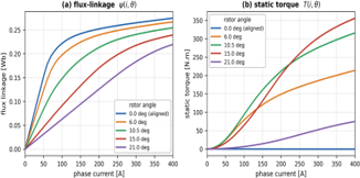
The flux-linkage and static-torque tables were obtained by magnetostatic finite-element characterization of the 24/16 machine in Simcenter Motorsolve (switched-reluctance module): the phase current and the rotor position were swept over the grid below and the flux linkage and static torque computed at each grid point. The material data of the finite-element model are used as supplied, and no thermal dependence of the magnetization data is represented; experimental verification of the tables on the prototype machine is part of the planned hardware phase. The tables span 0–400 A in steps of 10 A (41 current levels) and 0–45° mechanical (two pole pitches) at a nominal resolution of 1.5° (31 rotor positions, with additional support points around the unaligned position at 23.5°), i.e. 41 × 31 points per table. Both tables are evaluated at run time with cubic-spline interpolation inside the tabulated grid. The interpolation error was quantified by leave-one-out cross-validation over the interior current lines of the grid: the reconstruction error does not exceed 0.45% of full scale for the flux-linkage table (0.035% root-mean-square, RMS) and 0.06% of full scale for the static-torque table (0.005% RMS), so the interpolated maps contribute negligibly to the uncertainty of the torque estimator and of the current-reference mapping. Outside the tabulated grid a bounded linear extension of the last tabulated characteristics is used; as shown in Section 2.3, converter overcurrent protection confines the drive to the tabulated region in normal operation, and the reported results are insensitive to the choice of extension (≤0.5 percentage points at the single operating corner where a brief excursion occurs). The magnetic characteristics are shown in Figure 2: the flux linkage saturates strongly near the aligned position, and the static torque is a markedly nonlinear function of both current and position — the very nonlinearity responsible for the torque ripple.
The total electromagnetic torque is the sum of the three phase torques,
$T_e=\sum_{k=1}^3 T_k$ (5)
and the mechanical motion follows
$J \frac{d \omega}{d t}=T_e-T_L-K_f \omega$ (6)
where, J is the rotor inertia, ω the mechanical speed, TL the load torque and Kf the viscous-friction coefficient. The rotor position of each phase is obtained by integrating the speed and reduced modulo the 22.5° pole pitch.
Figure 2. Finite-element-computed flux-linkage and static-torque characteristics of the 24/16 switched reluctance motor (SRM)
2.3 Discrete-time implementation and verification
The complete drive — flux integrators, lookup tables, converter, mechanical equation and controllers — is implemented in discrete time with a forward-Euler scheme at a sample period Ts = 10 μs for the hysteresis controllers and Ts = 1 μs for the fixed-frequency PWM controllers, so that the 20 kHz carrier is resolved. The flux integrator of Eq. (2) is clamped to non-negative values to represent the blocking action of the converter diodes, and a converter overcurrent protection at 400 A — the boundary of the tabulated magnetic map, and a realistic peak-current setting for a 60 kW converter — blocks any positive phase voltage while the phase current is at or above the limit. With this protection active, all steady-state operating points reported in this paper remain inside the tabulated magnetic region; the single exception is the 300 rpm, 200 N·m corner, where the sampled (10 μs) protection allows brief excursions to at most 450 A, about 12% beyond the tabulated current grid. Replacing the linear table extension by a hard saturation-aware clamp at this corner changes the reported ripple by no more than 0.5 percentage points, so the conclusions do not depend on the extrapolation method. The model was verified in three steps. First, a timestep-convergence check: refining the plant integration step from 10 μs to 1 μs while holding the control update at its 100 kHz digital rate changes the steady-state ripple of the hysteresis DITC drive at the rated point by less than 0.3 percentage points (8.8% versus 9.1%), confirming that the reported figures are not integration artefacts. Second, internal consistency: the mean electromagnetic torque matches the applied load torque at every settled operating point, and the phase currents and flux linkages remain within the tabulated maps as stated above. Third, a cross-check against an earlier Simulink reference of the same drive at the matched rated point (200 N·m, 2500 rpm), where the steady-state speed agrees within about 13% (roughly 300 rpm); the residual difference is attributable to the detailed semiconductor and dead-time models of the reference converter versus the idealized switching used here. A systematic multi-point cross-validation of the model over the full operating envelope is ongoing and will accompany the experimental phase of the project. The torque ripple percentages reported in the following sections should therefore be read as model-based predictions whose absolute values may shift on hardware — particularly through dead-time, device on-state voltage drops and finite switching transitions, quantified in Section 5.4 — pending the experimental confirmation that Section 5 identifies as the essential next step.
Two control strategies are implemented on the drive of Section 2. Both share the same commutation principle — each phase conducts within a turn-on/turn-off angular window — but differ in how the converter voltage is determined.
3.1 Sliding-mode speed control
The speed loop is closed by a sliding-mode controller (SMC) acting on the speed error e=N*-N. An integral sliding surface is defined,
$s=e+\lambda \int e d t$ (7)
and the control law, Eq. (8), uses a boundary-layer (saturation) function to limit chattering,
$i^*=K \operatorname{sat}\left(\frac{s}{\phi}\right)$ (8)
where, K is the switching gain, ϕ is the boundary-layer width and λ is the surface coefficient. The current reference i* is applied to whichever phase lies inside its conduction window, and an inner hysteresis comparator switches the asymmetric bridge between +Vdc and -Vdc to keep the phase current within a narrow band around i* — the two-level current-controlled configuration of the original drive model. Inside the boundary layer the sliding-mode law is effectively linear; as shown in Section 4, the steady-state torque ripple of this drive is set by the inner current loop, so even this nonlinear speed controller leaves it essentially unchanged.
3.2 Direct Instantaneous Torque Control
In DITC the speed loop no longer generates a current reference but a total torque demand,
$T^*=K_p e+K_i \int e d t$ (9)
The instantaneous total torque Te is estimated on line from the phase currents and rotor position through the torque table, and the torque error
$\Delta T=T^*-T_e$ (10)
drives the three-level hysteresis controller of Eq. (11), which selects, for each phase, one of three converter states: magnetization (+Vdc), freewheeling (0 V) or demagnetization (-Vdc). The control structure is shown in Figure 1.
The distinctive element of DITC is the commutation logic, which decides how the outgoing and incoming phases share the torque while one is being de-energized and the other energized. A two-mode scheme is used. Each conduction window is divided, by the position within the stroke x, into a build-up zone and a regulation zone. For a phase whose stroke position lies in the build-up zone (x < θb) the phase is an incoming phase: it is magnetized so that its current is established before it is required to produce torque, unless the total torque already exceeds the demand. For a phase in the regulation zone (θb ≤ x ≤ θd) the three-level hysteresis law is applied,
$v=\left\{\begin{array}{cl}+V_{d c}, & \Delta T>+h \\ 0, & -h \leq \Delta T \leq+h, \\ -V_{d c}, & \Delta T<-h,\end{array}\right.$ (11)
where, h is the torque-hysteresis half-band and θd the dwell angle. A phase that has passed its turn-off angle (x > θd) is demagnetized. The total torque is thus regulated collectively: while one phase is still the main torque producer, the next is already building current, and the handover occurs naturally when the leading phase reaches its turn-off angle. This is the digital counterpart of the two-mode commutation reported for EV machines [10, 11]. Because DITC requires the freewheeling state, the asymmetric half-bridge has its two switches controlled independently — a three-level operation, in contrast to the two-level (tied-gate) operation of the SMC current loop.
3.3 Firing-angle optimization
The turn-on and turn-off angles, together with the build-up-zone width θb and the torque-hysteresis band h of Eq. (11), strongly influence both the achievable torque and the residual ripple. They are tuned by a coordinate-descent search that is fully specified as follows, so that the procedure can be reproduced. The cost of a candidate parameter set is the steady-state torque ripple of a 0.32 s DITC simulation at the rated point (2500 rpm, 200 N·m), evaluated over the final 70 ms; a candidate is feasible only if the mean speed over that window exceeds 97% of the reference (an average-torque constraint), and the 400 A converter current limit of Section 2.3 is active throughout, which bounds the RMS and peak phase currents implicitly. The switching frequency is not constrained in this hysteresis-based search; it is bounded separately by the fixed-carrier realization of Section 4.7. The four parameters are swept cyclically in the order θoff→θon→θb→h over the discrete grids θoff∈{13,15,17,19,21,22}°, θon∈{-2,0,1,2,3,4}°, θb∈{1,2,3,4,6}° and h∈{2,4,6,9,13,18} N·m; in each step the value giving the lowest feasible cost is retained while the other three are held fixed, and the cycle repeats until no parameter changes. Started from the neutral point (θon = 0°, θoff = 15°, θb = 1°, h = 6 N·m), the search converges in a single cycle (plus one verification cycle) to turn-on 2°, turn-off 19° and build-up zone 3°, the values used in all subsequent DITC results. The cost is flat to within 0.5 percentage points between the adjacent hysteresis-band values of 9 and 13 N·m; the smaller band, h = 9 N·m, is retained as it bounds the instantaneous torque error more tightly.
All results are obtained with the discrete-time model of Section 2 at a rated load of 200 N·m unless stated otherwise. Torque ripple is quantified by Eq. (12) as the steady-state peak-to-peak torque excursion expressed as a percentage of the mean torque,
$\tau_{\text {ripple }}=\frac{T_{\max }-T_{\min }}{T_{\text {avg }}} \times 100 \%$ (12)
4.1 Machine characteristics
Figure 2 shows the finite-element-computed magnetic characteristics used by the model. The flux-linkage curves exhibit the expected behaviour: near the aligned position the flux linkage saturates strongly above about 100 A, whereas near the unaligned position it remains almost linear. The static torque is strongly nonlinear in current and varies strongly with rotor position: it rises steeply with current, is largest near mid-stroke, and vanishes at the aligned and unaligned positions where the rotor sits in magnetic equilibrium. It is precisely this nonlinearity, combined with the discrete energization of the phases, that produces the torque ripple addressed in the remainder of the paper.
4.2 Controller comparison and torque ripple
The two controllers were run on the identical drive at a speed reference of 2500 rpm with a 200 N·m load. For SMC the firing angles were set to their optimum (turn-on 2.5°, turn-off 14.5°); for DITC the coordinate-descent loop returned the angles given in Section 3.3. The steady-state torque waveforms are compared in Figure 3 and the ripple figures are summarized in Table 2.

Figure 3. Steady-state torque of the sliding-mode control (SMC) and direct instantaneous torque control (DITC) drives (2500 rpm, 200 N·m)
Table 2. Steady-state torque ripple of the sliding-mode control (SMC) and direct instantaneous torque control (DITC) drives (2500 rpm, 200 N·m)
|
Controller |
Torque Ripple |
|
SMC (2-level current hysteresis) |
23.6% |
|
SMC (fixed 20 kHz PWM current loop) |
33.5% |
|
DITC (3-level torque hysteresis) |
8.8% |
The first result concerns the sliding-mode speed controller. Despite its nonlinear law, the SMC leaves the steady-state torque ripple at ≈23.6%. This is not a tuning artefact. With the current-controlled inner loop, the drive operates close to its torque–speed ceiling: during each stroke the hysteresis current loop saturates against the available DC-bus voltage, so the torque waveform is dictated by the machine and the firing angles, not by the speed controller. A more elaborate speed-loop law therefore cannot, by itself, alter the steady-state ripple. The practical implication is important: for this drive the choice of speed-loop controller is secondary, and torque ripple reduction must come from the inner loop.
One could object that this comparison confounds the outer control law with the inner-loop realization: the SMC drive uses a two-level current hysteresis, whereas DITC uses a three-level torque hysteresis with two-mode commutation. To isolate the outer law, a second baseline was therefore simulated in which the SMC speed controller drives a fixed-frequency PWM current-tracking inner loop under exactly the same converter constraint as the PWM-DITC drive of Section 4.7 (20 kHz carrier, 320 A current limit, identical demagnetization logic, the SMC’s own firing angles). Under this matched switching constraint the SMC drive produces 33.5% ripple at the rated point, and between 54% and 58% over the 300–1500 rpm range, versus 7.0–12.3% for PWM-DITC under the identical constraint (Section 4.7). The gap therefore does not originate in the switching realization: a current-reference controller regulates the wrong variable, because at constant current the torque of an SRM still varies strongly with rotor position, whereas DITC regulates the torque itself.
DITC acts exactly there. By regulating the instantaneous total torque directly, DITC reduces the steady-state ripple to 8.8% at the model’s native 100 kHz control rate — an almost threefold improvement over the SMC value — at the same rated operating point. Figure 3 makes the mechanism visible: the SMC torque waveform swings widely between strokes, whereas the DITC waveform is held within a much narrower band around the demand. The residual 8.8% is set by the rate at which the torque-hysteresis loop can act; on a 60 kW drive that rate is bounded by the achievable switching frequency, which motivates the fixed-frequency PWM-DITC realization of Section 4.7.
4.3 Low-speed operation
Torque ripple in an SRM is generally most severe at low speed, an operating region that an EV uses continuously in urban driving and during launch. Figure 4 reports the steady-state ripple of the DITC and SMC drives over the 300–2500 rpm range at a 200 N·m load. Two trends are visible. First, DITC outperforms SMC by a wide margin at every speed, by a factor of about three at rated speed and four to five over the low and mid-range: the SMC ripple stays near 48–50% over most of the range, whereas the DITC ripple lies between 9% and 16%. Second, the DITC ripple itself increases as the speed decreases — from 8.8% at 2500 rpm to 15.9% at 300 rpm. The cause is physical: at low speed the back electromotive force (EMF) is small, so the phase current and hence the torque change very rapidly when a converter state is applied, and the discrete hysteresis controller therefore overshoots its band by more per step. Low-speed operation is consequently the weakest point of hysteresis DITC. It remains markedly better than the SMC baseline, but the result indicates that, for an EV that must deliver smooth torque from standstill, a faster torque loop or a PWM-DITC realization would be needed to keep the low-speed ripple within single digits.

Figure 4. Torque ripple versus speed for direct instantaneous torque control (DITC) and sliding-mode control (SMC) at 200 N·m
4.4 Robustness to inertia mismatch
The effective inertia seen by an EV traction motor varies with vehicle load and driving conditions, so the controller must tolerate a mismatch between the design inertia and the actual one. Figure 5 shows the enhanced DITC subjected to a four-to-one inertia variation, from one-half to twice the nominal rotor inertia, during a start-up followed by a load step from 100 to 250 N·m. The speed response remains stable and free of overshoot for every inertia: a lighter rotor simply accelerates faster and a heavier one slower, as the physics dictates, and the load disturbance is rejected cleanly in all cases. The steady-state torque ripple, shown in the lower panel, stays between 7.4% and 8.6% across the whole inertia range — a spread of barely one percentage point. This weak sensitivity is a direct consequence of the control structure: the torque ripple is set by the inner torque-hysteresis loop, which acts on electrical quantities and does not see the rotor inertia, while the inertia affects only the outer speed loop. It should be noted that this result concerns the steady-state electromagnetic torque ripple of the simulated drive over the tested 0.5–2.0 times inertia range only; it is not claimed to extend to all EV drivetrain conditions, where compliant couplings, gear backlash and load-side dynamics may interact with the drive in ways the present rigid single-inertia model does not represent.

Figure 5. Robustness of the direct instantaneous torque control (DITC) drive to rotor-inertia mismatch over the tested 0.5–2.0 × range
4.5 Speed-loop enhancement
The separability of the inner torque loop and the outer speed loop, already invoked in Section 4.4, can be exploited deliberately to improve the speed-loop dynamics without any penalty on torque ripple. The property is demonstrated here with a load-step test at speed, a disturbance the drive experiences continuously in traction (gradients, road irregularities): with the drive settled at 2000 rpm and 200 N·m, the load torque is stepped to 300 N·m. In the initial DITC implementation the outer speed loop carried untuned gains (Kp = 2, Ki = 60); re-tuning them to Kp = 6, Ki = 40 — values giving a well-damped closed speed loop — produces the comparison of Figure 6 and Table 3. With the original gains the speed dips by 43.8 rpm and re-enters the ±1% band only after 34 ms; with the re-tuned gains the dip is below 1 rpm and the speed never leaves the band — a reduction of the disturbance excursion by more than a factor of forty. The lower panel of Figure 6 confirms that the steady-state torque behaviour is untouched: before the step the ripple is 8.4% and 9.4% for the two gain sets, and after the step it is 7.6% and 7.5% respectively — identical within the stroke-to-stroke variation — because the inner torque loop has not been modified. All currents in this test remain within the 400 A converter limit and hence within the tabulated magnetic map.

Figure 6. Direct instantaneous torque control (DITC) outer-loop re-tuning under a 200→300 N·m load step at 2000 rpm
Table 3. Direct instantaneous torque control (DITC) outer-loop re-tuning under a 200→300 N·m load step at 2000 rpm
|
Speed Loop |
Speed Dip |
Recovery (±1%) |
Ripple after Step |
|
Original (Kp = 2, Ki =60) |
43.8 rpm |
34 ms |
7.6% |
|
Enhanced (Kp = 6, Ki = 40) |
0.7 rpm |
stays in band |
7.5% |
This is worth emphasizing as a design guideline. In the original current-controlled drive (Section 4.2), outer-loop tuning was ineffective because the saturated inner loop dominated the response. Under DITC the inner loop tracks the torque demand quickly and accurately, so the outer speed loop sees a clean “torque-in, speed-out” plant and can be tuned aggressively for fast, well-damped disturbance rejection. The speed dynamics and the torque ripple can thus be designed independently — a practical advantage of DITC for an EV drive, where both a responsive pedal feel and low torque ripple are required.
4.6 Representative composite speed–load test profile
To assess the drive under conditions representative of EV operation, the enhanced DITC (Section 4.5) was run through the composite speed–load test profile of Figure 7. The profile is defined manually at the drive level: it is not derived from a vehicle-dynamics model, and no vehicle mass, wheel radius, gear ratio, road slope or aerodynamic-drag parameter is assumed. It should therefore be read as a representative composite test profile that exercises the controller, not as a standardized EV drive cycle. The profile chains the four regimes that a traction drive must handle: a low-speed crawl at 300 rpm, an acceleration to 1500 rpm followed by an urban cruise, a second acceleration to 2200 rpm for highway operation during which the load is stepped from 200 to 300 N·m to represent a gradient or a head-wind, and a deceleration back to 800 rpm. The run is started from an already settled crawl, so that the response shown is free of the start-up transient.

Figure 7. Enhanced direct instantaneous torque control (DITC) over the representative composite speed–load test profile
The three panels report the speed, the torque and the speed-tracking error. The measured speed tracks the reference to within 1.7% in every steady segment (0.2–0.4% at the cruise and highway points, 1.6% at the 300 rpm crawl, where one rpm is already 0.3%) and within about 3.7% momentarily during the reference ramps. The torque panel shows the electromagnetic torque together with the load torque: the electromagnetic torque rises above the load during each acceleration — the net torque needed to accelerate the rotor inertia, peaking at 311 N·m and always within the 400 A converter limit — sits on the load during cruise, follows the 200-to-300 N·m load step without sustained error, and falls below the load during the deceleration. The torque ripple stays at the level established in Section 4.3: 8.2% at the 300 N·m highway segment, 10.8% at the urban cruise, 13.9% at the 800 rpm cruise and 15.6% at the 300 rpm crawl. The drive thus retains accurate speed tracking and tight torque regulation across the complete profile.
4.7 Fixed-frequency pulse-width-modulated direct instantaneous torque control
Hysteresis DITC reduces the rated-speed ripple to 8.8% (Section 4.2), but it does so through a fast torque-hysteresis loop, and on a 60 kW power stage the achievable rate is limited: the insulated-gate devices switch realistically at only 10–20 kHz, and the hysteresis law moreover produces a variable, load-dependent switching frequency that complicates the design of the electromagnetic-interference (EMI) filter and the thermal management. A practical realization must therefore decouple the torque-control action from the switching frequency of the power devices and fix the latter at a value chosen by the designer.
This is achieved by a fixed-frequency PWM-DITC. The torque-hysteresis comparator is replaced by a proportional–integral torque regulator whose output is a duty ratio; the duty is sampled once per carrier period and applied to the regulation phase through a pulse-width modulator running at a fixed carrier frequency fpwm, which becomes the switching frequency of the devices. The incoming phase is excited through the same converter, and a converter current limit of 320 A — a standard hardware protection — bounds the phase current and regularizes the commutation. The scheme is the torque-control counterpart of classical PWM current control [5] and requires no hardware beyond the existing asymmetric half-bridge: it is a firmware-level change to the same drive.
The PWM-DITC controller was implemented in the discrete-time model of Section 3 and first evaluated at the rated point of 2500 rpm and 200 N·m. Table 4 and Figure 8 report the steady-state torque ripple as a function of the fixed carrier frequency. The ripple decreases substantially as the carrier is raised, from 26.7% at 10 kHz to 11.0% at 40 kHz — the trend is clear though not strictly monotonic, with a minor upturn near 25 kHz — and is 12.3% at a practical 20 kHz — about half the 23.6% of the SMC baseline. The essential point is that the carrier frequency is now a free design parameter: the engineer trades switching loss against torque ripple on a known, broadly monotonic curve, instead of accepting the uncontrolled and load-dependent rate of the hysteresis law. With the silicon-carbide devices now common in traction inverters a 30–40 kHz carrier is realistic, placing the ripple at about 11%.

Figure 8. Pulse-width-modulated direct instantaneous torque control (PWM-DITC) torque ripple versus the fixed carrier frequency (2500 rpm, 200 N·m)
Table 4. Pulse-width-modulated direct instantaneous torque control (PWM-DITC) torque ripple versus the fixed carrier frequency (2500 rpm, 200 N·m)
|
PWM Carrier (Switching) Frequency |
Torque Ripple |
|
10 kHz |
26.7% |
|
15 kHz |
18.8% |
|
17.5 kHz |
15.2% |
|
20 kHz |
12.3% |
|
25 kHz |
12.6% |
|
30 kHz |
11.6% |
|
40 kHz |
11.0% |
|
Hysteresis DITC (Ts = 10 μs, 100 kHz update) |
8.8% |
|
SMC baseline |
23.6% |
Note: PWM = pulse-width-modulated, DITC = direct instantaneous torque control, SMC = sliding-mode speed controller.
In summary, the fixed-frequency PWM-DITC offers a practical route to a designer-controlled switching frequency. It is a firmware-level upgrade of the same magnet-free machine and converter, requiring no extra hardware; it fixes the switching frequency at a chosen 10–40 kHz, removing the uncontrolled, load-dependent rate of the hysteresis law; and at a practical 20 kHz it brings the torque ripple to 12.3%, about half the SMC baseline, at the rated operating point. Two points must be stated plainly. First, this 12.3% is obtained with a simple proportional–integral torque regulator; a predictive or deadbeat torque regulator, or a higher silicon-carbide carrier, would lower it further. Second, the present single-duty PWM-DITC has been demonstrated at the rated operating point: holding a low torque ripple across the whole speed range — and in particular at the low speeds where an EV spends much of its time — calls for a dedicated low-speed controller. Section 4.8 develops one, based on a per-phase TSF, and combines it with the present PWM-DITC into a speed-scheduled dual-mode drive. The multilevel-converter route reported to reduce the ripple further [7, 11] remains a subject of future work. All results reported in this section are obtained in simulation and call for experimental confirmation on a high-power SRM test bench.
4.8 Dual-mode operation across the speed range
The low-speed sweep of Figure 4 showed that the torque ripple of hysteresis DITC, although well below the SMC baseline, grows steadily as the speed falls — from 8.8% at 2500 rpm to 15.9% at 300 rpm — and Section 4.7 showed that the fixed-frequency PWM-DITC, while it bounds the switching frequency, leaves a comparable rated-speed ripple. Neither realization is strongest at low speed, which is precisely where an EV operates during launch and urban driving. This motivates a dedicated low-speed controller, combined with the PWM-DITC into a speed-scheduled dual-mode drive.
At low speed the drive uses a TSF current controller, shown together with the dual-mode structure in Figure 9. The outer speed loop produces the same total torque demand T*. A TSF distributes this demand among the three phases: phase k receives a torque reference fk(θ) T*, where the position-dependent share functions fk are cosine (raised-sine) profiles with a rise, a flat and a fall region. With the three phases offset by one third of the pole pitch (7.5°) the shares sum to unity at every rotor position, so the phase torques add up to the demand. Each conduction window spans θd = 12° (turn-on 4.5°, turn-off 16.5° measured from the aligned position within the 22.5° stroke); the rise and fall regions span θov = 4.5° each and overlap the adjacent phases, with a 3° flat region in between. The PWM carrier is fixed at fpwm = 20 kHz, and the flux loop uses a feed-forward-plus-proportional gain kψ = 3 × 10⁴ V/Wb. Each per-phase torque reference is converted to a current reference through the inverse of the static-torque table, $i_k^*=T^{-1}\left(f_k T^*, \theta\right)$. Each phase current is then regulated by a fixed-frequency loop: because the phase flux linkage is the integral of (v-Rsi), the controller drives the flux to the reference $\psi\left(i_k^*, \theta\right)$ with a feed-forward-plus-proportional law, and a pulse-width modulator running at a fixed carrier applies the converter voltage. Each phase therefore follows a smooth current reference at a designer-chosen switching frequency.

TSF current control depends on the phase current following its shaped reference. At low speed the DC bus has ample voltage headroom to do so; as the speed rises, the rotor sweeps the conduction window faster and the finite 500 V bus can no longer force the current along the reference. The TSF controller is therefore effective only at low speed — a known property of current-controlled SRM drives — and is not a full-envelope solution on its own.
The drive consequently operates in two modes, selected by speed (Figure 9). Below a base speed of 600 rpm the TSF-PWM current controller is active; above it the fixed-frequency PWM-DITC of Section 4.7 takes over. Both modes run at a 20 kHz switching frequency. Figure 10 reports the resulting steady-state torque ripple across the 300–2500 rpm range, against hysteresis DITC alone. At the rated 200 N·m load the TSF controller holds the ripple between 4.2% at 300 rpm and 9.9% at 600 rpm — at 300 rpm nearly a four-fold reduction relative to the 15.9% of hysteresis DITC — and above 600 rpm the PWM-DITC keeps the ripple within a 7–12.3% band, so the dual-mode drive holds the torque ripple within roughly 4–12% over the whole speed range at a fixed 20 kHz switching frequency.

Figure 10. Torque ripple of the dual-mode drive across the speed range at three load levels (50, 200 and 300 N·m), 20 kHz switching
To establish the torque–speed envelope rather than a single load line, the sweep was repeated at a high-demand load of 300 N·m and a light load of 50 N·m (Figure 10). At 300 N·m the dual-mode drive performs at least as well as at rated load: the TSF mode delivers 10.0–14.8% over 300–600 rpm and the PWM-DITC 2.7–13.0% over 700–2500 rpm, with the full 300 N·m mean torque delivered at every point within the 320 A limit. At 50 N·m the picture is more nuanced and is reported here deliberately. First, the nominal PWM-DITC configuration cannot regulate this light load at all: its build-up zone applies the full bus voltage unconditionally for 3° every stroke, which alone exceeds a 50 N·m demand, so the build-up gating (already present in the control law as an option) must be enabled below roughly 100 N·m. Second, even with gating enabled, the percentage ripple of the PWM mode grows large at light load — of the order of 90–160% of the 50 N·m mean, corresponding to an absolute peak-to-peak excursion of about 45–80 N·m set by the per-stroke torque granularity of a 60 kW machine — whereas the TSF mode holds 9–16% (an absolute excursion below 8 N·m) and, because the currents are small, remains able to track its shaped references up to about 1000 rpm instead of 600 rpm. The practical conclusion is that the optimal mode boundary is load-dependent: it lies near 600 rpm at rated and high torque, but moves up to roughly 1000 rpm at light load, so a deployed drive should schedule the switching locus in the torque–speed plane rather than on speed alone. The dual-mode structure itself accommodates this directly, since the boundary is a firmware threshold. It does not reach uniformly single-digit ripple: the residual high-speed ripple is set by the 20 kHz switching frequency, and lowering it further without raising that frequency would require the multilevel converter noted above. As with the other results reported here, the dual-mode drive is evaluated in simulation and calls for experimental confirmation.
The mode switch itself is not free of dynamics, and it must be benign in both directions. Figure 11 shows the dual-mode drive crossing the boundary during a slow reference ramp at 200 N·m load, in acceleration and in deceleration. In acceleration the controller switches from TSF to PWM-DITC the first time the speed reaches the upper hysteresis threshold of 620 rpm; the total torque exhibits a single peak of about 284 N·m — an excursion of +84 N·m above the demand — and re-enters the pre-switch ripple band within about 1.3 ms. In deceleration the controller switches back from PWM-DITC to TSF at the lower threshold of 580 rpm; the torque briefly dips by about 102 N·m below the demand and recovers within about 1.8 ms, with no overshoot above the demand. In both directions the transient is contained to a single electrical period, the speed deviation is negligible, and the ±20 rpm hysteresis band prevents mode chattering, since each transient pushes the speed away from the opposite threshold. The transients reflect the change in current shape between the two controllers — the TSF mode tracks shaped current references whereas the PWM-DITC re-seeds its torque regulator at entry — and their magnitude is comparable to one hysteresis-DITC torque excursion at low speed. This handover behavior is taken up in Section 5, where the switched dual-mode is compared with a single-controller architecture that avoids the discrete switch.

Figure 11. Mode-transition transients at 200 N·m: (a) torque-sharing function (TSF) to pulse-width-modulated direct instantaneous torque control (PWM-DITC) at 620 rpm, +84 N·m peak settling in ≈1.3 ms; (b) back to TSF at 580 rpm, −102 N·m dip recovering in ≈1.8 ms
The preceding sections establish the dual-mode strategy in simulation. Translating it into a deployable EV drive raises several practical questions that a control study should address explicitly. This section examines the control architecture best suited to deployment, the power-stage and switching-frequency requirements, the sensing and parameter-robustness issues, and the digital-implementation constraints. Two of these aspects — the sensitivity to rotor-position measurement error and to DC-bus voltage variation — are quantified by simulation; the remainder are assessed against established drive practice.
5.1 Control architecture: Switched dual mode versus single-controller natural transition
Section 4.8 realized the dual mode as an explicit switch between two distinct controllers selected by speed. This is functionally effective; the cost is two complete control laws, two sets of tuned parameters, and the handover transients quantified in Figure 11 — a single +84 N·m peak settling within about 1.3 ms in acceleration, and a -102 N·m dip recovering within about 1.8 ms in deceleration.
An alternative architecture avoids the switch. The torque-sharing-function current controller and single-pulse operation are not different algorithms but the same current controller in two operating regimes, so the high-speed regime can be reached by a natural transition rather than a discrete switch: as the speed rises and the back-EMF approaches the available DC-bus voltage the current loop progressively saturates, and advancing the turn-on angle then lets each phase slide continuously into single-pulse operation. The torque reference is unchanged throughout; only the achievable current — and hence the torque ripple — changes as the voltage ceiling is reached. This single-controller drive, sketched in Figure 12, uses one control law, one parameter set and a transition intrinsic to the machine physics. The penalty of operating the torque-sharing-function controller alone across the speed range is quantified in Table 5, and Table 6 contrasts the two architectures.

Figure 12. Practical realization of the drive with a silicon-carbide (SiC) converter and a field-programmable gate array (FPGA) or digital signal processor (DSP) controller
Table 5. Torque ripple of the torque-sharing-function (TSF) controller operated alone across the speed range (200 N·m, 20 kHz)
|
Speed |
TSF-Only Ripple |
|
300 rpm |
4.2% |
|
600 rpm |
9.9% |
|
1000 rpm |
41.1% |
|
1500 rpm |
95.3% |
|
2000 rpm |
113.9% |
|
2500 rpm |
112.1% |
Table 6. Comparison of the switched dual-mode and single-controller architectures
|
Criterion |
Switched Dual Mode (TSF + PWM-DITC) |
Single Controller (TSF, Natural Single-Pulse Transition) |
|
Control laws |
Two distinct laws, selected by speed |
One law across the whole range |
|
Tuned parameter sets |
Two |
One; additional speed-scheduled firing-angle law required for the natural transition |
|
Mode transition |
Discrete speed-scheduled switch |
Intrinsic: the current loop saturates and slides into single-pulse operation |
|
Handover torque transient |
+84 N·m peak (≈1.3 ms) in acceleration; -102 N·m dip (≈1.8 ms) in deceleration (Figure 11) |
None; the transition is continuous |
|
Low-speed torque ripple |
≈4–10% (TSF mode) |
≈4–10% (same TSF mode) |
|
High-speed torque ripple |
≈7–13% (regulated PWM-DITC, rated load) |
With fixed firing angles, ≥41% at 1000 rpm and >95% above 1500 rpm (Table 5); requires a firing-angle schedule for practical high-speed operation |
|
Switching frequency |
Fixed (20 kHz) in both modes |
Fixed in the PWM regime; single-pulse at high speed |
|
Implementation complexity |
Higher (two laws, transition logic) |
Lower control-law complexity, but a speed-scheduled firing-angle law must be designed |
|
Status in this paper |
Simulation-validated across 300–2500 rpm (Sections 4.8 and 4.7) |
Conceptual; the firing-angle schedule and full-envelope evaluation are identified as future work |
Note: TSF = torque-sharing function, PWM-DITC = pulse-width-modulated direct instantaneous torque control.
To make the comparison concrete, the TSF current controller of Section 4.8 was simulated alone across the full speed range, with its firing angles held at the low-speed optimum (4.5°/16.5°). The resulting steady-state ripple is reported in Table 5. Below 600 rpm the TSF gives the same low ripple as in the dual-mode realization (4.2%–9.9%). Above 600 rpm the controller becomes voltage-limited: it cannot force the phase current along the shaped reference within the available stroke, the achieved torque drops below the demand for part of each stroke, and the ripple rises to 41.1% at 1000 rpm and to over 95% above 1500 rpm. A deployable single-controller drive therefore requires the firing angles themselves to be scheduled with speed — advancing the turn-on and eventually selecting single-pulse operation as the back-EMF approaches the DC-bus voltage. That firing-angle schedule constitutes its own design problem and is beyond the scope of the present study.
The simulation-validated architecture in this study is therefore the switched dual mode, which delivers the 4–12% ripple of Figure 10 across the full 300–2500 rpm range at rated load, at the cost of the handover transient of Figure 11. The single-controller architecture with natural single-pulse transition is an attractive deployment target — one control law, one parameter set, no handover discontinuity — but, on the present model, only after a speed-scheduled firing-angle law is added. The transient itself may also be reduced by replacing the hard speed switch with a short controller blend over a narrow speed window (for example, weighting the TSF and PWM-DITC voltage commands by a smooth function of the speed); this was not simulated here and is identified as future work.
5.2 Power stage and switching frequency
All results in this paper assume a fixed 20 kHz switching frequency. At the 60 kW power level this is not free: switching losses scale with frequency, and silicon IGBTs at this power are typically operated at 8–15 kHz to keep those losses and the junction temperature within bounds. A fixed 20 kHz — and the 30–40 kHz that Table 4 shows would further lower the ripple — is practical with silicon-carbide (SiC) MOSFETs, whose smaller switching energy makes such frequencies routine. The power stage assumed here is therefore a SiC asymmetric half-bridge; with silicon IGBTs the switching frequency would have to be reduced and a higher torque ripple accepted, along the trend already quantified in Table 4. The device technology, not the control law, sets the achievable switching frequency.
To quantify the claim, a first-order loss estimate was computed from the simulated 20 kHz phase-current waveforms at the rated point (2500 rpm, 200 N·m, i.e. 52.4 kW of mechanical output), assuming a representative 1200 V/400 A-class SiC MOSFET half-bridge per phase with RDS(on) = 3.2 mΩ at operating temperature, antiparallel SiC Schottky diodes (0.9 V threshold, 2 mΩ slope) and a combined switching energy Eon + Eoff = 14 mJ at the 800 V, 400 A datasheet reference, scaled linearly with the switched voltage and current. Over the simulated steady state each phase leg switches at an effective rate of about 27 kHz (the 20 kHz chop plus the commutation edges) at a mean switched current of about 130 A. The resulting estimate is approximately 610 W of conduction loss (dominated, as expected for an asymmetric half-bridge, by the diode paths of the freewheeling and demagnetization states) and approximately 110 W of switching loss — about 720 W in total, i.e. a converter efficiency near 98.6% at the rated point, with the switching contribution only about one sixth of the total. The 20 kHz carrier is therefore not loss-critical for a SiC power stage. This is a first-order analytical estimate on simulated waveforms, not a measured efficiency; the thermal design (junction temperatures, heat-sinking, and the loss balance over the full torque–speed envelope) is deferred to the hardware phase of the project.
5.3 Sensing and parameter robustness
Both control modes depend on accurate rotor-position information: the TSF, the inverse-torque table, the firing angles and the torque estimate are all functions of position. Figure 13(a) quantifies the effect of a constant rotor-position measurement error and shows that the two modes differ markedly in sensitivity. The TSF mode is tolerant — a ±0.5° error changes its ripple by about one percentage point (from 4.8% to 5.3–5.9% at 400 rpm). PWM-DITC is far more sensitive: a ±0.5° error already raises its ripple from 7.0% to about 12% at 1500 rpm, and a ±2° error drives it to 19–33%, because the error corrupts both the firing angles and the instantaneous-torque estimate. The practical requirement is firm: the drive needs a position transducer accurate to a few tenths of a degree. A resolver or an automotive-grade optical encoder meets this directly; sensorless position estimation is least reliable at low and zero speed — precisely the regime in which the TSF mode operates — so a physical position sensor is the pragmatic choice.
The DC-bus voltage of an electric vehicle varies with the battery state of charge. Figure 13(b) shows this variation to be comparatively benign and, for the PWM-DITC, monotonic: over a 430–560 V range the TSF ripple varies by about one percentage point, while the PWM-DITC ripple improves steadily from 10.6% at 430 V to 3.6% at 560 V as more voltage headroom becomes available for torque forcing. No special compensation for bus-voltage variation is required beyond using the measured bus voltage in the duty calculation.

Figure 13. Torque ripple sensitivity to (a) rotor-position error and (b) DC-bus voltage, for the torque-sharing-function (TSF) and pulse-width-modulated direct instantaneous torque control (PWM-DITC) modes (200 N·m)
A third dependence is on machine parameters. The flux-based current loop uses the phase resistance Rs, and any flux estimator built on the integral of (v-Rsi) is sensitive to it; Rs varies by roughly 40% between cold and hot operation. A deployable implementation therefore needs online Rs adaptation, or a winding-temperature measurement feeding a resistance correction, together with a drift-free (modified) integrator where the flux is estimated rather than measured. The torque and flux look-up tables are likewise affected by temperature and manufacturing tolerance and benefit from periodic recalibration.
5.4 Digital implementation and converter non-idealities
The fixed-frequency PWM-DITC and dual-mode simulations integrate the drive at a 1 μs step to resolve the 20 kHz PWM carrier; the hysteresis-DITC results of Sections 4.2 and 4.3 use the Table 1 native sample period of 10 μs, consistent with the original Simulink model. A production controller does not evaluate its control law at 1 MHz. The speed loop, TSF, table look-ups, flux and torque estimation and the modulator are computed once per switching period — 50 μs at 20 kHz — on a field-programmable gate array (FPGA) or a fast digital signal processor. The duty-cycle update in the present model is already performed once per PWM period, so the model is representative in that respect; the residual quantization is in the rotor position used for the firing decisions, which at 2500 rpm and a 20 kHz update is resolved to about 0.75° — a position uncertainty whose effect is bounded by Figure 13(a). The per-period computational load is within the capability of current automotive-grade FPGAs and DSPs.
Because DITC regulates a torque that is estimated (from the measured currents, the measured position and the static-torque table) rather than measured, its performance also depends on the electrical measurement chain and on the implementation delays. Four such non-idealities were quantified by simulation at the rated PWM-DITC point (2500 rpm, 200 N·m, 20 kHz, nominal ripple 12.3%): additive white current-sensor noise, a systematic scale error of the torque table, converter dead time (modelled as diode freewheeling for the dead-time interval after each commanded transition), and a computation delay of whole duty-update periods. Table 7 reports the results. Two conclusions follow. First, torque-table scale errors and realistic dead times are benign: a ±5% table error or a 2 μs dead time raises the ripple by at most 3 percentage points, and the mean torque is held exactly by the outer speed loop in all cases. Second, the dominant sensitivities are current-sensor noise and control latency: 1% full-scale noise (4 A RMS) roughly doubles the ripple and one 50 μs duty-update delay raises it to about 22%. A deployable PWM-DITC therefore needs a low-noise current-measurement chain (or filtering of the torque estimate) and a control pipeline that computes the duty within the same switching period in which it is applied — both standard requirements, but ones this drive genuinely depends on.
Table 7. Sensitivity of the pulse-width-modulated direct instantaneous torque control (PWM-DITC) drive to measurement and implementation non-idealities
|
Non-Ideality |
Torque Ripple |
|
None (nominal) |
12.3% |
|
Current-sensor noise 0.5% FS (2 A RMS) |
20.1% |
|
Current-sensor noise 1% FS (4 A RMS) |
27.8% |
|
Current-sensor noise 2% FS (8 A RMS) |
40.2% |
|
Torque-table scale error -5% |
13.2% |
|
Torque-table scale error +5% |
14.3% |
|
Dead time 1 μs |
14.2% |
|
Dead time 2 μs |
15.5% |
|
Duty-update delay 50 μs (one period) |
21.7% |
|
Duty-update delay 100 μs (two periods) |
37.7% |
Note: 2500 rpm, 200 N·m, 20 kHz; FS: full scale; RMS: root mean square
Two converter non-idealities must also be compensated. The dead-time inserted between the two devices of each half-bridge leg, and the finite on-state voltage drop of the devices, both distort the volt-seconds actually applied to the winding; left uncompensated, they corrupt the current loop and any flux estimate and partially erode the ripple reduction the control law achieves. Standard dead-time and on-state-drop compensation is therefore required, and the phase-current sensors must have enough bandwidth and low enough noise that they do not themselves limit the torque-estimation accuracy. Table 8 summarizes these requirements.
Table 8. Practical requirements for a hardware realization of the drive
|
Subsystem |
Practical Requirement |
Recommended Solution |
|
Power converter |
20 kHz switching at 60 kW with switching losses and junction temperature within bounds |
SiC asymmetric half-bridge |
|
Position sensing |
Rotor-position accuracy of a few tenths of a degree (Figure 13(a)) |
Resolver or automotive-grade encoder; low-speed sensorless estimation is not adequate |
|
Current sensing |
Bandwidth and noise that do not limit the torque estimate |
Automotive-grade closed-loop current sensors |
|
Digital platform |
Complete control law evaluated within the 50 μs PWM period |
FPGA or fast DSP |
|
Parameter robustness |
Rs drift (≈40% cold-to-hot); look-up-table drift with temperature and tolerance |
Winding-temperature or online Rs compensation; drift-free flux integrator; periodic table recalibration |
|
Converter non-idealities |
Dead-time and device on-state voltage drop distort the applied volt-seconds |
Standard dead-time and on-state-drop compensation |
|
Validation |
Confirm the simulated ripple performance |
Experimental test on a (scaled) SRM bench |
These considerations do not change the control results reported in the preceding sections; they define the conditions under which those results can be reproduced on hardware. None of the requirements is exotic — a SiC asymmetric half-bridge, a resolver, automotive-grade current sensors, an FPGA-class controller and standard parameter and dead-time compensation constitute a conventional high-performance SRM drive — and the essential remaining step, beyond the scope of the present simulation study, is experimental validation on such a platform.
This paper has presented a simulation-based study of torque ripple minimization for a 60 kW three-phase 24/16 SRM intended for EV traction; every result reported here is obtained from a discrete-time simulation model, and no experimental measurement is included. The model of the complete drive was built from the machine’s finite-element-computed magnetic tables, and two control strategies — sliding-mode speed control and DITC with two-mode commutation — were compared on the identical drive, with the firing angles tuned by a coordinate-descent optimization loop.
The main findings are as follows. For this actuator-limited drive the speed-loop controller is secondary: even a well-tuned sliding-mode speed controller leaves the steady-state torque ripple at ≈23.6% — and at 33.5% even under the same fixed-frequency PWM constraint as the proposed drive — because the saturated inner current loop, not the speed law, dictates the torque waveform. Torque ripple reduction must therefore come from the inner loop, and DITC delivers it: regulating the instantaneous total torque directly lowers the ripple to 8.8% at the native control rate at the rated operating point. The DITC drive tracks a representative composite speed–load test profile — crawl, accelerations, highway cruise and a load step — accurately; its torque ripple, while three to five times lower than the SMC baseline over the speed range, deteriorates at low speed, which is identified as the weakest operating point of hysteresis DITC. The steady-state torque ripple is weakly affected by a four-to-one rotor-inertia mismatch in the tested model, indicating that the inner loop is insensitive to this mechanical parameter under the simulated conditions. Finally, because the inner torque loop and the outer speed loop are separable, re-tuning only the speed loop reduced the speed excursion under a rated 200-to-300 N·m load step from 43.8 to below 1 rpm — holding the speed within its ±1% band throughout — with no change in torque ripple.
As a practical realization, Section 4.7 implemented a fixed-frequency PWM-DITC, in which a torque regulator drives a pulse-width modulator at a designer-chosen carrier frequency. At a practical 20 kHz the rated-speed torque ripple is 12.3%, about half the SMC baseline, decreasing to 11.0% at 40 kHz; the switching frequency is thereby fixed by the designer instead of being left to the load-dependent rate of the hysteresis law. To hold a low ripple across the full speed range, and in particular at the low speeds that dominate urban driving, Section 4.8 added a torque-sharing-function current controller for the low-speed regime and combined it with the PWM-DITC into a speed-scheduled dual-mode drive: the TSF controller operates below 600 rpm and the PWM-DITC above it. The dual-mode drive holds the torque ripple within roughly 4–12% across the 300–2500 rpm range at rated load and remains effective at a 300 N·m high-demand load, all at a fixed 20 kHz switching frequency, eliminating the low-speed ripple growth of DITC alone; at light load the optimal mode boundary moves up in speed, so a deployed drive should schedule the mode switch in the torque–speed plane. Section 5 set out the requirements for a hardware realization — a SiC power stage, a position transducer accurate to a fraction of a degree, an FPGA-class digital controller, and standard parameter and dead-time compensation — and identified the single-controller architecture, with a natural transition into single-pulse operation, as the simpler choice for deployment. A multilevel-converter realization, which would lower the residual high-speed ripple without raising the switching frequency, and experimental validation on a high-power SRM test bench are the subjects of future work.
|
e |
speed error, rpm |
|
fi |
inverse magnetization characteristic, A |
|
fk |
torque-sharing function of phase k |
|
fpwm |
pulse-width-modulation carrier frequency, Hz |
|
fT |
static-torque characteristic, N·m |
|
h |
torque-hysteresis half-band, N·m |
|
i, i* |
phase current and its reference, A |
|
J |
rotor inertia, kg·m² |
|
K |
sliding-mode switching gain |
|
Kf |
viscous-friction coefficient, N·m·s |
|
Kp, Ki |
speed-loop proportional and integral gains |
|
kψ |
flux-loop feed-forward-plus-proportional gain |
|
N*, N |
reference and measured speed, rpm |
|
Rs |
phase resistance, Ω |
|
s |
sliding surface |
|
T, Te |
phase and total electromagnetic torque, N·m |
|
T* |
total torque demand, N·m |
|
TL |
load torque, N·m |
|
Ts |
sample period, s |
|
v |
phase voltage, V |
|
Vdc |
DC-bus voltage, V |
|
Greek symbols |
|
|
ΔT |
torque error, N·m |
|
θ |
rotor position, degree |
|
θb |
torque build-up-zone width, degree |
|
θd |
dwell angle, degree |
|
θon, θoff |
turn-on and turn-off angles, degree |
|
θov |
torque-sharing-function overlap angle, degree |
|
λ |
sliding-surface coefficient, 1/s |
|
τripple |
torque ripple, % |
|
ϕ |
boundary-layer width of the sliding surface |
|
ψ |
flux linkage, Wb |
|
ω |
rotor angular speed, rad/s |
|
Subscripts |
|
|
dc |
DC bus |
|
e |
electromagnetic |
|
k |
phase index |
|
L |
load |
|
s |
stator phase; sampling |
[1] Abdel-Aziz, A., Elgenedy, M., Williams, B. (2024). Review of switched reluctance motor converters and torque ripple minimisation techniques for electric vehicle applications. Energies, 17(13): 3263. https://doi.org/10.3390/en17133263
[2] Bostanci, E., Moallem, M., Parsapour, A., Fahimi, B. (2017). Opportunities and challenges of switched reluctance motor drives for electric propulsion: A comparative study. IEEE Transactions on Transportation Electrification, 3(1): 58-75. https://doi.org/10.1109/TTE.2017.2649883
[3] Saleh, A.L., Al-Amyal, F., Számel, L. (2024). Control techniques of switched reluctance motors in electric vehicle applications: A review on torque ripple reduction strategies. AIMS Electronics and Electrical Engineering, 8(1): 104-145. https://doi.org/10.3934/electreng.2024005
[4] Sreeram, K., Preetha, P.K., Rodríguez-García, J., Álvarez-Bel, C. (2025). A comprehensive review of torque and speed control strategies for switched reluctance motor drives. CES Transactions on Electrical Machines and Systems, 9(1): 46-75. https://doi.org/10.30941/CESTEMS.2025.00006
[5] Husain, I. (2002). Minimization of torque ripple in SRM drives. IEEE Transactions on Industrial Electronics, 49(1): 28-39. https://doi.org/10.1109/41.982245
[6] Chai, S., Guo, X., Liu, Z., Zhang, P., Ding, Y., Hua, W. (2025). Torque ripple reduction in switched reluctance machines considering phase torque-generation capability. Electronics, 14(9): 1757. https://doi.org/10.3390/electronics14091757
[7] Cai, J., Dou, X., Cheok, A.D., Yan, Y., Zhang, X. (2025). Overview of the direct torque control strategy in switched reluctance motor drives. IEEE Transactions on Transportation Electrification, 11(1): 1617-1628. https://doi.org/10.1109/TTE.2024.3408647
[8] Inderka, R.B., De Doncker, R.W. (2003). DITC—Direct instantaneous torque control of switched reluctance drives. IEEE Open Journal of Industry Applications, 39(4): 1046. https://doi.org/10.1109/TIA.2003.814578
[9] Fuengwarodsakul, N.H., Menne, M., Inderka, R.B., De Doncker, R.W. (2005). High-dynamic four-quadrant switched reluctance drive based on DITC. IEEE Transactions on Industry Applications, 41(5): 1232-1242. https://doi.org/10.1109/TIA.2005.853381
[10] Al Quraan, L., Számel, L. (2023). Torque ripple reduction of switched reluctance motor using direct instantaneous torque control and adaptive turn-on technique for electric vehicle applications. IET Electric Power Applications, 17(12): 1502-1514. https://doi.org/10.1049/elp2.12358
[11] Wu, Y., Yang, R., Sun, Q., Xu, S., Wang, X. (2023). Direct instantaneous torque control of SRM based on a novel multilevel converter for low torque ripple. World Electric Vehicle Journal, 14(6): 140. https://doi.org/10.3390/wevj14060140
[12] Sun, Q., Wu, J., Gan, C. (2021). Optimized direct instantaneous torque control for SRMs with efficiency improvement. IEEE Transactions on Industrial Electronics, 68(3): 2072-2082. https://doi.org/10.1109/TIE.2020.2975481
[13] Sun, X., Wu, J., Lei, G., Guo, Y., Zhu, J. (2021). Torque ripple reduction of SRM drive using improved direct torque control with sliding-mode controller and observer. IEEE Transactions on Industrial Electronics, 68(10): 9334-9345. https://doi.org/10.1109/TIE.2020.3020026
[14] Sun, X., Xiong, Y., Yang, J., Tian, X. (2023). Torque ripple reduction for a 12/8 switched reluctance motor based on a novel sliding mode control strategy. IEEE Transactions on Transportation Electrification, 9(1): 359-369. https://doi.org/10.1109/TTE.2022.3161078
[15] Wu, J., Wang, H., Li, L., Yang, Y., Guo, Z. (2025). Direct instantaneous torque control strategy for vehicle SRM based on improved convergence-rate sliding-mode control. Scientific Reports, 15: 27130. https://doi.org/10.1038/s41598-025-06550-4
[16] Kimpara, M.L., Reis, R.R., da Silva, L.E.B., Pinto, J.O.P., Fahimi, B. (2022). A two-step control approach for torque ripple and vibration reduction in switched reluctance motor drives. IEEE Access, 10: 82106-82118. https://doi.org/10.1109/ACCESS.2022.3195493
[17] Saleh, A.L., Hamouda, M., Számel, L., Abido, M.A. (2026). Wavelet neural network based reduced-ripple DITC of switched reluctance motors in electric vehicles. Scientific Reports, 16: 15564. https://doi.org/10.1038/s41598-026-46371-7
[18] Jing, B., Liang, G., Dang, X., Jiang, Y. (2025). Reducing torque ripple for switched reluctance motors by current reshaping neural network. Scientific Reports, 15: 17530. https://doi.org/10.1038/s41598-025-02228-z
[19] Reis, R.R.C., Kimpara, M.L.M., Galotto, L., Pinto, J.O.P. (2023). Genetic algorithm-based commutation angle control for torque ripple mitigation in switched reluctance motor drives. IEEE Access, 11: 97331-97339. https://doi.org/10.1109/ACCESS.2023.3313436
[20] Oloo, J., Laszlo, S. (2025). Torque ripple minimization for switched reluctance motor drives based on Harris Hawks–radial basis function approximation. Energies, 18(4): 1006. https://doi.org/10.3390/en18041006
[21] Hamouda, M., Al-Amyal, F., Odinaev, I., Ibrahim, M.N., Számel, L. (2022). A novel universal torque control of switched reluctance motors for electric vehicles. Mathematics, 10(20): 3833. https://doi.org/10.3390/math10203833
[22] Ren, P., Zhu, J., Jing, Z., Guo, Z., Xu, A. (2022). Improved DITC strategy of switched reluctance motor based on adaptive turn-on angle TSF. Energy Reports, 8: 1336-1343. https://doi.org/10.1016/j.egyr.2022.08.076
[23] Wang, H., Wu, J., Xie, C., Guo, Z. (2025). Vehicle-mounted SRM DITC strategy based on optimal switching angle TSF. World Electric Vehicle Journal, 16(1): 26. https://doi.org/10.3390/wevj16010026
[24] Feng, L., Sun, X., Guo, D., Yao, M., Diao, K. (2024). Advanced torque sharing function strategy with sliding mode control for switched reluctance motors. IEEE Transactions on Transportation Electrification, 10: 2302-2311. https://doi.org/10.1109/TTE.2023.3287159