Delu Li*![]() | En Fang
| En Fang![]()
© 2025 The authors. This article is published by IIETA and is licensed under the CC BY 4.0 license (http://creativecommons.org/licenses/by/4.0/).
OPEN ACCESS
This paper presents the design of a novel fishbone-shaped cooling system for silicon carbide (SiC) power modules, based on packaging and thermal analysis of SiC power modules. The overall 3D modeling of the power module and cooling system was carried out using SolidWorks, and cooling performance as well as chip power loss of the novel fishbone-shaped SiC power module was simulated and analyzed using the ANSYS simulation platform. Fluent software was employed to perform fluid-structure interaction (FSI) thermal simulations and parametric analysis of both the novel and traditional cooling systems to evaluate the key thermal performance indicators and enhance the cooling capacity of the power module. Based on a single-factor variable analysis, the effects of various parameters—such as the height of the turbulence column, the inclination angle of the column's cross-section, horizontal spacing, and vertical spacing—on the cooling efficiency were investigated. The structure parameters of the novel fishbone-shaped SiC power module cooling system were further optimized to achieve the optimal cooling performance.
silicon carbide (SiC) power module, cooling system, fishbone-shaped structure, thermal analysis, ANSYS, SolidWorks, Fluent, fluid-structure interaction (FSI), optimization, thermal performance
With the development of new energy electric vehicles, industrial automation, and new types of productive forces, the application fields of power devices have been continuously expanding, and their performance and reliability face higher demands. Experts are dedicated to improving the performance and reliability of power devices by optimizing device structures and cooling solutions, developing efficient cooling solutions through structural modification, reducing conduction resistance, increasing breakdown voltage, and effectively controlling junction temperature, thus improving overall performance and reliability.
In recent years, significant progress has been made by scholars both domestically and internationally in enhancing the performance of cooling systems [1-12], particularly in the field of power module cooling technology for electronic power devices [13, 14]. Grossner et al. [15] investigates the high-temperature characteristics of a half-bridge wire-bondless SiC MOSFET module, indicating that the traditional wire-bond design suffers from large parasitic inductance and inefficient thermal paths, whereas the wire-bondless structure, by directly bonding copper (DBC) substrates to the chip, reduces thermal resistance bottlenecks, maintaining stable electrical performance of the module even at high temperatures (> 200℃). This design optimizes the contact area between the chip and substrate as well as the interface materials (such as solder or sintered silver), effectively improving the heat transfer efficiency from the chip to the heat sink. Seal et al. [16] proposed flip-chip bonding technology, where SiC devices are directly bonded to low-temperature co-fired ceramic (LTCC) substrates, further reducing packaging thermal resistance by shortening the thermal conduction path between the chip and substrate. Prado et al. [17] and Wakamoto et al. [18] emphasizes that high-precision multiphysics modeling of SiC power modules should consider thermal-electrical-mechanical coupling effects. The cooling structure design needs to combine material thermal conductivity (such as SiC chips, AlN substrates), geometric parameters (substrate thickness, heat sink fin dimensions), and boundary conditions (cooling methods) to predict the temperature distribution using finite element simulations, which guides structural optimization. In research on 3.3 kV/450 A SiC MOSFET modules, Watt et al. [19] and Rabkowski et al. [20] experimentally compares the thermal response characteristics of different cooling structures. The results show that using enhanced cooling substrates (such as thick copper layer DBC) and optimized module layouts can reduce the module junction temperature by 15-20℃), validating the effectiveness of structural design in thermal management. Furthermore, high-temperature cycling tests demonstrate that a reasonable cooling structure significantly improves the long-term reliability of the module, reducing packaging failures caused by thermal stress. Kim et al. [21] monitored the thermal resistance changes of silver sintered connections in SiC thermoelectric stack chips in real-time, finding that after 10⁴ power cycles, the thermal resistance increased by only 8%, which verifies its long-term reliability. Grossner et al. [15] and Lukin et al. [22] emphasized that high-precision models must quantify the effect of interface thermal resistance (such as chip-solder-substrate) on temperature distribution. Finite element simulations show that fluctuations in sintered silver interface thermal resistance can cause junction temperature deviations of ±15℃). Prado et al. [17] and Chen et al. [23] compared and found that sintered silver (thermal conductivity > 250 W/(m·K)) has three times better thermal performance than traditional solder (SnAgCu), and the risk of interface cracking in the -50~200℃) cycling test was reduced by 40%. At the system level, Shuai et al. [24] proposed an active thermal management strategy based on junction temperature estimation, adjusting cooling flow in real-time to keep the temperature fluctuation of an 800V electric vehicle SiC module within ±5℃), further enhancing long-term reliability. Lu et al. [13] reviewed that bifurcated and biomimetic tree-shaped microchannels reduced thermal resistance by 18% compared to traditional straight channels, achieving a convective heat transfer coefficient exceeding 50,000 W/(m²·K). Yu et al. [25] further proposed a combined design of microchannels and immersion cooling, achieving junction temperatures below 120℃) at a heat flux density of 200 W/cm². Xu et al. [12] introduced digital twin technology into microchannel optimization, adjusting flow channel sizes and coolant flow rates through real-time simulation, improving the dynamic response speed of the cooling system by 25%, providing new ideas for thermal management under complex conditions.
Despite the progress made in the packaging structure and cooling solutions for SiC devices, existing results are mainly focused on qualitative analysis and experimental verification, and have not yet achieved large-scale application, lacking quantitative research support for specific application scenarios.
This paper focuses on the cooling issues of SiC power modules under high power density. Based on the packaging structure and heat transfer theory of the power module, a novel fishbone-shaped SiC power module cooling system is designed. First, the cooling system of the SiC power module is designed and simulated. The Standard k-ε turbulence model is used to compare the temperature distribution, pressure drop, and flow velocity characteristics of the traditional cooling system, proving that the novel fishbone-shaped SiC power module cooling system outperforms the traditional bifurcated design in cooling efficiency, temperature uniformity, and pressure drop performance. Then, based on a single-factor variable analysis, the effects of parameters such as the height of the turbulence column, the inclination angle of the column's cross-section, horizontal spacing, and vertical spacing on cooling performance are analyzed, and the structure parameters of the novel fishbone-shaped SiC power module cooling system are optimized to form the optimal cooling system.
2.1 Structural comparison
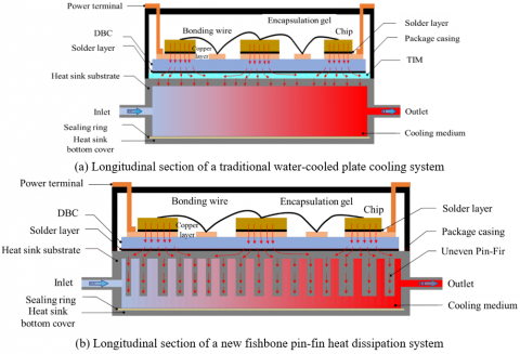
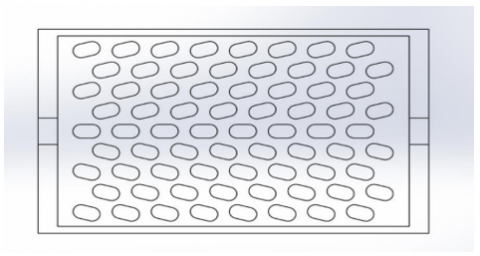
The novel cooling system designed in this paper is compared with the traditional power module cooling system, as shown in Figure 1.
Unlike traditional power module cooling systems, the components involved in the heat transfer path from the upper surface of the chip to the lower surface of the DBC substrate are collectively referred to as the internal structure of the module. The cooling system consists of components such as the cooling substrate, cooling column structure, and cooling bottom cover. These components are integrated into a unified structure through manufacturing processes such as die casting, mold drawing, and welding, and together, they perform the cooling function. This design not only optimizes the thermal conduction path but also improves the overall cooling efficiency and structural stability of the module.
Figure 1. The structure comparison diagram of the new heat dissipation system and the traditional power module heat dissipation system
The cooling system is installed below the power device, and the SiC chip is connected to the insulated ceramic substrate via a solder layer. The sintering process is used for the copper layer of the DBC and the substrate of the cooling system. The DBC substrate, due to its high thermal conductivity and excellent insulation properties, effectively isolates the chip from the heat sink while ensuring efficient heat transfer. To enhance the cooling performance, the cooling substrate adopts a fishbone-shaped structural design to increase the contact area between the coolant and the flow channels, thereby enhancing convective heat transfer efficiency.
2.2 Power module thermal analysis
In the simulation analysis of the traditional SiC power module cooling system, the overall thermal resistance $R_Z$ can be decomposed into four main parts: the chip internal thermal resistance $R_{s l}$, which represents the thermal resistance from the junction to the bottom of the chip; the solder layer thermal resistance $R_{T I M}$, which reflects the thermal conduction performance between the chip and substrate; the substrate thermal resistance $R_{x s}$, including the thermal resistance of the DBC substrate; and the heat sink thermal resistance $R_g$, which represents the thermal resistance from the heat sink to the environment. This decomposition method clearly describes the path of heat transfer from the chip to the cooling medium, providing a theoretical basis for optimizing the cooling design. That is:
$R_Z=R_{T I M}+R_{x s}+R_g+R_{s l}$ (1)
$R_{x s}=\frac{L_{x s}}{K_{x s} S}$ (2)
where, $L_{x s}$ is the distance, $K_{x s}$ is the thermal conductivity (in W/(m∙K)), and $S$ is the heating area (m²).
For the new cooling system, $R_Z$ is expressed by the following formula:
$R_Z=R_{s x}+R_g+R_{s l}$ (3)
Based on heat transfer theory, the junction temperature $T_j$ of each chip during operation is expressed by the following formula:
$T_j=P_1 R_Z+T_l$ (4)
where, $P_1$ is the energy loss of each chip, and $T_l$ is the temperature of the cooling medium in the cooling system. Therefore, the integrated structure design is used to remove the TIM and reduce the overall thermal resistance $R_Z$ of the power module cooling system.
2.3 Power module modeling
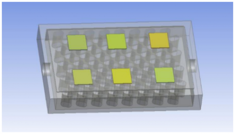
The geometric model of the new vehicle SiC power module cooling system is established, as shown in Figure 2. The 3D model of the power module has structural parameters of 108 mm × 62 mm × 15 mm and consists of six regions of SiC chip sets. The chips are connected by bond wires, and the SiC chip and diode chip are responsible for power conversion and control. These chips are connected to the DBC substrate through wire bonding, while the encapsulation material provides protection and insulation for the internal chips. The chips form an integrated circuit structure, and these components work together to form a complete current loop.
Figure 2. Power module geometry
2.4 Cooling system design
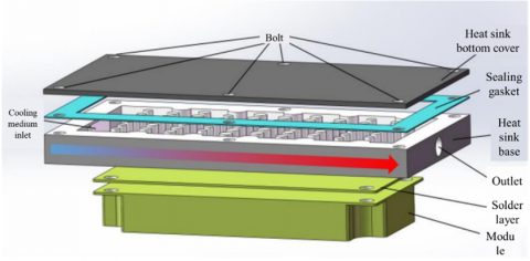
Further design of the 3D model of the cooling system for the module is carried out, where the cooling system mainly consists of the power module, cold plate, and upper and lower connecting bolts. The contact surface between the bottom cover and the cooling substrate is sealed by a gasket, and the bottom cover and gasket are tightly connected by bolts to ensure no leakage of the internal cooling medium during its ingress. The internal turbulence columns are directly integrated into the cooling substrate through machining, which not only makes the internal structure unified but also reduces the thermal resistance of the heat sink contact interface and lowers manufacturing costs, as shown in Figure 3.
Figure 3. Diagram of the heat dissipation system design for SiC power modules
The cooling system model is 3D modeled using SolidWorks software. The model includes six chip sets, a DBC substrate, a cooling base, and coolant flow channels. The dimensions of the chip sets are designed to be 12 × 12 × 0.5 mm. Based on the overall structure data of the module, the modeling dimensions of the cooling cold plate are 108 mm × 58 mm × 14 mm. The coolant flow channel's inlet is designed on the left side, with the outlet on the right, and both the inlet and outlet radii are 4 mm. The materials and their thermal performance parameters used in the SiC power module are listed in Table 1.
A comparative analysis of the traditional bifurcated and new fishbone-shaped cooling systems is carried out. Figure 4(a) shows the cross-section of the traditional bifurcated turbulence column, and Figure 4(b) shows the overall view of the traditional bifurcated fin-like heat dissipation system.
Table 1. Thermal performance parameters of each part material in SiC module
|
No. |
Structural Part |
Material |
Density (kg/m³) |
Specific Heat Capacity (J/kg·K) |
Thermal Conductivity (W/m·K) |
|
1 |
Chip |
SiC |
3210 |
690 |
490 |
|
2 |
Substrate |
DBC |
8978 |
381 |
387.6 |
|
3 |
Packaging Material |
Epoxy Resin |
1200 |
1000 |
0.2 |
|
4 |
Cooling Structure |
Aluminum Alloy |
2700 |
900 |
200 |
|
5 |
Bond Wire |
Aluminum Wire |
2700 |
900 |
237 |
|
6 |
Electrode |
Copper |
8960 |
385 |
401 |
|
7 |
Thermal Interface Material |
Thermal Silicone Grease |
2800 |
1500 |
0.8 |
|
8 |
Solder |
SAC305 |
7400 |
234 |
33 |
|
9 |
Ceramic Layer |
Si3N4 |
3200 |
690 |
90 |
Figure 4. Power module conventional heat sinks
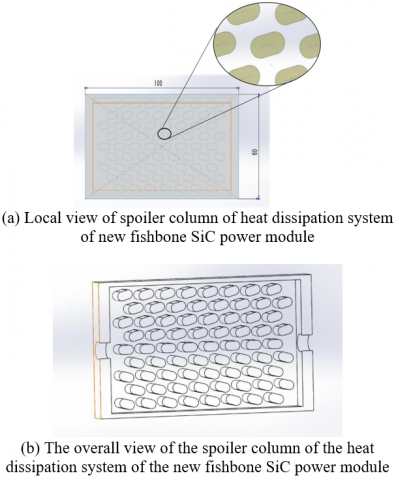
Under the condition that the overall convection heat transfer position parameters of the turbulence column are consistent, the traditional bifurcated circular radius is 2 mm, and the fin-like turbulence column is 10mm long with an adjacent width of 5mm, arranged in a bifurcated distribution inside the cooling system. The length of the turbulence column for the new fishbone-shaped SiC power module cooling system is 10mm, and the adjacent width is 6mm, distributed in the same positions within the cooling system. Figure 5(a) shows a partial view of the turbulence column of the new fishbone-shaped SiC power module cooling system.
Figure 5(a) adopts a single-side direct water-cooling structure. The turbulence columns with a diameter of 4mm are distributed using the bifurcation method, and the fin-like structures are spread throughout the flow channels. Since the coolant flows from left to right, and under the influence of the internal turbulence, while cooling the operating temperature of the power module, there is a phenomenon of excessive temperature difference between the chip inlet and outlet regions.
The new power module optimizes the fishbone-shaped SiC power module cooling system's turbulence column structure to enhance the cooling capacity of the system and reduce the temperature difference within the module. By changing the contact area at the front and rear parts, the temperature uniformity is improved, as shown in Figure 5(b). This design combines a rectangular body and two semicircular ends, providing a larger heat exchange area while significantly improving space utilization and greatly increasing cooling efficiency. Compared with traditional circular fins, the fishbone-shaped structure better adapts to compact design requirements. Its flow channel cross-sectional variation design effectively promotes turbulent flow, enhancing the heat exchange capacity between the coolant and the fin surface, thus further optimizing thermal transfer performance. The fishbone shape improves temperature uniformity, effectively reducing the overall thermal resistance of the cooling system, preventing local overheating, reducing the impact of increasing fluid temperature on cooling performance, and fully reducing the junction temperature difference of the power module.
Figure 5. New fishbone SiC power module heat dissipation system
Figure 6. Layout of baffle columns in a planar arrangement
As shown in Figure 6, the new fishbone-shaped SiC power module cooling system consists of 8 columns of turbulence columns arranged to form the coolant flow and heat transfer channels. The transverse spacing in the length direction of the cooling substrate is set to 5 mm, and the longitudinal spacing in the width direction is set to 6 mm. The turbulence column height is 10 mm. The coolant undergoes forced convection heat exchange within the intercalated column channels formed by circular and rectangular columns. During the flow process, the medium experiences periodic contraction and expansion, causing significant changes in its flow characteristics within the heat dissipation channel. This strong flow transformation significantly enhances the heat exchange efficiency between the cooling base and the coolant, thereby achieving efficient dissipation of heat within the system.
3.1 Mesh division and boundary conditions
3.1.1 Mesh division
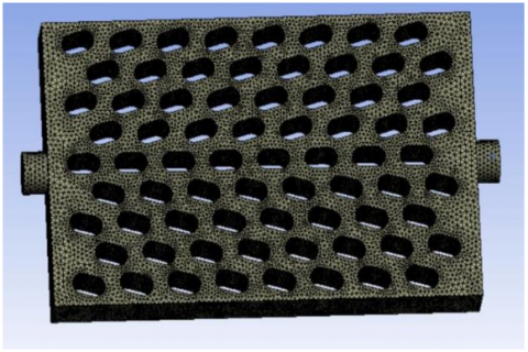
The mesh division adopts an unstructured grid suitable for turbulent flow conditions. The grid size is set to 1 mm, with one boundary layer in the fluid region. The number of cells in each gap is set to 2, and the smoothing factor is selected as medium. Two grid cells are assigned in the thickness direction of the geometric model. Figure 7 shows the grid division of the fluid domain in the cooling system.
Grid refinement is applied to the power chip heating region and the cooling substrate structure, with a refinement size of 0.3 mm. The temperatures at the interfaces are set to be coupled at the interface surface, ensuring that temperature, pressure, and velocity can be correctly transferred and satisfy the continuity conditions. Then, the internal fluid domain structure of the cooling system is expanded with 3 layers, an expansion ratio of 1.2, and a smooth transition expansion type. Finally, the grid is generated with 310,420 nodes and 1,360,752 cells.
Figure 7. Part grid division of fluid domain
3.1.2 Boundary conditions
The heat exchange between the outside air and the outer surface of the power module is modeled as convective heat transfer. The turbulence model is determined as the k-epsilon Realizable model, with the wall function set as scalable, and the energy equation model is used for calculations. The C2-Epsilon is set to 1.9, close to the standard value of the Standard k-ε model, to control the generation and destruction of turbulent dissipation rate; the TKE Prandtl number is set to 1.00, consistent with the standard value, to adjust the diffusion of turbulent kinetic energy; the TDR Prandtl number is set to 1.20, slightly lower than the standard value of 1.3, to optimize the specific flow; both energy and wall turbulent Prandtl numbers are set to 0.85, which is within the conventional range. If the simulation results show anomalies, the TDR Prandtl number or the wall turbulent Prandtl number can be further adjusted to optimize the model performance. The relevant thermal parameters are shown in Table 2.
3.2 Temperature comparison of computational models
Based on the actual power parameters of the power module, the geometric models of the power module and its cooling system were subjected to computational simulations.
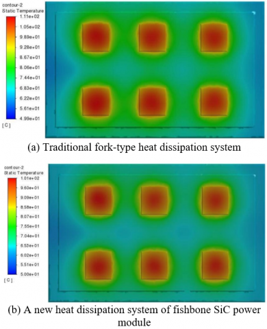
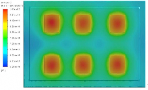
Figure 8 presents a comparison of the temperature distribution cloud maps between the traditional bifurcated and new fishbone-shaped cooling systems. This provides a clear visual representation of the differences in cooling performance between the two designs.
Figure 8. Temperature distribution trapezoidal cloud map of module
The new fishbone-shaped SiC power module cooling system shows significant advantages. The highest junction temperature of the traditional bifurcated cooling system reaches 107.89℃), while the highest junction temperature of the new fishbone-shaped SiC power module cooling system is 100.78℃). The lowest chip temperature of the traditional bifurcated system is 89.25℃), with an average temperature of 98.63℃), and the maximum temperature difference between the chips is 25.05℃). In contrast, the new fishbone-shaped SiC power module cooling system has a lowest chip temperature of 88.93℃), an average temperature of 95.42℃), and a maximum temperature difference of 22.37℃).
The new fishbone-shaped SiC power module cooling system is superior in terms of temperature. The highest junction temperature of the SiC chip is reduced by 7.11℃), the average temperature is reduced by 3.21℃), and the maximum chip temperature difference is reduced by 2.68℃). This design demonstrates a significant advantage in temperature uniformity. By optimizing the diameter and shape of the turbulence columns, the new system can more effectively dissipate heat in the chip heat source area, improving the cooling efficiency. Therefore, the new fishbone-shaped SiC power module cooling system exhibits significant improvements in both cooling performance and temperature control, capable of supporting higher maximum operating power, ensuring the efficient operation of the power module.
Table 2. Thermal parameters for simulation calculations
|
Material |
Structural Parameters (mm) |
Specific Heat Capacity (J/(kg·K)) |
Thermal Conductivity (W/(m·K)) |
Density (kg/m³) |
|
SiC |
10×10×0.5 |
690 |
490 |
3210 |
|
Copper |
30×54×1 |
710 |
150 |
2330 |
|
Aluminum Alloy |
108×28×13 |
880 |
193 |
2800 |
3.3 Pressure drop and vector flow speed comparison of computational models
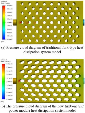
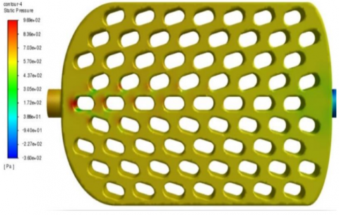
Figure 9 shows the overall pressure distribution of the traditional bifurcated fin-type heat dissipation system and the new fishbone-shaped SiC power module heat dissipation system, highlighting a significant difference between the two systems. In the traditional bifurcated fin-type heat dissipation system, the overall uniform pressure in the fluid domain remains at 785.61 Pa. The inlet pressure is as high as 897.56 Pa, and the outlet pressure drops to 32.59 Pa, resulting in a pressure drop of 764.12 Pa within the cooling medium. In contrast, the new fishbone-shaped SiC power module heat dissipation system shows a distinct advantage in pressure control. The overall uniform pressure in this system is only 638.95 Pa, significantly lower than the traditional system. The inlet pressure is 715.54 Pa, the outlet pressure is 28.75 Pa, and the pressure drop of the cooling medium is 686.79 Pa. Compared to the traditional bifurcated fin-type heat dissipation system, the new fishbone-shaped SiC power module heat dissipation system not only has lower overall uniform pressure but also a reduced pressure drop between the inlet and outlet. This allows the cooling medium to flow with lower pressure loss, reducing energy waste, and offers greater potential for heat dissipation efficiency, effectively achieving heat transfer and cooling functions.
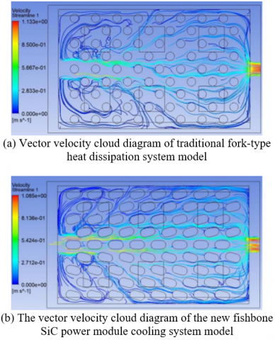
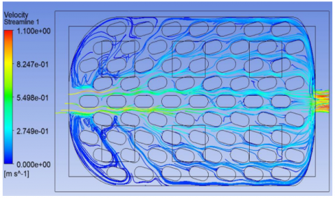
The performance of heat dissipation and temperature uniformity is largely influenced by the velocity vector distribution. Figure 9 shows the vector flow speed distribution in the fluid domain of both heat dissipation system models, revealing the important role of the turbulence columns in the heat dissipation process. Turbulence columns not only significantly increase the heat exchange area between the solid surface of the heat sink and the cooling medium but also effectively disturb the flow state of the cooling medium, thereby enhancing convective heat transfer.
Figure 9. Overall pressure distribution
Figure 10. Vector flow velocity cloud map of the fluid domain
Figure 10 shows that the new fishbone-shaped SiC power module heat dissipation system significantly outperforms the traditional bifurcated heat dissipation system. In terms of flow velocity, the exit flow speed of the cooling medium in the traditional bifurcated heat dissipation system is 0.613 m/s, with an average flow speed of 0.107 m/s in the fluid domain. In contrast, the new fishbone-shaped SiC power module heat dissipation system achieves an exit flow speed of 0.66 m/s, with an average flow speed of 0.118 m/s. In terms of temperature, the exit temperature of the traditional bifurcated heat dissipation system is 68.20℃), while the exit temperature of the new fishbone-shaped SiC power module heat dissipation system is reduced to 67.73℃), showing more uniform heat dissipation.
From the perspective of the internal structure of the heat dissipation system, the interaction between the water flow channel and turbulence columns causes a phenomenon where the cooling medium does not fully cover the flow path in the inlet region. The new fishbone-shaped SiC power module cooling system innovatively adjusts the diameter and shape of the turbulence columns, altering the gap size between the channels. This results in two positive effects: (1) enhancing the instantaneous flow speed variations of the cooling medium, greatly improving the disturbance effect; (2) effectively increasing the convective heat transfer area in the rear part of the power module. These two improvements work synergistically to further enhance the overall heat dissipation efficiency of the system, leading to clear advantages in temperature distribution uniformity and cooling medium flow coverage in the new fishbone-shaped SiC power module cooling system.
3.4 Parameter optimization
The Box-Behnken experimental design method is used to construct a parametric response surface model, with the geometric features of the cooling channel's turbulence structure as design variables. The study investigates the impact mechanism of key parameters such as turbulence column height, lateral spacing, longitudinal spacing, aspect ratio, and tilt angle on heat dissipation performance. The maximum temperature of the power module, the temperature gradient on the chip surface, and the pressure difference at the flow channel inlet and outlet are taken as comprehensive evaluation indicators. Numerical simulations are conducted to analyze the flow and heat transfer characteristics of the cooling medium under different structural parameter combinations.
Compared to the traditional bifurcated fin-type structure, the new fishbone-shaped structure can significantly reduce the maximum junction temperature of the power module and improve temperature uniformity. However, there are flow dead zones in the front half of the heat dissipation system and a medium retention phenomenon in the rear half, which limits further improvements in heat dissipation efficiency. Optimizing the inlet and outlet design of the flow channels can effectively improve the uniformity of the cooling medium flow, reduce dead zones and retention phenomena, and enhance the overall performance of the heat dissipation system.
Based on the optimization improvement of the curved inlet and outlet of the fishbone-shaped SiC power module heat dissipation system, a mathematical model of the power module heat dissipation system is established. The heat dissipation effect is mainly influenced by the structural parameters of the turbulence column in the fishbone-shaped SiC power module heat dissipation system, which are four key factors: turbulence column height (H), fishbone angle (θ), lateral distance (X), and longitudinal distance (Y).
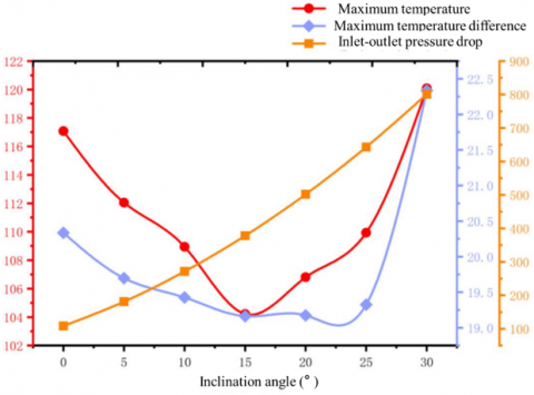
Figure 11. Impact of tilt angle factor
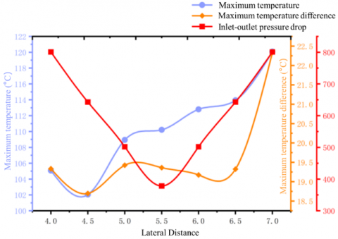
Figure 12. Effect of lateral distance change on temperature
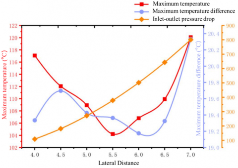
Figure 13. Effect of longitudinal distance change on temperature
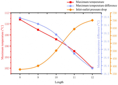
Figures 11 to 14 show the effects of the fishbone angle (θ), lateral distance (X), longitudinal distance (Y), and turbulence column height (H) on heat dissipation performance as single-factor influences. The data show that as the tilt angle increases, the thermal resistance of the heat dissipation system decreases, and both the maximum junction temperature and the chip temperature difference are improved. However, further increases in tilt angle above a critical value of 25° lead to a reduction in cooling channel cross-sectional area, resulting in flow obstruction and a reduction in the heat exchange area between the turbulence structure and the cooling medium. As the lateral distance (X) increases, the maximum junction temperature, temperature gradient, and fluid pressure drop all decrease. However, after reaching a specific value of lateral distance, the improvement in heat dissipation performance levels off. Beyond this critical value, the system's thermal resistance increases, leading to a rise in the maximum junction temperature and temperature gradient, along with a corresponding increase in fluid pressure loss. When the longitudinal distance (Y) increases, the junction temperature peak and temperature gradient of the power device improve. However, when Y ≥ 5.5 mm, the system's thermal resistance increases with the longitudinal distance, resulting in a rise in the power device's temperature extreme values and temperature difference. The height (H) of the turbulence column shows an inverse relationship with system thermal resistance. Given the flow direction of the cooling medium is perpendicular to the axial direction of the turbulence column, the effect of changing H on other parameters is relatively independent.
Figure 14. Impact of vortex generator height factor
Based on the above data analysis, the optimal parameter combination is designed: lateral distance of 5.2 mm, longitudinal distance of 5.8 mm, tilt angle of 14°, and turbulence column height of 10 mm. A 40% volume concentration of ethylene glycol solution is used as the cooling medium, and the flow velocity is set to 0.8 m/s for simulation analysis, as shown in Figures 15 to 17.
The performance results of the heat dissipation system under the optimal design parameters are as follows: the highest temperature of the power module is 98.56℃), the lowest temperature is 87.59℃), the average operating temperature is 94.58℃), and the chip temperature difference is 17.85℃). The fluid domain analysis shows that the average pressure of the heat dissipation system is 629.00 Pa, with inlet and outlet pressures of 901.79 Pa and 245.35 Pa, respectively, resulting in a pressure drop of 656.44 Pa. The average flow velocity of the cooling medium in the flow channel is 0.135 m/s, and the exit velocity is increased to 0.91 m/s, with an exit temperature of 56.00℃).
Compared to the traditional bifurcated fin-type heat dissipation system, the new fishbone-shaped SiC power module heat dissipation system shows significant improvements in key performance indicators: the highest junction temperature is reduced by 8.65%, the temperature difference is reduced by 24.75%, and the pressure drop between the flow channel inlet and outlet is reduced by 12.02%.
Figure 15. Temperature distribution cloud diagram of heat dissipation system
Figure 16. Pressure distribution cloud diagram of heat dissipation system
Figure 17. Velocity streamline diagram of heat dissipation system
This paper presented the design and simulation analysis of a cooling system for SiC power modules. A new fishbone-shaped SiC power module heat dissipation system was proposed. Based on the structural parameters of the new fishbone-shaped SiC power module cooling system, 3D modeling was carried out using SolidWorks, and a comparison of the heat dissipation performance with the traditional bifurcated power module cooling system was made. Through CFD simulations using the Standard k-ε turbulence model, the temperature distribution, pressure drop across the flow channels, and flow velocity characteristics of both cooling systems were analyzed. The results indicate that the new fishbone-shaped SiC power module cooling system outperforms the traditional bifurcated design in terms of heat dissipation efficiency, temperature uniformity, and pressure drop performance. The maximum junction temperature is reduced by 7.11℃), the maximum temperature difference between chips is decreased by 2.68℃), and the cooling medium pressure is reduced by 77.33 Pa.
Based on single-factor variable analysis, the effects of turbulence column height, inclination angle of the turbulence column cross-section, lateral spacing, and vertical spacing on the heat dissipation performance were examined. The optimal structural parameter combination for the cooling system was designed. When the lateral distance of the turbulence column is 5.2 mm, the longitudinal distance is 5.8 mm, and the inclination angle of the turbulence column's circular cross-section is 14°, with a cooling medium consisting of a 40% volume concentration ethylene glycol solution and a flow velocity set at 0.8 m/s, the optimal heat dissipation system was achieved.
[1] Wibowo, S., Arifin, Z., Rachmanto, R.A., Himawanto, D.A., Prasetyo, S.D. (2024). Optimization of photovoltaic performance using a water spray cooling system with different nozzle types. International Journal of Computational Methods and Experimental Measurements, 12(1): 9-19. https://doi.org/10.18280/ijcmem.120102
[2] Patil, G., Tiwari, C., Kavitkar, S., Makwana, R., Mukhopadhyay, R., Aggarwal, S., Betala, N., Sood, R. (2025). Optimising energy efficiency in India: A sustainable energy transition through the adoption of district cooling systems in Pune. Challenges in Sustainability, 13(1): 1-17. https://doi.org/10.56578/cis130101
[3] Pessoa, R.S., Fraga, M.A. (2024). The versatile horizon: SiC power semiconductors in electric vehicles, renewable energy, aeronautics, and space systems. Journal of Aerospace Technology and Management, 16: e3424. https://doi.org/10.1590/jatm.v16.1354
[4] Hassan, A.K., Mohaisen, H.S., Mohammed, K.S., Eleiwi, M.A., Majdi, H.S. (2025). Parametric study of heat transfer in shell and tube heat exchanger: Cooling of engine oil with water and ethylene glycol mixtures. International Journal of Computational Methods and Experimental Measurements, 13(2): 405-426. https://doi.org/10.18280/ijcmem.130217
[5] Hanan, D.F., Lazuardi, G.M., Trisnoaji, Y., Prasetyo, S.D., Mauludin, M.S., Harsito, C., Mahadi, A.A., Arifin, Z. (2024). Thermal and hydrodynamic performance analysis of water-cooled heat sinks using aluminum and structural steel materials. Power Engineering and Engineering Thermophysics, 3(3): 176-188. https://doi.org/10.56578/peet030303
[6] Si, M.T., Zhou, L.P., Peng, W., Zhang, X.Y., Yi, A.L., Wang, C.L., Zhou, H.R., Wang, Z., Ou, X., You, L.X. (2023). Superconducting nanowire single photon detector on 4H-SiC substrates with saturated quantum efficiency. Applied Physics Letters, 123(13): 131106. https://doi.org/10.1063/5.0164368
[7] Damcevska, J., Dimitrijev, S., Haasmann, D., Tanner, P. (2023). The effect of wafer thinning and thermal capacitance on chip temperature of SiC Schottky diodes during surge currents. Scientific Reports, 13(1): 19189. https://doi.org/10.1038/s41598-023-46538-6
[8] Alhialy, N.F. (2024). Dimensioning of a solar adsorption-powered cooling bed for generating relief cooling. International Journal of Heat and Technology, 42(3): 832-850. https://doi.org/10.18280/ijht.420313
[9] Li, J.Y., Poon, A.W. (2024). On-chip passive pump-rejection long-pass filters for integrated SiC-based nonlinear and quantum photonic chips. Optics Letters, 49(2): 411-414. https://doi.org/10.1364/ol.500432
[10] Li, F. (2022). 3-D stacking of SiC integrated circuit chips with gold wire bonded interconnects for long-duration high-temperature applications. IEEE Transactions on Components, Packaging and Manufacturing Technology, 12(10): 1601-1608. https://doi.org/10.1109/tcpmt.2022.3210477
[11] Zhang, Q.H., Yuan, R., Hou, Y.J., Feng, Y.K., Wang, J. (2025). Thermodynamic performance analysis and multi-objective optimization design of cooling systems in wind farms. International Journal of Heat and Technology, 43(3): 969-979. https://doi.org/10.18280/ijht.430315
[12] Xu, Z.M., Xu, J., Guo, Z.C., Wang, H.T., Sun, Z., Mei, X.S. (2022). Design and optimization of a novel microchannel battery thermal management system based on digital twin. Energies, 15(4): 1421. https://doi.org/10.3390/en15041421
[13] Lu, K.J., Wang, C.J., Wang, C.R., Fan, X.L., Qi, F., He, H.D. (2023). Topological structures for microchannel heat sink applications – A review. Manufacturing Review, 10: 2. https://doi.org/10.1051/mfreview/2022035
[14] Zhao, D., Letz, S., Leib, J., Schletz, A. (2023). Influence of SiC chip thickness on the power cycling capability of power electronics assemblies – A comprehensive numerical study. Microelectronics Reliability, 150: 115091. https://doi.org/10.1016/j.microrel.2023.115091
[15] Grossner, U., Kakarla, B., Ziemann, T., Muting, J., Stark, R., Kovacevic-Badstuebner, I. (2017). (Invited) Requirements for highly accurate multiphysics modeling of SiC power MOSFETs and power modules. ECS Meeting Abstracts, MA2017-02(31): 1322-1322. https://doi.org/10.1149/ma2017-02/31/1322
[16] Seal, S., Glover, M.D., Mantooth, H.A. (2017). 3-D wire bondless switching cell using flip-chip-bonded silicon carbide power devices. IEEE transactions on power electronics, 33(10): 8553-8564. https://doi.org/10.1109/tpel.2017.2782226
[17] Prado, E.O., Bolsi, P.C., Sartori, H.C., Pinheiro, J.R. (2022). An overview about Si, superjunction, SiC and GaN power MOSFET technologies in power electronics applications. Energies, 15(14): 5244. https://doi.org/10.3390/en15145244
[18] Wakamoto, K., Ukita, M., Saito, A., Nakahara, K. (2025). Suppression of cohesive cracking mode based on anisotropic porosity in sintered silver die attach encapsulated by epoxy molding compounds. Electronics, 14(16): 3227. https://doi.org/10.3390/electronics14163227
[19] Watt, G., Courtay, A., Romero, A., Burgos, R., Chu, R., Boroyevich, D. (2019). Evaluation of an automated modeling tool applied to new 600 V, 2 A vertical GaN transistors. In 2019 IEEE Applied Power Electronics Conference and Exposition (APEC), Anaheim, CA, USA, pp. 2920-2927. https://doi.org/10.1109/apec.2019.8721880
[20] Rabkowski, J., Sobieski, R., Zdanowski, M., Piasecki, S. (2018). 3.3 kv/450 a SiC mosfet module-modelling and experiments. In 2018 20th European Conference on Power Electronics and Applications (EPE'18 ECCE Europe), Riga, Latvia, pp. P-1.
[21] Kim, D.J., Nagao, S., Chen, C.T., Wakasugi, N., Yamamoto, Y., Suetake, A., Takemasa, T., Sugahara, T., Suganuma, K. (2021). Online thermal resistance and reliability characteristic monitoring of power modules with Ag sinter joining and Pb, Pb-free solders during power cycling test by SiC TEG chip. IEEE Transactions on Power Electronics, 36(5): 4977-4990. https://doi.org/10.1109/tpel.2020.3031670
[22] Lukin, D.M., Dory, C., Guidry, M.A., Yang, K.Y., et al. (2020). 4H-silicon-carbide-on-insulator for integrated quantum and nonlinear photonics. Nature Photonics, 14(5): 330-334. https://doi.org/10.1038/s41566-019-0556-6
[23] Chen, S.T., Lo, P., Hu, C.H. (2024). A hybrid process technology of SiC die separation. Materials and Manufacturing Processes, 39(9): 1277-1289. https://doi.org/10.1080/10426914.2024.2311386
[24] Shuai, Z.B., He, S., Xue, Y.R., Zheng, Y.J., Gai, J.T., Li, Y.H., Li, G.H., Li, J.Q. (2023). Junction temperature estimation of a SiC MOSFET module for 800V high-voltage application in electric vehicles. ETransportation, 16: 100241. https://doi.org/10.1016/j.etran.2023.100241
[25] Yu, Z.Q., Li, M.T., Cao, B.Y. (2024). A comprehensive review on microchannel heat sinks for electronics cooling. International Journal of Extreme Manufacturing, 6: 022005. https://doi.org/10.1088/2631-7990/ad12d4