Vittorio Verda*![]() | Martina Capone
| Martina Capone![]()
© 2025 The authors. This article is published by IIETA and is licensed under the CC BY 4.0 license (http://creativecommons.org/licenses/by/4.0/).
OPEN ACCESS
The Energy Efficiency Directive issued in 2023 forces current district heating (DH) systems to evolve towards 100% heat generation from renewables and waste heat by 2050. To achieve this goal with existing networks, two main issues must be solved: operating temperatures must be lowered, and seasonal energy storage must be integrated. In this work, the integration of groundwater heat pumps in a network is considered in order to provide part of the potential contribution to the renewable share. As the summer thermal demand is much smaller than the winter demand, the excess heat is stored in the saturated ground through heat exchangers that allow one to exchange heat between the return pipes of the network and the groundwater. Heat is then retrieved during the heating season by feeding the heat pumps with groundwater, which is at a temperature larger than the undisturbed water, thus making the heat pumps operate with higher performance. The effect of groundwater flow on the temperature distribution is evaluated in this work by using a proper computational fluid dynamics model of the subsurface, so that the effect on the heat pump efficiency can be properly evaluated.
district heating, groundwater heat pumps, groundwater storage, seasonal storage, temperature reduction
The energy mix currently feeding European District Heating systems is led by fossil fuel, about 51%, while renewables represent about 38% and waste heat about 11% [1]. The Energy Efficiency Directive issued in 2023 has set progressive targets to be achieved in the next few years [2] in order to reach, by 2050, 100% heat generation from a combination of renewables and waste heat. This transition represents a crucial step toward the decarbonization of the heating sector, which accounts for nearly half of the total final energy consumption in Europe [3].
By enabling the integration of multiple low-carbon and renewable heat sources at the urban scale, future renewable district heating systems play a crucial role in this decarbonization context [4]. The main options for integration of renewable energy sources in district heating systems are represented by solar thermal energy [5], geothermal energy [6], heat pumps [7], and biomass. An important contribution is represented by waste heat from data centers [8] waste-to-energy plants, industrial processes, etc. These sources can generally guarantee the coverage of the thermal demand in summer, due to the larger availability of certain resources, such as solar energy, and the small demand. Depending on the size of the heat generation system, an excess production can be registered. The opposite occurs during winter operation. This results in an imbalance between summer surplus and winter demand peaks [9]. To address this challenge, seasonal thermal energy storage (STES) has emerged as a promising solution, enabling the storage of excess heat during periods of low demand and its recovery during colder months [10]. Different STES concepts, such as borehole (BTES) [11], aquifer (ATES) [12], pit (PTES) [13], and tank thermal energy storage (TTES) [14], have been successfully demonstrated across Europe, significantly increasing the renewable share in DH systems [15].
In this work, a specific configuration of aquifer thermal energy storage is analyzed, in which the storage system is coupled with groundwater heat pumps (GWHPs) and integrated into a district heating network. Groundwater represents a reliable and widely available low-temperature energy source, and its use through heat pumps has been increasingly recognized as a promising solution for low-carbon heating and cooling applications [16-18]. In the proposed approach, two different configurations are investigated to exploit the subsurface as a seasonal storage medium, allowing the heat injected during summer to be recovered during the heating season. In winter, the stored heat is extracted by operating the GWHP, which is supplied with groundwater at temperatures higher than the undisturbed level [19]. This increases the coefficient of performance (COP) of the heat pumps and reduces the electricity consumption required for heat generation [20]. In this study, the thermal interaction between the heat exchangers and the aquifer is analyzed by means of a dedicated thermo-fluid dynamic model of the groundwater flow, enabling an accurate evaluation of the heat transfer processes and their influence on the system efficiency.
The DH network considered as a case study for the present analysis supplies heating to more than 6500 buildings, with a peak demand of about 1.5 GW in the mornings and an average thermal load of about 860 GW in typical winter days. The demand is mainly covered using high efficiency combined cycles operating in cogeneration mode and thermal storage units, which are charged at night using the excess heat produced by the combined cycles and discharged during daytime, mainly to cover morning peaks. The district heating network can be schematized as composed of two parts, which are physically interconnected: 1) the transport network, which connects the various areas of the town to the production plants. This is constituted by pipes characterized with large diameters where water flows continuously; 2) various distribution networks, each connecting the transport network to the buildings of a specific area. In the distribution network, the mass flow rate is limited and velocities significantly reduce, especially at night, when the thermal demand of buildings is low or absent.
The water temperature in the transport network is supplied at a temperature of about 120℃ during the heating season, and it is almost constant there, due to the large flowrate. In contrast, water temperature reduces in the distribution networks, especially at night and in mid seasons, due to the small mass flow rates. Due to this behavior, the heat exchangers in the thermal substations are typically oversized. Also, pipe diameters in the distribution networks are oversized. Such features can be used in order to operate the network locally at smaller temperatures by properly adjusting the circulating mass flow rate. In this way, integration of renewables becomes easier.
In the area considered in the present application, the integration of GWHPs constitutes a promising option to significantly increase the share of renewables. The temperature at the thermal substations can be adjusted along the heating season according to the average external temperature, and the desired value can be achieved by mixing hot water coming from the transport network (at about 120℃) and warm water produced by the heat pumps. The cold heat source is constituted by groundwater extracted from the ground and then reinjected. In the area considered here, groundwater is available about 20 m below the surface at an undisturbed temperature of 15℃. Groundwater flows in the ground at about 1.5 m/day.
The distribution network, which is analyzed in the present application, is composed of 3 office buildings. The maximum thermal demand of the three substations is about 860 kW, while the annual thermal energy demand is about 870 MWh.
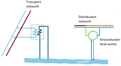
A groundwater heat pump able to produce up to 400 kW of hot water at a maximum temperature of 85℃ is installed in the distribution network, as shown in Figure 1. The connection to the transport network guarantees that the thermal demand is covered even when the demand is larger than 400 KW and the minimum supply temperature exceed 85℃.
As previously discussed, the integration of renewables in district heating networks is easily accompanied by an excess heat generation, which should be properly stored. A possible option is constituted by heat storage in the ground or in the groundwater. In the case examined in the present paper, the main issue is represented by the fact that groundwater flows with a certain velocity. Storage must therefore be operated upstream of the point where heat is then retrieved. Also, it must be specified that, in the case of groundwater storage, water temperature injected in the ground cannot be significantly different than the undisturbed temperature. Typically, the temperature increase can be of the order of 5-7℃ with respect to the unperturbed temperature.
Figure 1. Integration of a groundwater heat pump in the distribution network
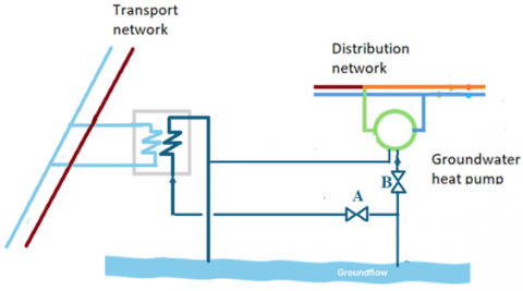
Figure 2. Groundwater storage configuration 1
Figure 2 shows a schematic of a possible system for groundwater storage combined with district heating. In summer operation, the district heating network is also used as a collector of the heat generated by the various renewable/waste heat plants, thus permitting to installation of the storage systems in other positions. Storage can be operated by means of a heat exchanger, which exchanges heat between the return network and the groundwater. The fact that the heat exchanger is fed with water from the return network has two advantages: 1) the excess heat generation can be produced at a lower temperature, thus generally with higher recovery rates and efficiency; 2) water temperature is reduced before being returned to the production plants, therefore heat production efficiency increases.
The cold side of the heat exchanger is fed with groundwater, which is extracted at the undisturbed temperature and reinjected at about 22℃. The mass of warm water travels in the ground; therefore, the position of the heat retrieval should be properly positioned downstream of the injection so that it can be used throughout the heating season.
A second configuration, which uses only two wells, is also considered. A schematic of this configuration is shown in Figure 3. In summer operation, water extracted from the downstream well feeds the heat exchanger connected with the district heating network (valve A is open and valve B is closed) and is then reinjected in the ground through the upstream well. In winter operation, water extracted from the downstream well feeds the heat pump, and it is then re-injected in the ground (valve A is closed and valve B is open). The distance between the two wells should be determined, based on the charging/discharging profiles of the storage system, so that water extracted in summer operation is at the undisturbed temperature, while the maximum amount of warm water is extracted during winter operation. This configuration presents a disadvantage related to the need to install a pipe able to connect the two parts, which limits the sites where this configuration can be applied. The advantage is a reduction in the number of required wells. The effect of the configuration on the storage efficiency is discussed in the following parts.
Figure 3. Groundwater storage configuration 2
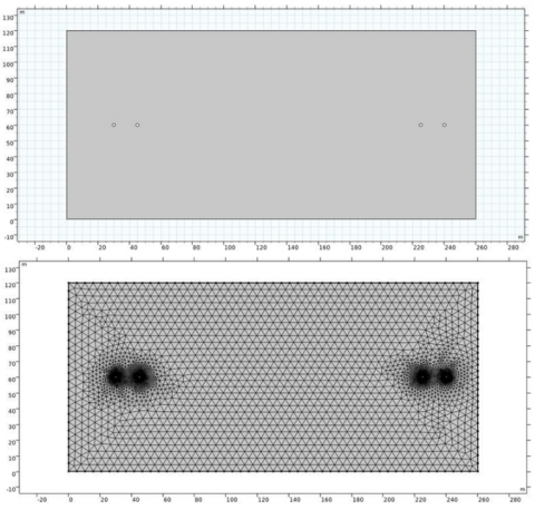
The analysis of the groundwater storage is conducted by using a thermo-fluid dynamic model, whose geometry includes, for configuration 1, the two wells connected with the district heating heat exchanger and the two wells which are connected with the heat pump. In the case of configuration 2, the same geometry is used, but the boundary conditions are imposed only on the operating wells. Figure 4 shows the system geometry and a detail of the computational mesh. In this basic configuration, the distance between the injection well associated with the district heating heat exchanger and the extraction well associated with the heat pump is 180 m, while the distance between the wells in each couple is 20 m.
The model solves fluid flow in the groundwater domain by means of the momentum and energy equations. The momentum equation is written in the form of the Darcy equation:
$\boldsymbol{v}=-\frac{k}{\mu} \nabla p$ (1)
where, v is the velocity vector, k is the ground permeability, μ is the dynamic viscosity, and p is the pressure. The continuity equation, based on the assumption of incompressible fluid, is written as:
$\nabla \cdot \boldsymbol{v}=0$ (2)
Eqs. (1) and (2) can be then rewritten in the form:
$\frac{k}{\mu} \nabla^2 p=0$ (3)
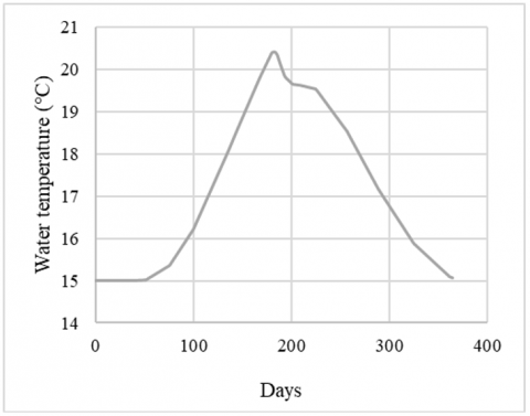
Considering the groundwater flow from left to right in Figure 4, the boundary conditions are: known velocity on the left surface (1 m/day), impermeable walls on the upper and lower surfaces, known pressure on the right surface, and known velocity on all the wells, based on the injected/extracted mass flow rate. The mass flow rates imposed in summer operation on the injection/extraction wells are obtained based on the excess energy that is available for storage. The latter quantity is shown, for the considered installation, in Figure 5. The boundary condition is obtained as a quadratic approximation of the data, imposing the conservation of the total energy over the season.
The energy equation is written in transient form:
$\lambda \nabla^2 \mathrm{~T}=\rho \mathrm{cv} \cdot \nabla \mathrm{T}+\rho \mathrm{c} \frac{\partial \mathrm{T}}{\partial \mathrm{t}}$ (4)
where, λ is the equivalent conductivity (considering the contributions of both the soil and water), T is the temperature, ρ is the density, and c is the specific heat. As for the boundary conditions, the undisturbed temperature is imposed on the left surface, and the injection temperature (22℃ in summer operation and 15℃ in winter operation) is imposed on the injection wells, while a Neumann condition is imposed on all the other surfaces, including the extraction wells.
Figure 4. System geometry and computational mesh
Figure 5. Daily values of the available thermal energy for storage
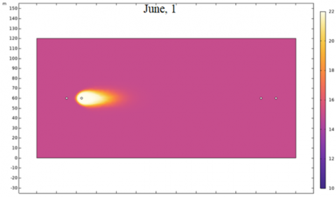
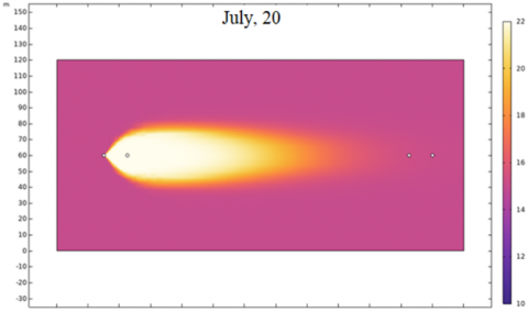
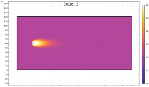
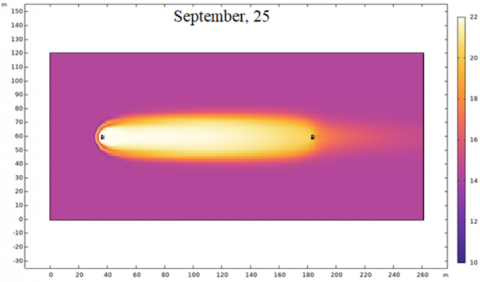
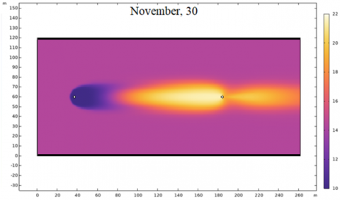
The analysis of the first configuration is performed with the goal of obtaining the time evolution of the temperature in the extraction well, which feeds the heat pump. Figure 6 shows the temperature field in a horizontal cross section of the groundwater in four different periods of the annual operation. The first three plots are associated with summer operation and these show that there is a thermal plume which starts from the injection well, grows and propagates towards the wells connected with the heat pump (which is considered not operate during summer, even if it might operate in the case it is required, for instance to locally increase the temperature of water flowing in the district heating). The last plot, instead, refers to winter conditions. In this case, it shows that the wells associated with the district heating heat exchanger do not operate, as the heat pump injects cold water into the ground, determining a cold plume which propagates downstream the installation.
Figure 6. Temperature evolution in the groundwater in the case of storage configuration 1
The annual evolution of the average temperature in the extraction well is shown in Figure 7.
Figure 7. Temperature at the extraction well for configuration 1
This piece of information, combined with the evolution of the mass flow rates, allows one to obtain the heat flux injected and extracted. These are shown in Figure 8. The annual efficiency of the storage system can be obtained as the ratio between the area below the curve of the heat extraction and that of the heat injection. In particular, the efficiency is about 50% when the distance between injection and extraction is 180 m.
The distance between the two wells is then varied in order to determine the design able to maximize the efficiency. Results are shown in Figure 9, which shows that the optimal distance between the wells is 210 m, which corresponds to an efficiency of about 52%.
Figure 8. Heat fluxes exchanged with the groundwater for configuration 1
Figure 9. Storage efficiency as a function of the distance between the wells for configuration 1
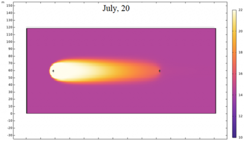
The configuration 2 previously introduced is here examined in order to evaluate the possible effects on the evolution of the temperature profiles. Figure 10 shows the temperature field in the groundwater sections in the same periods previously shown for configuration 1. With respect to Figure 6, the plume looks slightly more elongated. This is due to the larger velocity of groundwater in the area between the two wells. In the last plot, it is shown that the cold water starts flowing in the area. This represents an issue in the case of the specific installation, as the cold water is then extracted and supplied to the heat exchanger, which then reduces the amount of energy stored.
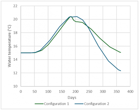
The average temperature evolution at the extraction well is shown in Figure 11 together with that for configuration 1. Results show that the second configuration presents small advantages at the peak, but then the temperature significantly drops, with a negative effect on the annual efficiency.
Figure 10. Temperature evolution in the groundwater in the case of storage configuration 2
Although the efficiency of this configuration is lower than that of configuration 1, the analysis highlights the possibility of using this configuration in different applications. In particular, in the case the heat pump is used both for heating and cooling purposes, it is possible to apply configuration 2, so that the heat released by the condenser in summer operation is discharged in the groundwater and used to feed the evaporator in winter operation in order to achieve a larger efficiency. Similarly, the cold water released by the evaporator in winter operation is injected into the groundwater to feed the condenser in summer operation.
Figure 11. Temperature at the extraction well for the two configurations
In this work, the integration of a groundwater heat pump connected with a district heating system and a groundwater storage system is analyzed. The specific issue that is considered is related to the fact that groundwater flows through the ground. To use this system as a storage, it is necessary to physically separate the charging and discharging points, so that their distance allows one to compensate for the advective transport of the thermal energy stored in the ground. The charging system is constituted by a heat exchanger which is connected, on the hot side, with the return network of the district heating. The discharging system is constituted by the groundwater heat pump.
Two configurations are examined by means of a thermo-fluid dynamic model. The first configuration is composed of four wells: two for charging the storage and two for discharging it. The optimal distance between wells is calculated, and an annual efficiency of about 52% is predicted. The second configuration consists of just two wells, which are alternatively connected with the heat exchanger and the heat pump in summer operation and winter operation, respectively. This configuration results in less efficiency than the previous one, but it is promising for different applications, such as the use of the heat pump in a reversible way, i.e., heating and cooling.
This research is part of a project funded under the National Recovery and Resilience Plan (NRRP), Mission 4 Component 2 Investment 1.3 - Call for tender No. 341 of 15.03.2022 of Ministero dell’Università e della Ricerca (MUR); funded by the European Union – NextGenerationEU.
Award Number: Project code PE0000021, Concession Decree No. 1561 of 11.10.2022 adopted by Ministero dell’Università e della Ricerca (MUR), CUP E13C22001890001, Project title “Network 4 Energy Sustainable Transition – NEST”.
|
c |
specific heat, kJ/kg·K |
|
k |
ground permeability, m2 |
|
p |
pressure, Pa |
|
T |
temperature, ℃ |
|
v |
velocity, m/s |
|
Greek symbols |
|
|
Λ |
thermal conductivity, W·m⁻¹·K⁻¹ |
|
ρ |
density, kg/m3 |
|
µ |
dynamic viscosity, kg·m-1·s-1 |
[1] DHC Market Outlook 2024. https://www.euroheat.org/data-insights/outlooks/dhc-market-outlook-2024.
[2] Directive (EU) 2023/1791 of the European Parliament and of the Council of 13 September 2023 on energy efficiency and amending Regulation (EU) 2023/955 (recast) (Text with EEA relevance). https://eur-lex.europa.eu/eli/dir/2023/1791/oj.
[3] Billerbeck, A., Breitschopf, B., Preuß, S., Winkler, J., Ragwitz, M., Keles, D. (2024). Perception of district heating in Europe: A deep dive into influencing factors and the role of regulation. Energy Policy, 184: 113860. https://doi.org/10.1016/j.enpol.2023.113860
[4] Lund, H., Werner, S., Wiltshire, R., Svendsen, S., Thorsen, J.E., Hvelplund, F., Mathiesen, B.V. (2014). 4th Generation District Heating (4GDH): Integrating smart thermal grids into future sustainable energy systems. Energy, 68: 1-11. https://doi.org/10.1016/j.energy.2014.02.089
[5] Testasecca T., Catrini P., La Villetta M., Beccali M., Piacentino A. (2025). Energy assessment of thermal solar-powered district heating and cooling networks for a cluster of buildings in Mediterranean climate. Renewable Energy, 251: 123397. https://doi.org/10.1016/j.renene.2025.123397
[6] Iordache, G.E., Ionescu, C. (2023). Integration of geothermal energy in a district heating system. In 2023 11th International Conference on Energy and Environment (CIEM), Bucharest, Romania, pp. 1-5. https://doi.org/10.1109/CIEM58573.2023.10349742
[7] Soleimani, A., Davidsson, P., Malekian, R., Spalazzese, R. (2025). Modeling hybrid energy systems integrating heat pumps and district heating: A systematic review. Energy and Buildings, 329: 115253. https://doi.org/10.1016/j.enbuild.2024.115253
[8] Romanov, D., Chakraborty, I., Holler, S. (2025). Comparative analysis of scenarios of data center waste heat utilization for district heating networks of different generations. Energy Conversion and Management, 334: 119856. https://doi.org/10.1016/j.enconman.2025.119856
[9] Zeh, R., Ohlsen, B., Philipp, D., Bertermann, D., Kotz, T., Jocic, N., Stockinger, V. (2021). Large-scale geothermal collector systems for 5th generation district heating and cooling networks. Sustainability 13: 6035. https://doi.org/10.3390/su13116035
[10] Egging-Bratseth, R., Kauko, H., Knudsen, B.R., Bakke, S.A., Ettayebi, A., Haufe, I. R. (2021). Seasonal storage and demand side management in district heating systems with demand uncertainty. Applied Energy, 285: 116392. https://doi.org/10.1016/j.apenergy.2020.116392
[11] Lanahan, M., Tabares-Velasco, P.C. (2017). Seasonal thermal-energy storage: A critical review on BTES systems, modeling, and system design for higher system efficiency. Energies 10(6): 743. https://doi.org/10.3390/en10060743
[12] Li, W., Chen, W., Huang, L., Chen, Z. (2025). Thermal performance of a seasonal aquifer energy storage system considering operational and structural characteristics. Applied Thermal Engineering, 281: 128554. https://doi.org/10.1016/j.applthermaleng.2025.128554
[13] Sorknæs, P. (2018), Simulation method for a pit seasonal thermal energy storage system with a heat pump in a district heating system. Energy, 152: 533-538. https://doi.org/10.1016/j.energy.2018.03.152
[14] Narula, K., De Oliveira Filho, F., Chambers, J., Patel, M.K. (2020). Simulation and comparative assessment of heating systems with tank thermal energy storage – A Swiss case study. Journal of Energy Storage, 32: 101810. https://doi.org/10.1016/j.est.2020.101810
[15] Lyden, A., Brown, C.S., Kolo, I., Falcone, G., Friedrich, D. (2022). Seasonal thermal energy storage in smart energy systems: District-level applications and modelling approaches. Renewable and Sustainable Energy Reviewes, 167: 112760. https://doi.org/10.1016/j.rser.2022.112760
[16] Gizzi, M., Vagnon, F., Taddia, G., Lo Russo, S. (2023). A review of groundwater heat pump systems in the Italian framework: Technological potential and environmental limits. Energies, 16(12): 4813. https://doi.org/10.3390/en16124813
[17] Schiubuola, L., Tambani, C. (2022). Environmental impact and energy performance of groundwater heat pumps in urban retrofit. Energy & Buildings, 261: 111964. https://doi.org/10.1016/j.enbuild.2022.111964
[18] Capone, M., Canino, M., Guelpa, E. (2026) Dynamic temperature supply to boost the integration of renewable energy into existing district heating networks. Renew Energy, 256: 124315. https://doi.org/10.1016/J.RENENE.2025.124315
[19] Bloemendal, M., Olsthoorn, T. (2018). ATES systems in aquifers with high ambient groundwater flow velocity. Geothermics 75: 81-92. https://doi.org/10.1016/j.geothermics.2018.04.005
[20] Capone, M., Verda, V. (2024). Integration of groundwater storage and heat pumps in second-generation district heating systems. Journal of Sustainability for Energy, 3(4): 278-286. https://doi.org/10.56578/jse030406