Ali H. Numan*![]() | Ashwaq Q. Hameed
| Ashwaq Q. Hameed![]()
© 2025 The authors. This article is published by IIETA and is licensed under the CC BY 4.0 license (http://creativecommons.org/licenses/by/4.0/).
OPEN ACCESS
This paper presents performance optimization of model predictive torque control (MPTC) fed permanent magnet synchronous machine (PMSM) drives based on photo-voltaic (PV) systems. The inaccurate selection of proportional-integral (PI) speed controller parameters used in MPTC can deteriorate the dynamic response of the drive. These parameters have been optimized using PI and a rigid nature-inspired salp swarm algorithm (PI-SSA), and accordingly, the system stability has improved. The precise selection of the boost dc-dc converter's duty period contributes to maximizing the extracted power and increases the efficiency of the PV arrays during variations in solar radiation. The particle swarm optimization-based maximum power point tracking (PSO-MPPT) has been applied to optimize the performance of the DC power converter fed by a two-diode PV array model. The PI controller and PI-based gray wolf optimization (PI-GWO) controller performances have been evaluated by comparison with the suggested approach. The MATLAB simulation results revealed that the suggested method provides robustness to variations in speed and torque commands, improving the settling time, rise time, and overshoot dynamic response of the system, while also increasing system efficiency by mitigating motor current total harmonic distortion (THD).
PMSM, PV, MPTC, PI, PI-GWO, PI-SSA, PSO-MPPT, THD, SVPWM
The issues of climate changes, the absence of electricity in rural areas, and rising fossil fuel prices have encouraged consumers to use alternative energy sources for electricity generation. Solar photovoltaic (PV) is considered one of the fastest-growing renewable energy sources due to its increased efficiency, scalability, modularity, and silent operation [1]. Water purifying and pumping systems are vital and cost-effective applications for PV systems, especially in off-grid conditions and remote regions. Furthermore, diesel pump fuel costs and regular maintenance are two to four times higher than those of PV water pump systems [2]. These pumps depend highly on the control strategies of the electric motors to adjust the discharge rate. PMSMs have been widely used in PV water pumping systems for their inherent high efficiency, higher power density, excellent torque density, best power factor, and compact size [3, 4].
There are two most popular high-dynamic performance control methods of PMSMs, which are called vector controlled (VC) [5] and direct torque control (DTC) [6]. The problem with the Field Oriented Control (FOC) is the difficulty of tuning gains contained in the cascaded control loops. The dynamic torque response of the FOC is slower than that of the DTC [7]. However, the DTC suffers from using bang-bang hysteresis controller of flux and torque loops, leading to increased electromagnetic torque and flux ripples that generate audible noise and vibrations, deteriorating the motor performance accordingly [8]. These defects have been avoided by combining DTC with space vector modulation (DTC-SVM), but with increased system complexity [9]. On the other hand, model predictives torque control (MPTC) has been proposed as an ideal alternative modern control technique to classical FOC and DTC because of its simplicity in structure and implementation [10]. Moreover, the inner proportional-integral (PI) regulator of the torque and current loop has been removed in the MPTC to improves the transients response of the control systems.
The cascaded structure of predictive control for induction motors has been utilized to improve the transient behavior of the outer speed loop [11]. However, the realization of this method is complicated since the sampling times used for the outer speed loop are tenfold larger than in the inner torque and current loop, which leads to a high calculation time. In the study by Belda and Vošmik [12], the speed and position of the PMSM have been controlled using generalized predictive control (GPC). The control method introduced an excellent transient response, but with a computational burden. Three prediction horizons for the direct speed control based on the predictive model technique have been implemented to overcome some limitations in electrical and mechanical time constants [13]. However, this method takes a long time to complete calculations, which can be a drawback. Therefore, one prediction horizon has been presented to minimize the calculation burden for the predicted speed control strategy and increase the weight factor used in the design of the cost functions [14]. These weighting factor need tuning by trial/error, which is a hard-working method. A comparative study of speed control loop optimization algorithms for vector-controlled PMSM reveals that the system dynamic performances can be improved through metaheuristic optimization tools [15]. However, a simplified model of PMSM based on a transfer function has been used instead of a detailed PMSM model, which would reduce the accuracy of the dynamic response.
In this work, an approach to improves and optimizes the dynamic performance of the MPTC for PMSM drives fed PV water pumping system using a proportional-integral-based salp swarm algorithm (PI-SSA). The robust SSA has been applied to fine-tune and parameter optimization of the PI speed loop. Furthermore, the efficiency of the PV array with two diode models has been enhanced using particle swarm optimization combined with maximum power point tracking (PSO-MPPT).
The rests of this article is arranged as following. Section Two introduces a complete description of the proposed control structure and mathematical models of their elements. The MATLAB simulation results of the proposed PI-SSA controller and the performance evaluation with the traditional PI and PI optimized by grey wolf optimizer (PI-GWO) controllers are presented in Section Three. In Section Four, the concluded remarks are drawn.
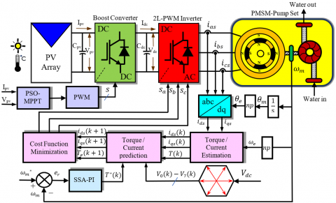
The complete description for the proposed robust speed controller for MPTC of PMSM drive-based PV water pumping system is shown in Figure 1.
Figure 1. Block diagram of the proposed optimized MPTC of PMSM drives
This system comprises (from left to right) a PV array, an input capacitor Cpv, a boost dc-dc converters controlled by PSO-MPPT, a three-phase 2-level pulse width modulation (2L-PWM) inverter, an output capacitor Cdc, also called a dc-link capacitor, and PMSM mechanically connected with a centrifugal water pump. The electrical power is generated when the PV array is exposed to sufficient solar radiation. The dc-link of the VSI utilizes the electrical power generated and converts it into controlled electrical power to supply the PMSM with suitable power.
The flow of water in the water pumping system is controlled by adjusting the speed of the PMSM. The input and output capacitors are used to mitigate ripples in the current drawn by the converters and overcome the inherent nonlinearity effects of PV modules. However, the output capacitor selection is more critical than the input capacitor because the boost converter utilizes an inductor in series at the input, contributing to reducing ripples.
The power of the single PV module is usually smaller than the required power for supplying the PMSM with sufficient power. Therefore, a series / parallel combination of PV modules is arranged to form a PV array capable of supplying the PMSM with the appropriate power.
2.1 Modeling and design of PV array
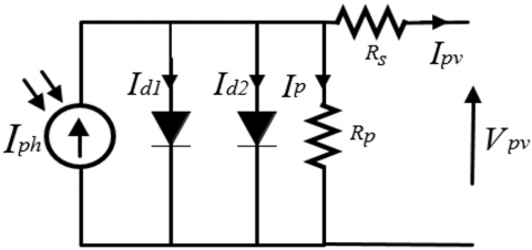
The two-diode model has been used in modeling the PV module to enhances the accuracy and reliabilities of the simulation results by considering the recombination loss in this model as compared with the single-diode model [16]. Figure 2 shows a schematic representation of the two-diode PV module. The utilized PV array has three series-connected 250 W PV modules to increase the output voltage fed to the boost dc-dc converter and two 250W PV modules parallel connected to amplify the output current. However, the total PV array power capacity of 1250 kW exceeds the PMSM power to accommodate the motors and the two converters' electrical and mechanical losses. Therefore, the output currents of the PV arrays can be given as [16, 17]:
$I_{p v}=I_{p h}-I_{d 1}-I_{d 2}-I_p$ (1)
$\begin{aligned} & I_{p v}=I_{p h} N_{p m} \\ & -N_{p m}\left\{I_{s a t 1}\left[\exp \left(\frac{q\left(V_{p v}+I_{p v} R_s\left(\frac{N_{s m}}{N_{p m}}\right)\right)}{N_{s c} A_1 k T}\right)-1\right]\right. \\ & \left.-I_{s a t 2}\left[\exp \left(\frac{q\left(V_{p v}+I_{p v} R_s\left(\frac{N_{s m}}{N_{p m}}\right)\right.}{N_{s c} A_2 k T}\right)-1\right]\right\} \\ & -\left(\frac{V_{p v}+I_{p v} R_s\left(\frac{N_{s m}}{N_{p m}}\right)}{R_p\left(\frac{N_{s m}}{N_{p m}}\right)}\right)\end{aligned}$ (2)
where, Iph, Isat1, Isat2, and Ipv, are photocurrent, diode-reverse saturation current by diode one and diode two that represent recombination loss in the depletion region, and the array output current, respectively; Vpv, q, k, and T, are the array output voltage, electron charges ($1.6 \times 10^{-19} \mathrm{C}$), Boltzmann's ($1.38 \times 10^{-23} \mathrm{~J} / \mathrm{K}$), and cell temperature, respectively; A1, A2, Nsc, Nsm, and Npm are the diode one and diode two ideality factors, and the number for series cells connected in a module, the number of series and parallel modules connecting in an array, respectively; Rp, and Rs are the parallel / series module resistances, respectively. The specifications of the PV module model are SPR-X2-250-BLK manufactured by SunPower, and the designed PV array is given in Table 1.
Figure 2. Equivalent two-diode circuit of PV module
Table 1. Parameters for PV module and array
|
PV Module |
PV Array |
||
|
Parameters |
Values |
Parameters |
Values |
|
Max power (1000 W/m2, 25℃), $P_{\max }$ |
250 W |
Max power array power, $P_{ {maxarr }}$ |
1250 W |
|
Voltage at open circuit, $V_{o c}$ |
50.93 V |
Open circuit array voltage, $V_{{ocarr }}$ |
152.7 V |
|
Current at short circuit, $I_{sc}$ |
6.2 A |
Short circuit array current, $I_{{scarr }}$ |
12.4 A |
|
Voltage at max. power, $V_{m p}$ |
42.8 V |
Max power array voltage, $V_{{mparr }}$ |
128.4 V |
|
Current max. power, $I_{m p}$ |
5.84 A |
Max power array current, $I_{{mparr }}$ |
11.68 A |
|
The temperature constant of $V_{o c}, K_v$ |
-0.291 V/℃ |
No. PV modules required, $N$ |
5 |
|
The temperature constant of $I_{s c}, K_i$ |
0.013306 A/℃ |
No. series-connected module, $N_{s m}$ |
3 |
|
No. of series-connected cells, $N_{s c}$ |
72 |
No. parallel- connected modules, $N_{p m}$ |
2 |
2.2 Modeling and design of a boost dc-dc converter
The boost dc-dc converters provide a voltage at the output greater than the input for supplying a PV solar water pump with sufficient voltage and max. power extraction from the PV array under variable radiation conditions. The duty cycle of this converter’s at steady state conditions can be expressed by Eq. (3) [18].
$D=\frac{V_{d c}-V_{p v}}{V_{d c}}$ (3)
where, $V_{d c}$ is the inverter side voltage, $V_{pv}$ is the voltage at the PV side, and $D$ is the duty cycle of the boost converter. The estimated values of the inductor and the capacitor of the boost converter under continuous conduction mode (CCM) operation can be given by the following equations [19]:
$L_{\text {boost }}=\frac{V_{p v}\left(V_{c k}-V_{p v}\right)}{V_{d c} \Delta I_L f_{s w}}$ (4)
$C_{\text {boost }}=\frac{I_{d c}\left(V_{d c}-V_{p V}\right)}{V_{d c} \Delta V_o f_{s w}}$ (5)
The $f_{s w}$ is switching frequency (12 kHz), $\Delta I_L$ is the estimated maximum amplitude of the current ripple at the inductor terminals of (20%), $\Delta V_o$ is the peak voltage ripple at the output capacitor of (1%). The design parameters of the boost dc-dc converter are reported in Table 2.
Table 2. Parameters of boost dc-dc converter
|
Parameters |
Values |
|
Boost inductor, $L_{\text {boost }}$ |
2 mH |
|
Boost capacitor, $C_{\text {boost }}$ |
150 µF |
|
Switching frequency (IGBT), $f_{s w}$ |
12 kHz |
|
Capacitor at the PV side, $C_{p v}$ |
16 µF |
|
dc-link capacitor at the inverter side, $C_{d c}$ |
63 µF |
The input capacitor ensures that the dc-dc boost converter will operate efficiently at the max. power point and reduce ripple in the PV arrays voltage output. This capacitor can be calculated as [20]:
$C_{p v}=\frac{D}{8 L_{\text {boost }} \Delta V_{p v} f_{s w}^2}$ (6)
where, $\Delta V_{p v}$ is the ripple of the output voltage from the PV array measured at the PV capacitor side (1% typical value).
2.3 PSO-MPPT controlled boost dc-dc converter
The PSO-MPPT efficiently enhances the operation of the boost dc-dc converter by maximizing the extraction of power capability from the PV modules at variable solar radiation. The PSO is an intelligent, metaheuristic evolutionary search algorithm that efficiently computes local and global MPPT. The particles, also called a swarm of the PSO algorithm, represent candidate solutions. Therefore, the best position Pbest of these particles is affected by neighborhood particles, and all the particles find the best solution Gbest in the entire population. The position of particles has been computed as follows [21]:
$x_i^{t+1}=x_i^t+\phi_i^{t+1}$ (7)
Also, the velocity of particles has been computed as:
$\phi_i^{t+1}=w \phi_i^t+c_1 r_1\left(P_{\text {best } i}-x_i^t\right)+c_2 r_2\left(G_{\text {best }}-x_i^t\right)$ (8)
$i=1,2 \ldots, n_p$
where, $w$, $c_1$, $c_2$, $r_1$, $r_2$, $t$, and $n_p$ are weight constant inertia, accelerations coefficient, distributed random numbers uniformly between zeros and ones, the iteration current positions, and the number of particles, respectively. The initial PSO algorithm parameters have been depicted in Table 3.
Table 3. Parameters of PSO
|
Parameters |
Values |
|
Inertia weight constant, w |
0.9 |
|
Acceleration coefficient, c1 |
0.8 |
|
Acceleration coefficient, c2 |
1.9 |
|
Random numbers, r1, r2 |
[0,1] |
|
No. of particles, np |
25 |
The actual duty period of the boost dc-dc converter will be represented as the particle's position, while the velocity has been considered as the perturbations of the current duty period. Then, Eq. (7) can be written as follows [21]:
$D_i^{t+1}=D_i^t+\phi_i^{t+1}$ (9)
The objective functions of the PSO are defined as:
$P\left(D_i^t\right)>P\left(D_i^{t-1}\right)$ (10)
The PSO will start optimization steps by computing three different duty periods, $D_i(i=1,2,3)$ that represented three particles, then transmitted into the dc-dc boost converter.
2.4 Modeling and design of the dc-link side
The value of the capacitor at the dc-link side is estimated from energy conservation relations as [21]:
$C_{d c}=\frac{2 S \gamma_{V S I} t}{\left(V_{d c, \min }^2-V_{d c, \max }^2\right)}$ (11)
where, $S, \gamma_{V S I}, t, V_{d c, \min }$, and $V_{d c, \max }$ are the inverter kVA rating, the safety factor for overloading the inverter, the time duration to restore the minimum dc-link voltage, and the minimum, as well as maximum values of the dc-link voltage, respectively.
The accurate selection of dc bus voltage is crucial to maintain the VSI operating within the proper limits, and this voltage should be greater than the double peak phase voltage of the motor. The relationships between dc-bus voltage and ac line-to-line voltage in a PWM inverter can be expressed as [22]:
$V_{d c}=\frac{2 \sqrt{2} V_{a c, L L}}{M \sqrt{3}}$ (12)
where, $V_{a c, L L}$ and $M$ are the ac line-to-line voltage and modulation index under normal or overmodulation operation conditions, respectively.
2.5 Dynamic modeling of PMSM
The derivation of the mathematical model for the motor can be simplified by assuming that the saturation is canceled, the back electromotive forces (emfs) is sinusoidal, and eddy current and hysteresis losses are negligible. According to these assumptions, the continuous-time dynamic model can be obtained using synchronous rotating reference frame transformation of the electrical and mechanical subsystems. The electrical subsystem in the d-q axis voltage equation can be described as [23, 24]:
$v_{d s}=R_s i_{d s}+L_{d s} \frac{d i_{d s}}{d t}-\omega_e L_{q s} i_{q s}$ (13)
$v_{q s}=R_s i_{q s}+L_{q s} \frac{d i_{q s}}{d t}+\omega_e\left(L_{d s} i_{d s}+\lambda_{P M}\right)$ (14)
where, $v_{d s}, v_{q s}$ denotes the d-q axis of the stator voltages in the synchronously rotating frame, $i_{d s}, i_{q s}$ represent the d-q axis of the stator currents in the synchronously rotating reference frame, $R_s$ is the stator resistance, $L_{d s}, L_{q s}$ are the d-q axis stator winding inductances, $\lambda_{P M}$ is the flux linkage produced by permanent magnets in the rotor, and $\omega_e$ is the rotor's electrical angular speed, respectively. The instantaneous electromagnetic torque can be given as [24]:
$T_e=3 P i_{q s}\left[\lambda_{P M}+\left(L_{d s}-L_{q s}\right) i_{d s}\right] / 2$ (15)
The d-q axis inductances of the surface-mounted PMSM are equal to each other because of a uniform air gap (i.e., $L_{d s}=L_{q s}=L_s$). Thus, the equation of torque can be simplified to:
$T_e=3 P i_{q s} \lambda_{P M} / 2=k_t i_{q s}$ (16)
where, $k_t$ is the motor torque constant. The flux linkage of the stator can be defined as:
$\psi_{d s}=L_{d s} i_{d s}+\psi_{P M}$ (17)
$\psi_{q s}=L_{q s} i_{q s}$ (18)
$\psi_s=\sqrt{\left(\psi_{ds}\right)^2+\left(\psi_{q s}\right)^2}$ (19)
The mechanical speed subsystem can be expressed as [23]:
$\omega_m=\int \frac{1}{J}\left(T_e-T_l-B \omega_m\right) d t$ (20)
where, $P$ is the pole pairs, $T_l$ is the load torque, $\omega_m$ is the mechanical rotational speed of rotor, $J$ is the shaft inertia, and $B$ is the damping constant, respectively. The rotor electrical angular speed is related to the rotor mechanical angular speed by $\omega_e=P \omega_m$ [25]. The MPTC is based on predicting the next value of motor torque and stator currents in the next sampling time using a discrete-times model. Therefore, the Euler-forward discretization method can be used to develop a mathematical model in discrete time of the Eqs. (13) and (14), and Eq. (16) at the time $(k+1)$ as follows [26, 27]:
$\begin{aligned}
& \frac{i_{d s}(k+1)-i_{d c}(k)}{T_s}=\left(-\frac{R_s}{L_{d s}}\right) i_{d s}(k)+\left(\frac{L_{q s}}{L_{d s}}\right) \omega_e i_{q s}(k)+\left(\frac{1}{L_{d s}}\right) v_{d s}(k)
\end{aligned}$ (21)
$\begin{aligned} & \frac{i_{q s}(k+1)-i_{q s}(k)}{T_s} \\ & =\left(-\frac{R_s}{L_{q s}}\right) i_{q s}(k)-\left(\frac{L_{d s}}{L_{q s}}\right) \omega_e i_{d s}(k) \\ & -\left(\frac{1}{L_{q s}}\right) \omega_e \lambda_m+\left(\frac{1}{L_{q s}}\right) v_{q s}(k)\end{aligned}$ (22)
where, $T_s$ is the sampling interval.
The torque and flux of the PMSM are considered as the control objectives of the cost functions, which is expressed as follows:
$F_c=\left|T_e^*-T_e(k+1)\right|+\lambda_f \cdot\left\|\psi_s^*|-| \psi_s(k+1)\right\|$ (24)
where, $\lambda_f$ is the weighting factor of the torque and flux control objectives.
2.6 Modeling and design of the centrifugal pump
The centrifugal pump is optimum for continuous duty applications rather than the volumetric pump because it can extract the max. available power of the PV array even at low solar radiation levels, and the load line is near the max. power point (MPP) line [28]. The load model is usually expressed as load torque applied to the motor shaft. However, the relationship between motor speed and load torque in water pumps is nonlinear. Therefore, the load torque is proportional directly to the square of the rotor mechanical angular speed as follows [29]:
$T_l=K_{w p} \omega_m^2$ (25)
where, $K_{w p}$ is the constant of the water pump that is calculated as [30]:
$K_{w p}=\frac{P_m}{\omega_m^3}$ (26)
2.7 The 2L-PWM inverter mathematical model
The 2L-PWM inverter is one of the most commonly used converters for motor drives due to its availability in markets, simple structure, and high dynamic performance. This converter can produce six active and two non-active voltage vectors. The inverter voltage output vectors in the stationary reference frame are computed from the dc-link voltage (Vdc) and the switchings signals ($S_a$, $S_b$, and $S_c$) as follows [12]:
$v_\alpha=\frac{V_{d k}}{3} *\left(2 S_a-S_b-S_c\right)$ (27)
$v_\beta=\sqrt{3}\left(-S_c\right)$ (28)
This section will use the proposed robust nature-inspired intelligent PI-SSA to optimize the PI speed controller. The PI-SSA controller and the objective function are modeled and simulated in MATLAB software and then applied to MPTC-fed three-phase surface-mounted PMSM drives. The results are compared with a classical PI speed controller and PI-GWO. A brief description of the proposed PI-SSA optimization algorithms is presented in the following subsections.
3.1 PI-SSA speed controller
The salp swarm algorithm (SSA) was invented by Mirjalili et al. to solve extensive computational real-world optimization problems in the presence of unknown spaces accurately at the fastest convergence speed [31]. The behavior of the salps in the water is similar to that of the leader responsible for guiding the followers of the swarm group. The updated position of the leader can be written as:
$P_n^1(t+1)= \begin{cases}P_{T n}(t)+c_1\left(c_2\left(u b_n-l b_n\right)+l b_n\right) & c_3 \geq 0.4 \\ P_{T n}(t)-c_1\left(c_2\left(u b_n-l b_n\right)+l b_n\right) & c_3<0.4\end{cases}$ (29)
where, $P_n^1$ represent the position of the leader in the nth dimension, $P_{T n}$ is the position of the target in the nth dimension, $u b_n$ is the upper bound of the nth dimension, $l b_n$ stands for the lower bound of the nth dimension, $c_2$ and $c_3$ are uniformly random numbers of [0,1]. The exploration and exploitation are balanced in the SSA using the coefficient $c_1$, which is formulated as follows:
$c_1=2 e^{-\left(\frac{4 m}{M}\right)^2}$ (30)
where, $m$ is the present iteration, $M$ is the maximum allowed number of iterations.
The follower's position is updated using Newton's law of motion and can be written as:
$P_n^i(t+1)=0.5\left(P_n^{i-1}+P_n^i\right)$ (31)
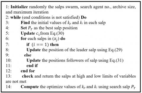
The pseudo-code for the SSA algorithm is shown in Figure 3.
Figure 3. Pseudo-code for the SSA algorithm
The MPTC suffers from unsatisfactory dynamic performance of the PI speed controller loop due to conventional tuning methods of the controller parameters, such as trial and error, Ziegler-Nichols (ZN), Cohen-Coon (CC) approaches. However, these tuning techniques cannot present the rigorous level of control required presently. Therefore, the SSA algorithm will minimize the targeted function and produce the best values of the PI speed controller parameters. The PI speed controller overshoots, oscillations, and settling time can be highly minimized by considering the performance index integral of the time-weighted absolute error (ITAE) as an objective function. The performance index formula of ITAE is as follows:
$\operatorname{ITAE}=\int_0^{t_s}|e(t)| t d t$ (32)
where, $e(t)$ is the difference between the controlled variable and the set point, and $t_S$ is the time. The PI speed controller can be mathematically expressed as:
$T^*(k)=e_r k_p+k_i \int_0^{t_s} e_r d t$ (33)
where, $e_r$ is the motor speed error $k_i$ and $k_p$ are the integral and proportional gains, respectively.
This section addresses MATLAB simulation-based results and analysis of the proposed improved MPTC of PMSM drives for PV water pumping systems. The proposed PI-SSA controller's effectiveness is validated by comparison with two controllers under variable motor speed and PV operating conditions. The main parameters of the PMSM and water pump are listed in Table 4.
Table 4. Design parameters of SPMSM and water pump set
|
Parameters |
Values |
|
Rated power, $P_r$ |
1100 W |
|
Rated torque, $T_r$ |
3.5 Nm |
|
Number of poles, $P$ |
2 |
|
Rated speed, $\omega_m$ |
3000 rpm(314.16 rad/s) |
|
Stator resistance, $R_s$ |
2.41 Ω |
|
Stator winding inductances, $L_s$ |
8.5 mH |
|
Rotor flux linkage, $\lambda_m$ |
0.2456 V/(rad-s) |
|
Moment of inertia, J |
0.003041 kg.m2 |
|
Damping constant, $B$ |
0.00073 kg.m/s2 |
|
Water pump constant, $K_w$ |
2.7*10-4 Nm/(rad-s)2 |
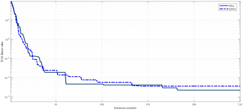
The convergence curve has been used to evaluate the effectiveness of the proposed algorithms and compare them against other metaheuristic methods. Figure 4 compares the convergence curves of the proposed SSA and GWO using ITAE as an objective function for 250 iterations. The results clearly shows that the proposed SSA required 182 iterations to attain the fitness value of 22.5×10⁻⁴ compared to GWO.
Figure 4. Convergence curve of SSA and GWO metaheuristic optimization techniques
The GWO algorithm parameters used in the simulation are listed in Table 5.
Table 5. Parameters of GWO algorithm
|
Parameters |
Values |
|
Population size, N |
18 |
|
Maximum iterations, Maxiter |
350 |
|
Number of variables, a |
2 |
|
Upper bound, ub |
1 |
|
Lower bound, lb |
0 |
The tuning procedures of the PI speed controller were conducted using traditional ZN, GWO, and the proposed SSA algorithm. The Kp and Ki gains after the tuning process are depicted in Table 6.
Table 7 presents a comparison of PI, PI-GWO, and proposed PI-SSA controllers dynamic performance in terms of rise time, settling time, overshoot, and undershoot based on ITAE as an error minimization method. It can be seen from Table 6 that the proposed PI-SSA introduced the best dynamic response with the fastest rise time, best settling time, and the least percentage of overshoot and undershoot at three different motor speeds compared to PI and PI-GWO controllers.
Table 6. ZN, GWO, and SSA PI speed controller parameters
|
Parameters |
ZN |
GWO |
SSA |
|
KP |
2.0351 |
1.8258 |
1.9475 |
|
KI |
0.8643 |
0.7984 |
0.7157 |
Table 7. Performance indices of PI, PI-GWO, and proposed PI-SSA controllers under different motor speeds
|
Speed |
Control Technique |
Rise Time (ms) |
Settling Time (ms) |
Overshoot (%) |
Undershoot (%) |
|
500 rpm |
PI |
0.973 |
7.746 |
38.281 |
16.889 |
|
PI-GWO |
0.796 |
2.491 |
9.840 |
7.369 |
|
|
PI-SSA |
0.767 |
1.542 |
5.763 |
4.972 |
|
|
1000 rpm |
PI |
1.661 |
11.944 |
22.492 |
10.339 |
|
PI-GWO |
1.339 |
3.417 |
3.943 |
4.347 |
|
|
PI-SSA |
1.281 |
2.878 |
2.758 |
2.216 |
|
|
2000 rpm |
PI |
1.557 |
10.548 |
18.452 |
7.885 |
|
PI-GWO |
1.262 |
2.546 |
3.351 |
3.205 |
|
|
PI-SSA |
1.168 |
1.988 |
1.831 |
2.198 |
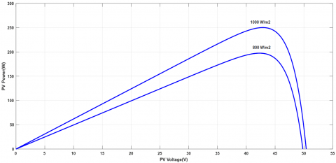
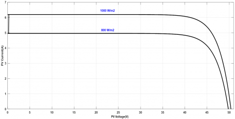
The power versus voltage of the PV module with the corresponding current and voltage characteristics at 1000 w/m2 and 800w/m2 solar irradiation are illustrated in Figures 5 and 6, respectively. The power versus voltage and short circuit current versus voltage of the PV module are identical to the data given in Table 1. This process will confirm that the generated power by the PV module is similar to that of a real module.
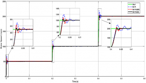
Figure 7 shows the motor speed response to a step-change in reference speed when the motor speed instantly increases from 0-500 rpm at a time range of 0-0.2 s, followed by an increase in speed from 500-1000 rpm at a time range of 0.2 s-0.4 s, and finally by the rise in the speed from1000-2000 rpm at a time range of 0.4 s-0.6 s with a rated load torque of 3.5 Nm. The step change in the motor speed is considered the pumping system's actual performance when the water flow rate is not constant. The steady and dynamic state responses of the proposed PI-SSA controller are verified by comparing their results with those of the PI and PI-GWO controllers. The proposed PI-SSA controller improves the rise time by 21.17%, 3.64% at 500 rpm, 22.81%, 4.33% at 1000 rpm, and 24.93%, 7.44% at 2000 rpm over PI and GWO-PI controllers. Furthermore, the settling time increased by 80.1%, 38.1% at 500 rpm, 75.91%, 15.77% at 1000 rpm, and 81.15%, 21.91% at 2000 rpm over PI and PI-GWO controllers. Also, the overshoots were enhanced by 84.94%, 41.43% at 500 rpm, 87.73%, 30.14% at 1000 rpm, and 90.17%, 45.35% at 2000 rpm over PI and PI-GWO controllers. Finally, the undershot improvement of 70.53%, 32.52% at 500 rpm, 78.57%, 49.02% at 1000 rpm, and 72.12%, 31.42% at 2000 rpm over PI and PI-GWO controllers. The superior transient performance of rise time, settling time, overshot, and undershot at different operation conditions is due to the inherent robustness and stability of the proposed technique.
Figure 5. Typical power-voltage curve of the PV module
Figure 6. Typical current-voltage curve of the PV module
Figure 7. Motor speed response to three-step changes in reference speed
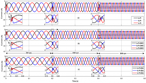
Figure 8. Three-phase motor current waveforms at a three-steps change in motor speeds and rated load torques
Furthermore, the corresponding three-phase motor current waveforms at motor speeds (500 rpm,1000 rpm, and 2000 rpm) are observed in Figure 8. It is evident that the PI, PI-GWO, and proposed PI-SSA controllers generate similar sinusoidal stator current waveforms at steady state conditions, but when using fast fourier transform (FFT) on these waveforms, the proposed PI-SSA has the lowest line current total harmonic distortion (THDi) factor and smallest line current disturbance during a sudden change in motor speed at 0.2s and 0.4s. The THDi of the motor line currents are depicted in Table 8. The average value of THDi was 15.55% using a conventional PI controller which led to producing high harmonic contents but using the PI-GWO this value was reduced to 7.7% which can be considered as a relative improvement and the best performance among all controllers comes when using the PI-SSA controller where the THDi was 19.4% improved over conventional PI controller which indicates more sinusoidal smoother motor currents.
Table 8. THDi of three-phase motor currents
|
|
Phase A |
Phase B |
Phase C |
|
THDi (PI) |
15.38% |
15.41% |
15.87% |
|
15.55% Avg. |
|||
|
THDi (PI-GWO) |
14.21% |
14.74% |
14.11% |
|
14.35% Avg. |
|||
|
THDi (PI-SSA) |
12.96% |
12.39% |
12.24% |
|
12.53% Avg. |
|||
The dynamic response of the electromagnetic torque at motor speeds (500 rpm, 1000 rpm, and 2000 rpm) and 3.5 Nm rated load torque is shown in Figure 9. It is clear from the results that when the motor speed changes from 500 rpm to 1000 rpm at 0.2 s, then increases to 2000 rpm at 0.4 s, the proposed PI-SSA controller performs better than the PI controller and the PI-GWO controller.
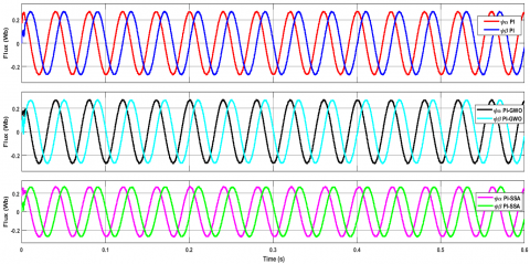
The stator flux magnitude in $\alpha-\beta$ coordinate using various controllers is depicted in Figure 10. It can be seen from the results that the proposed PI-SSA controller is smoother at motor speed step change than the PI controllers and the PI-PSO controllers.
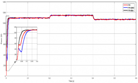
The power delivered to the PMSM from the PWM inverter is shown in Figure 11. As can be seen, the proposed controller introduces much better consumed power by the motor.
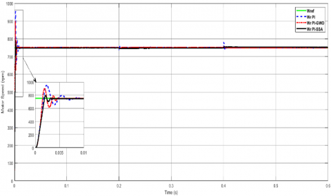
The dynamic speed response of the MPTC-PMSM drives using the proposed controller was also validated at a constant reference speed of 750 rpm and variable load torque, as shown in Figure 12. The dynamic responses of the PI-SAA controller perform much better than those of the PI and PI-GWO controllers, even when the motor load torque has been changed during this condition.
The three-phase stator currents for the PMSM in dynamic and steady states are shown in Figure 13. It is obvious from the results that the stator currents during motor start-up using the PI controller are more disturbed and fluctuate than the PI-GWO controller, and the best current behavior was when using the proposed PI-SSA controllers.
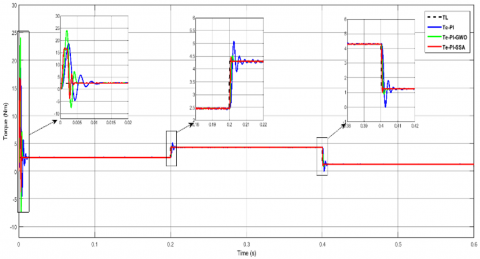
The electromagnetic torque in the variation of load torque (2 Nm, 3.5 Nm, and 1 Nm) and constant motor speed is demonstrated in Figure 14. The MATLAB simulation results reveal that the suggested PI-SSA controllers improves the dynamic performance of the developed motor torque even when the motor load torque increases from 2 Nm to 3.5 Nm at 0.2 s and steps down to 1 Nm at 0.4 s.
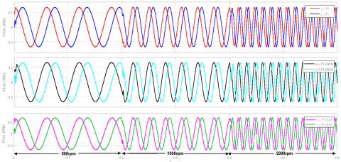
The PMSM flux linkage in ($\alpha-\beta$) coordinate at constant speed (750 rpm) and variable load torque (2 Nm,3.5 Nm, and 1 Nm) is illustrated in Figure 15. It is noted that the flux linkage dynamic response using the proposed PI-SSA controller is less distorted at the starting time compared to the other two controllers and similar in the steady state.
Figure 9. Electromagnetic torque response to rated load torque and variable motor speed
Figure 10. The $\alpha-\beta$ flux linkage waveforms of the PMSM under variable motor speed constant rated load torque
Figure 11. Electrical power supplied to PMSM
Figure 12. Comparison of motor speed responses at constant reference speed (750 rpm)
Figure 13. Three-phase motor stator current waveforms at constant motor speed and step change in load torque
Figure 14. Electromagnetic torque response to the three-step changes in load torque and variable motor speeds
Figure 15. The $\alpha-\beta$ motor flux waveforms at motor speed (750 rpm) and a step change in load torque
In this paper, the dynamic performance and the efficiency of the MPTC for PMSM-powered by PV water pumping systems have been optimized by using robust nature-inspired intelligent PI-SSA for the speed controller and PI-PSO for the boost converter of the PV system. The proposed PI-SSA speed controller was validated by conducting several simulation tests with three motor speeds (500 rpm,1000 rpm, and 2000 rpm) and comparing the results with PI and PI-GWO controllers. The MATLAB simulation results shows that the proposed PI-SSA controller improves the rise time by 21.17%, 3.64% at 500 rpm, 22.81%, 4.33% at 1000 rpm, and 24.93%, 7.44% at 2000 rpm over PI and PI-GWO controllers. Furthermore, the settling time increased by 80.1%, 38.1% at 500 rpm, 75.91%, 15.77% at 1000 rpm, and 81.15%, 21.91% at 2000 rpm over PI and PI-GWO controllers. Also, the overshoots were enhanced by 84.94%, 41.43% at 500 rpm, 87.73%, 30.14% at 1000 rpm, and 90.17%, 45.35% at 2000 rpm over PI and PI-GWO controllers. Finally, the undershot improvement of 70.53%, 32.52% at 500 rpm, 78.57%, 49.02% at 1000 rpm, and 72.12%, 31.42% at 2000 rpm over PI and PI-GWO controllers.
[1] Kashif, M., Murshid, S., Singh, B. (2020). Solar PV array fed self-sensing control of PMSM drive with robust adaptive hybrid SOGI based flux observer for water pumping. IEEE Transactions on Industrial Electronics, 68(8): 6962-6972. https://doi.org/10.1109/TIE.2020.3003656
[2] Reca, J., Torrente, C., López-Luque, R., Martínez, J. (2016). Feasibility analysis of a standalone direct pumping photovoltaic system for irrigation in Mediterranean greenhouses. Renewable Energy, 85: 1143-1154. https://doi.org/10.1016/j.renene.2015.07.056
[3] Naikawadi, K.M., Patil, S.M., Kalantri, K., Dhanvijay, M.R. (2022). Comparative analysis of features of online numerical methods used for parameter estimation of PMSM. International Journal of Power Electronics and Drive Systems (IJPEDS), 13(4): 2172-2180. https://doi.org/10.11591/ijpeds.v13.i4.pp2172-2180
[4] Bdewi, M.Y., Mohammed, A.M., Ezzaldean, M.M. (2021). Design and performance analysis of permanent magnet synchronous motor for electric vehicles application. Engineering and Technology Journal, 39(3 Part A): 394-406. https://doi.org/10.30684/etj.v39i3A.1765
[5] Yasien, F.R., Khalid, H.W. (2017). Sensorless speed estimation of permanent magnet synchronous motor using extended kalman filter. Iraqi Journal of Computers, Communications, Control & Systems Engineering, 21: 64-81. https://doi.org/10.33103/uot.ijccce.18.1.7
[6] Krikor, K.S, Numan, A.H (2002). Fuzzy logic for optimum direct torque control of induction machines. In 3rd National Conference on Computer, Communication and Control Systems, Baghdad, Iraq, pp.153-162.
[7] Garcia, X.D.T., Zigmund, B., Terlizzi, A.A., Pavlanin, R., Salvatore, L. (2011). Comparison between FOC and DTC strategies for permanent magnet synchronous motors. Advances in Electrical and Electronic Engineering, 5(1): 76-81. https://core.ac.uk/download/pdf/8986482.pdf.
[8] Zadehbagheri, M., Sutikno, T., Kiani, M.J. (2023). A new method of virtual direct torque control of doubly fed induction generator for grid connection. International Journal of Electrical and Computer Engineering (IJECE), 13(1): 1201-1214. https://doi.org/10.11591/ijece.v13i1.pp1201-1214
[9] Zhang, Z., Tang, R., Bai, B., Xie, D. (2010). Novel direct torque control based on space vector modulation with adaptive stator flux observer for induction motors. IEEE transactions on Magnetics, 46(8): 3133-3136. https://doi.org/10.1109/TMAG.2010.2051142
[10] Zhang, X., Yan, K., Cheng, M. (2021). Two-stage series model predictive torque control for PMSM drives. IEEE Transactions on Power Electronics, 36(11): 12910-12918. https://doi.org/10.1109/TPEL.2021.3075711
[11] Garcia, C., Rodriguez, J., Silva, C., Rojas, C., Zanchetta, P., Abu-Rub, H. (2016). Full predictive cascaded speed and current control of an induction machine. IEEE Transactions on Energy Conversion, 31(3): 1059-1067. https://doi.org/10.1109/TEC.2016.2559940
[12] Belda, K., Vošmik, D. (2016). Explicit generalized predictive control of speed and position of PMSM drives. IEEE Transactions on Industrial Electronics, 63(6): 3889-3896. https://doi.org/10.1109/TIE.2016.2515061
[13] Preindl, M., Bolognani, S. (2012). Model predictive direct speed control with finite control set of PMSM drive systems. IEEE Transactions on Power Electronics, 28(2): 1007-1015. https://doi.org/10.1109/TPEL.2012.2204277
[14] Formentini, A., Trentin, A., Marchesoni, M., Zanchetta, P., Wheeler, P. (2015). Speed finite control set model predictive control of a PMSM fed by matrix converter. IEEE Transactions on Industrial Electronics, 62(11): 6786-6796. https://doi.org/10.1109/TIE.2015.2442526
[15] Azzawi, H.A., Ameen, N.M., Gitaffa, S.A. (2023). Comparative performance evaluation of swarm intelligence-based FOPID controllers for PMSM speed control. Journal Européen des Systèmes Automatisés, 56(3): 475-482. https://doi.org/10.18280/jesa.560315
[16] Vimalarani, C., Kamaraj, N. (2015). Modeling and performance analysis of the solar photovoltaic cell model using Embedded MATLAB. Simulation, 91(3): 217-232. https://doi.org/10.1177/00375497145685
[17] Cavalcanti, M.C., Bradaschia, F., do Nascimento, A.J., Azevedo, G.M., Barbosa, E.J. (2020). Hybrid maximum power point tracking technique for PV modules based on a double-diode model. IEEE Transactions on Industrial Electronics, 68(9): 8169-8181. https://doi.org/10.1109/TIE.2020.3009592
[18] Hart, D.W., Hart, D.W. (2011). Power Electronics (Vol. 166): 211-218. New York: McGraw-Hill.
[19] Hasabelrasul, H., Cai, Z., Sun, L., Suo, X., Matraji, I. (2022). Two-stage converter standalone PV-battery system based on VSG control. IEEE access, 10: 39825-39832. https://doi.org/10.1109/ACCESS.2022.3165664
[20] Ayop, R., Tan, C.W. (2018). Design of boost converter based on maximum power point resistance for photovoltaic applications. Solar Energy, 160: 322-335. https://doi.org//10.1016/j.solener.2017.12.016
[21] Ishaque, K., Salam, Z., Amjad, M., Mekhilef, S. (2012). An improved particle swarm optimization (PSO)-based MPPT for PV with reduced steady-state oscillation. IEEE Transactions on Power Electronics, 27(8): 3627-3638. https://doi.org/10.1109/TPEL.2012.2185713
[22] Singh, B., Sharma, U., Kumar, S. (2018). Standalone photovoltaic water pumping system using induction motor drive with reduced sensors. IEEE Transactions on Industry Applications, 54(4): 3645-3655. https://doi.org/10.1109/TIA.2018.2825285
[23] Sabouni, E., Merah, B., Bousserhane, I.K. (2021). Adaptive backstepping controller design based on neural network for pmsm speed control. International Journal of Power Electronics and Drive Systems, 12(3): 1940-1952. https://doi.org/10.11591/ijpeds.v12.i3
[24] Thangarajan, K., Soundarrajan, A. (2020). Performance comparison of permanent magnet synchronous motor (PMSM) drive with delay compensated predictive controllers. Microprocessors and Microsystems, 75: 103081. https://doi.org/10.1016/j.micpro.2020.103081
[25] Humod, A.T., Almukhtar, A.H., Ahmed, H.B. (2016). Direct torque control for permanent magnet synchronous motor based on NARMA-L2 controller. Engineering and Technology Journal, 34(3): 464-482. https://www.uotechnology.edu.iq/tec_magaz/2016/volum342016/No.03.A.2016/[4]Text.pdf.
[26] Li, Z., Wang, F., Ke, D., Li, J., Zhang, W. (2021). Robust continuous model predictive speed and current control for PMSM with adaptive integral sliding-mode approach. IEEE Transactions on Power Electronics, 36(12): 14398-14408. https://doi.org/10.1109/TPEL.2021.3086636.
[27] Gao, X., Abdelrahem, M., Hackl, C.M., Zhang, Z., Kennel, R. (2019). Direct predictive speed control with a sliding manifold term for PMSM drives. IEEE Journal of Emerging and Selected Topics in Power Electronics, 8(2): 1258-1267. https://doi.org/10.1109/JESTPE.2019.2923285
[28] Kumar, B., Chauhan, Y.K., Shrivastava, V. (2014). A comparative study of maximum power point tracking methods for a photovoltaic-based water pumping system. International Journal of Sustainable Energy, 33(4): 797-810. https://doi.org/10.1080/14786451.2013.769990
[29] Shukla, S., Singh, B. (2018). Single-stage PV array fed speed sensorless vector control of induction motor drive for water pumping. IEEE Transactions on Industry Applications, 54(4): 3575-3585. https://doi.org/10.1109/TIA.2018.2810263
[30] Kumar, R., Singh, B. (2017). Solar PV powered BLDC motor drive for water pumping using Cuk converter. IET Electric Power Applications, 11(2): 222-232. https://doi.org/10.1049/iet-epa.2016.0328
[31] Mirjalili, S., Gandomi, A.H., Mirjalili, S.Z., Saremi, S., Faris, H., Mirjalili, S.M. (2017). Salp Swarm Algorithm: A bio-inspired optimizer for engineering design problems. Advances in Engineering Software, 114: 163-191. https://doi.org/10.1016/j.advengsoft.2017.07.002