Amira Lakhdara*![]() | Tahar Bahi
| Tahar Bahi![]() | Yousra Izgheche
| Yousra Izgheche![]() | Abdelhamid Henchiri
| Abdelhamid Henchiri![]()
© 2025 The authors. This article is published by IIETA and is licensed under the CC BY 4.0 license (http://creativecommons.org/licenses/by/4.0/).
OPEN ACCESS
This paper presents a systematic comparison of the performance of four dedicated control strategies for speed regulation of an electric vehicle equipped with a permanent magnet synchronous motor: enhanced PI control, sliding mode control, model predictive control and the proposed hybrid approach that combines the advantages of sliding mode control and model predictive control. Each of these control strategies was parameterized to comply with the physical limits of motor torque and current and evaluated using performance metrics during a complete driving cycle that incorporates realistic driving scenarios, including start-up, acceleration, constant speed, deceleration and stop. Simulations carried out in the MatLab environment highlight the effectiveness of the hybrid control, which merges the robustness of sliding mode control with the stability of model predictive control, thereby ensuring improved speed tracking and optimized dynamic response.
electric vehicle, PMSM, SMC, MPC, performance, dynamic behavior
Electric mobility has become an essential component in the transition toward more sustainable and environmentally friendly transportation systems. Electric vehicles (EVs) stand out due to their energy efficiency, low pollutant emissions, and ability to integrate renewable energy sources [1, 2]. Among the different types of electric motors used in EVs, the permanent magnet synchronous motor (PMSM) is widely preferred owing to its high efficiency, high power density, and fast dynamic response [3, 4]. However, precise speed regulation of the PMSM remains a major challenge, particularly under varying driving conditions and inherent system disturbances.
Efficient PMSM control is crucial to optimizing the overall vehicle performance. Consequently, over the years, several tuning and control techniques have been developed to address this challenge. Among the most prominent in the literature are: the proportional-integral (PI) controller, which is simple and widely adopted but exhibits limitations when facing nonlinearities and parameter uncertainties [5]. The vector control technique, commonly referred to as Field Oriented Control (FOC) [6, 7], which allows effective decoupling of torque and flux to ensure fast response and good stability; sliding mode control (SMC), recognized for its robustness and significant reduction in tracking error, though it often introduces undesirable chattering [8] and model predictive control (MPC) which provides an elegant solution by anticipating system behavior and reducing oscillations, but usually suffers from a residual steady-state error [9]. MPC, as a more recent approach, employs a dynamic system model to anticipate and optimize future behavior, enabling constraint management and enhanced tracking accuracy [10, 11].
Several studies have compared the performance of these control techniques across different industrial and academic contexts [12, 13]. However, few have explored an in-depth comparison under realistic driving profiles. Therefore, this work investigates hybrid strategies capable of leveraging the benefits of both SMC and MPC while mitigating their limitations. Specifically, the proposed approach introduces a hybrid SMC-MPC controller applied to PMSM speed regulation in electric traction systems. The aim is to combine the robustness of SMC with the predictive capabilities of MPC to improve tracking accuracy and dynamic performance.
Furthermore, the performance of the proposed hybrid control strategy is assessed under several realistic driving scenarios, including start-up, constant speed, climbing, progressive braking, and stopping, along with robustness analysis under motor parameter variations. Simulations are conducted in MatLab to enable a detailed comparison of the performance metrics of PI, SMC, MPC and the proposed hybrid controller.
The remainder of this paper is organized as follows: Section 2 presents the modeling of the PMSM and the dynamic equations of the electric vehicle. Section 3 discusses the control strategies under study (PI, SMC, MPC, and the proposed hybrid SMC–MPC). Section 4 provides the simulation results and analysis under realistic driving scenarios. Finally, Section 5 concludes the paper with key findings and perspectives for real-time implementation.
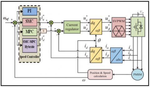
The control structure of the studied drive system is mainly composed of the PMSM supplied by a three-phase inverter controlled through the Space Vector Pulse Width Modulation (SVPWM) strategy, regulators, the direct and quadrature current components, and a speed controller, as illustrated in Figure 1. However, in this work, we consider four types of speed controllers.
Figure 1. Structure of the control system
The electrical and mechanical modeling of the PMSM is carried out in the rotating reference frame (Park reference frame), which simplifies the dynamic equations and facilitates the design of control strategies [14]. This modeling is based on the electrical equations derived from Kirchhoff’s laws and the mechanical equation of rotational dynamics.
2.1 PMSM electrical model
The electrical equations of the PMSM in the dq reference frame are expressed as:
$\left\{\begin{array}{l}\frac{d i_d}{d t}=\frac{1}{L_d}\left(v_d-R_s i_d+\omega_e L_q i_q\right) \\ \frac{d i_q}{d t}=\frac{1}{L_q}\left(v_q-R_s i_q-\omega_e\left(L_d i_d+\phi_f\right)\right)\end{array}\right.$ (1)
where,
id, iq: Stator current components in dq reference (A);
vd, vq: Stator voltage components in dq reference (V);
Rs: Stator resistance (Ω);
Ld, Lq: Inductances along d and q axes (H);
ϕf: Permanent magnet flux linkage (Wb);
ωe: Electrical angular speed (rad/s), related to the mechanical angular speed by:
$\omega_e=p \cdot \omega_m$ (2)
with p being the number of pole pairs.
2.2 Electromagnetic torque
The electromagnetic torque developed by the PMSM is given by the study [15]:
$T_e=\frac{3}{2} p\left[\phi_f i_q+\left(L_d-L_q\right) i_d i_q\right]$ (3)
2.3 Mechanical model of PMSM
The rotational dynamics of the rotor are described by the research [16]:
$J \frac{d \omega_m}{d t}=T_e-T_L-B \omega_m$ (4)
where,
J: Rotor inertia (kg·m²);
ωm: Mechanical angular speed (tr/s);
TL: Load torque (Nm);
B: Viscous friction coefficient (Nm·s).
3.1 Enhanced PI control
The PI controller is one of the most widely used techniques in speed regulation of electric motor drives [17, 18]. It is based on correcting the error between the reference speed and the measured speed using the control law:
$u(t)=K_p \cdot e(t)+K_i \int e(t) d t$ (5)
With,
$e(t)=\omega_{\text {ref }}(t)-\omega(t)$ (6)
where,
$e(t)$: Speed error;
$K_p$: Proportional gain;
$K_i$: Integral gain.
This controller is simple to implement and ensures satisfactory tracking in steady-state operation. However, its performance deteriorates in the presence of fast disturbances, nonlinearities, or motor parameter variations.
Kp and Ki gains were adjusted by the pole placement method and then refined by simulation to the values Kp = 0.05 and Ki = 0.2 giving the desired performance, in particular a better compromise for our system and that the performance remains significant especially by the SMC-MPC hybridization.
3.2 Sliding mode control
The structure of such a controller is shown before in Figure 1. The speed error, which defines the sliding surface (S), is the difference between the reference speed (setpoint) and the measured speed, expressed as studies [19, 20]:
$e(t)=\omega_{\mathrm{ref}}(t)-\omega(t)$ (7)
The sliding surface is mathematically expressed as a combination of the error and its derivative, as follows:
$s(t)=\lambda e(t)+e(t)$ (8)
where, λ is a positive coefficient (λ>0) that determines the convergence speed.
The existence rule of the SMC is S = 0 to ensure that the system reaches the surface of the slip:
$\left\{\begin{array}{l}\lim _{s \rightarrow 0^{-}} S>0 \\ \lim _{s \rightarrow 0^{+}} S<0\end{array}\right.$ (9)
The Lyapunov function is a very used method to study the existence of SMC.
$V(S(\omega))=\frac{1}{2} S^2(\omega)$ (10)
$V(S(\omega))=S(\omega) \cdot S(\omega)$ (11)
With,
$S(\omega)=\omega_{r e f}-\omega$ (12)
By replacing the following dynamic Eq. (13) in the Eq. (11), we obtain the Eq. (14):
$\frac{d \omega}{d t}=\frac{1}{J}\left(T_m-T_{e m}-\beta \cdot \omega\right)$ (13)
$\mathrm{S}(\omega)=\omega_{r e f}+\frac{1}{J}\left(T_{e m}+\beta \cdot \omega-T_m\right)$ (14)
The control law consists of two components: the equivalent term $\left(T_{e m}\right)$, which cancels the system dynamics on the sliding surface, and the switching term $\left(T_{e m_n}\right)$, which drives the system toward the surface, as given by researches [21, 22]:
$T_{e m}=T_{e m_{e q}}+T_{e m_n}$ (15)
Then Eq. (16) becomes:
$\begin{gathered}S(\omega)=\omega_{\text {ref }}+\frac{1}{J}\left(\left(T_{\text {em_eq }}+T_{\text {em_n }}\right)+\beta \cdot \omega\right. \left.-T_m\right)\end{gathered}$ (16)
When the system reaches the sliding surface accordingly it satisfies the linear differential equation $S(\omega)=0, S(\omega)=0$, and $T_{\text {em_n }}=0$, we obtain:
$T_{e m e q}=-J \omega_{r e f}-f \cdot \omega+T_m$ (17)
Replacing the Eq. (17) in Eq. (16) we obtain:
$\mathrm{S}(\omega)=\frac{1}{J}\left(T_{e m_{-} n}\right)$ (18)
To ensure Lyapunov convergence:
$T_{e m_{-} n}=-K \cdot \operatorname{sign}(S(\omega))$ (19)
With K > 0.
3.3 Model predictive control
The model predictive control is a modern, optimization-based approach that predicts the future behavior of the system using a mathematical model and chooses the optimal control action by minimizing a cost function at each sampling instant [23, 24].
Regarding modeling and prediction: the MPC uses a motor model to predict the evolution of speed and current over a finite horizon (N), along with a cost function that minimizes a criterion at each computation step. In addition, an explicit control law, derived for a linearized and unconstrained model, directly computes the current reference as a function of the error and the measured current.
The MPC inherently considers constraints on current and torque by imposing bounds during the optimization process. Its main advantage is the ability to anticipate future events and manage physical limitations. Meanwhile, the MPC strategy used is of the “finite control set” (FCS-MPC) type applied to the linearized model of the PMSM. The control law is computed in discrete time by solving a quadratic program (QP) with prediction horizon Np and control horizon Nc.
The following Eqs. (20) and (21) represent the analytical solution of the unconstrained QP.
$J=\sum_{k=0}^{N-1}\left(Q e_k^2+R i_{q, k}^2\right)$ (20)
where,
ek and iq,k: The predicted error and quadrature current at step k;
Q, R: Positive weighting matrices that balance tracking accuracy and control effort.
The explicit current reference is then computed as:
$i_q^{M P C}=\frac{Q_e-R i_q}{Q+R}$ (21)
Note that Np and Nc were set to 10 and 3 sampling steps, respectively, in order to balance accuracy and computation time.
3.4 Hybrid SMC-MPC control
The objective of the hybridization is to combine the robustness of sliding mode control with the predictive capability of MPC. In the proposed approach, the current references are calculated separately according to the following relations:
$i_q^{M P C}=\frac{Q_e-R i_q}{Q+R}$ (22)
$i_q^{S M C}=K_{S M C} \operatorname{sat}\left(\frac{s}{\beta}\right)$ (23)
where, sat is the saturation function and β > 0 represents the thickness of the boundary layer. This technique, also known as the boundary layer approach, is widely used to mitigate chattering, by introducing a region where the control varies continuously, the frequent switching of the control signal is reduced while maintaining the robustness of sliding mode control [25]. The boundary layer width β must be carefully selected, a small value improves tracking accuracy but allows oscillations to persist, whereas a larger value reduces oscillations at the cost of a slight increase in tracking error.
The objective of the hybridization is to take advantage of the robustness of SMC while benefiting from the anticipation and constraint handling capabilities of MPC [26, 27]. Specifically, at each computation step, two quadrature current references are determined separately:
$i_q^{\text {hybride }}=(1-\alpha) i_q^{M P C}+\alpha i_q^{S M C}$ (24)
With α∈[0,1].
However, a coefficient α close to « 0 » favors the smoothness and anticipatory capability of MPC, while a value close to « 1 » enhances the robustness of SMC. The value of α was selected through a sensitivity analysis within the interval [0, 1], by minimizing the root mean square error (RMSE) over the driving cycle.
The results show that performance deteriorates for α < 0.3 (control too discontinuous) and for α > 0.7 (slower dynamics), while α = 0.5 provides the best trade-off in terms of RMSE and current signal smoothness.
The complete driving cycle simulation was performed for a total duration of 50 seconds, enabling the computation of quantitative indicators for each control strategy (Enhanced PI, SMC, MPC, and Hybrid SMC-MPC). The performance metrics selected in this work are studies [28-30]: the Root Mean Square Error (RMSE), the Integral of Absolute Error (IAE), and the maximum overshoot during transitions, defined as Max(vact(t)−vref(t)). RMSE and IAE are respectively expressed by the following mathematical relations:
$\sqrt{\frac{1}{T} \int_0^T e(t)^2 d t}$ (25)
$\int_0^T|e(t)| d t$ (26)
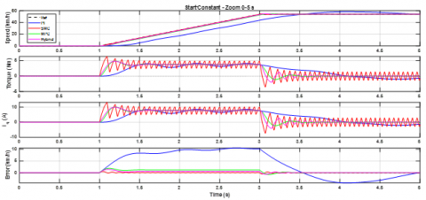
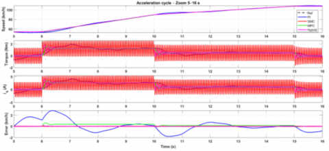
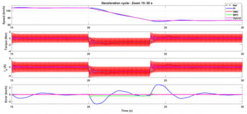
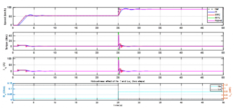
Figure 2 illustrates the system behavior in terms of speed, torque, stator quadrature current, and tracking error for the four considered control strategies. In addition, Figure 3(a), (b) and (c) provide zoomed views of three main operating scenarios. Specifically, Figure 3(a) shows the first five seconds (0→ 5 s), where the vehicle starts from rest and accelerates to 50 km/h. Figure 3(b) presents the interval (5 s→ 16 s), covering a deceleration between 20 and 24 s followed by a constant-speed phase from 24 to 30s. Figure 3(c) highlights the interval (15 s→ 30 s), corresponding to a deceleration phase until steady-state operation at constant speed. Finally, the last zoom (30s→ 50s) illustrates three deceleration phases (30→35 s, 35→40 s, and 40→42 s), leading to the vehicle stop at 42s.
Figure 2. Full driving cycle
(a) Zoom start_constant phase
(b) Zoom on acceleration phase
(c) Zoom deceleration phase
(d) Zoom stop phase
Figure 3. Zoomed views of driving scenarios
The analysis of these results shows that:
The performance indicators for the four controllers are summarized in Table 1.
Table 1. Performance comparison
|
Strategy |
RMSE |
IAE |
Overshoot |
|
PI |
2,12 |
51,79 |
4,33 |
|
SMC |
0,06 |
2,67 |
0,55 |
|
MPC |
0,32 |
9,49 |
0,73 |
|
SMC-MPC |
0,13 |
1,70 |
0,68 |
The quantitative comparison shows that the proposed hybrid method significantly improves tracking performance compared to the other strategies. PI remains insufficient for full driving-cycle operation. SMC achieves remarkable accuracy but at the expense of undesirable oscillations. MPC provides a good compromise between speed and accuracy, thanks to its predictive capability. Finally, the hybrid SMC-MPC approach further reduces tracking error while smoothing the control effort, offering superior robustness and driving comfort.
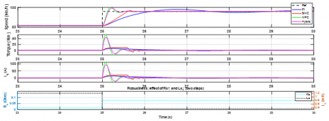
The robustness test consists of applying a ramp from 0 to 15 m/s within 0-3 s, followed by maintaining the speed at 15 m/s until 25 s. At this instant, two events occur simultaneously, the reference abruptly changes to 25 m/s (≈90 km/h), and the motor electrical parameters are modified (Rs multiplied by 5 and Ls reduced to 30%). This reduces the electrical time constant τe = Ls/Rs by a factor of five. The four controllers are simulated under both nominal and perturbed conditions and the simulation results are illustrated in Figures 4 and 5.
The values below are estimates based on the observation of the curves. They indicate the maximum overshoot relative to the final plateau (90 km/h), the rise time (10% → 90% of the step), and the settling time required for the response to remain within ±2 km/h around the final reference.
The electrical time constant τe=Ls/Rs dictates the speed of the current loop. By multiplying Rs by 5 and reducing Ls to one-third, τe is reduced by a factor of five. This accelerates the current response and, consequently, the speed response, resulting in slightly higher overshoot for PI and SMC.
However, the mechanical dynamics of the vehicle (large inertia J) dominate the overall behavior: parameter variations affect speed only during rapid transients.
Figure 4. Robustness: Effect of Rs ↑ and Ls
Figure 5. Zoom effect of Rs ↑ and Ls ↓ phase
In real world applications, variations in resistance and inductance may result from motor heating or aging. The simulations demonstrate that predictive and hybrid strategies are better suited to maintaining performance and driving comfort under such conditions. Pure SMC requires additional chattering mitigation techniques to avoid excessive mechanical stress, while PI may need recalibration to reduce sensitivity to uncertainties. Table 2 presents the metrics and their discussion.
Table 2. Robustness comparaison
|
Controller |
Overs-Hoot |
Rise Time (s) |
Settling Time (s) |
Sensitivity to Variations in Rs, Ls |
|
PI (nominal) |
~10 |
~1.5 |
~5.0 |
Sensitive: overshoot increases as τe decreases, since the current integrator reacts faster. |
|
PI (perturbed) |
~9 |
~1.3 |
~4.5 |
Increasing Rs and decreasing Ls reduce τe, accelerating the response and causing slightly higher overshoot. |
|
SMC (nominal) |
~20 |
~0.8 |
~3.0 |
Very sensitive: sliding control reacts abruptly to setpoint changes; reduced τe amplifies chattering. |
|
SMC (perturbed) |
~25 |
~0.6 |
~2.5 |
Torque and current oscillations become faster and more pronounced; robustness is degraded by switching. |
|
MPC (nominal) |
~5 |
~1.2 |
~4.0 |
Robust: MPC anticipates the new setpoint and modulates the control effort; electrical parameter variations have marginal effect. |
|
MPC (perturbed) |
~5 |
~1.1 |
~3.8 |
Predictive capability allows similar tracking despite reduced τe\tau_e. |
|
Hybrid (nominal) |
~6 |
~1.1 |
~4.0 |
Very robust: the MPC–SMC combination damps oscillations while preserving MPC-like rapidity. |
|
Hybrid (perturbed) |
~6 |
~1.0 |
~3.7 |
Hybridization absorbs parameter variations and maintains almost identical dynamics. |
The proposed hybrid SMC-MPC approach combines the robustness of SMC against uncertainties with the predictive capability of MPC. By weighting the contributions through a progressive saturation term, it significantly reduces oscillations though not completely while minimizing the IAE (≈ 1.7) and limiting overshoot (< 1%). This method provides an optimal compromise between dynamic performance and control smoothness, ensuring precise speed tracking while respecting constraints and improving driving comfort.
The analysis shows that the hybrid controller is particularly well suited to electric vehicles, where accurate speed tracking and effective constraint management are crucial.
For future work, experimental validation will be required, including the evaluation of these strategies on a test bench and the integration of thermal and energy models. Extending this approach to multiphase topologies and real time embedded implementation will further confirm the advantages of this strategy, particularly its robustness to parameter variations and its ability to offer the best compromise between response speed, tracking accuracy, and disturbance rejection.
|
id, iq |
stator current components in dq reference (A) |
|
vd,vq |
stator voltage components in dq reference |
|
Rs |
stator resistance (Ω) |
|
Ld, Lq |
inductances along d and q axes (H) |
|
ϕf |
permanent magnet flux linkage (Wb) |
|
ωe |
electrical angular speed (rad/s) |
|
p |
number of pole pairs |
|
J |
rotor inertia (kg·m²) |
|
ωm |
mechanical angular speed (tr/s) |
|
TL |
load torque (N·m) |
|
B |
viscous friction coefficient (N·m·s) |
|
Te |
electromagnetic torque (N·m) |
|
e(t) |
speed error |
|
Kp |
proportional gain |
|
Ki |
integral gain |
|
λ |
convergence speed |
|
S |
surface of the slip |
|
$\begin{aligned} & T_{e m} \_e q \\ & T_{e m} \_n\end{aligned}$ |
system dynamics on the sliding surface system toward the surface |
[1] Ghanayem, H., Alathamneh, M., Nelms, R.M. (2024). PMSM field-oriented control with independent speed and flux controllers for continuous operation under open-circuit fault at light load conditions. Energies, 17(3): 593. https://doi.org/10.3390/en17030593
[2] Li, T., Sun, X.D., Lei, G., Yang, Z.B., Guo, Y.G., Zhu, J.G. (2022). Finite-control-set model predictive control of permanent magnet synchronous motor drive systems an overview. IEEE/CAA Journal of Automatica Sinica, 9(12): 20872105. https://doi.org/10.1109/JAS.2022.105851
[3] Zhang, Y., Jin, J., Huang, L. (2020). Model-free predictive current control of PMSM drives based on extended state observer using ultralocal model. IEEE Transactions on Industrial Electronics, 68(2): 993-1003. https://doi.org/10.1109/TIE.2020.2970660
[4] Wang, B., Feng, X., Wang, R. (2023). Open-circuit fault diagnosis for permanent magnet synchronous motor drives based on voltage residual analysis. Energies, 16(15): 5722. https://doi.org/10.3390/en16155722
[5] Merabet, H., Bahi, T. (2017). Fuzzy monitoring of stator and rotor winding faults for DFIG used in wind energy conversion system. International Journal of Modelling, Identification and Control, 27(1): 49-57. https://doi.org/10.1504/IJMIC.2017.082485
[6] Chai, F., Gao, L., Yu, Y., Liu, Y. (2019). Fault-tolerant control of modular permanent magnet synchronous motor under open-circuit faults. IEEE Access, 7: 154008-154017. https://doi.org/10.1109/ACCESS.2019.2948363
[7] Ghanayem, H., Alathamneh, M., Nelms, R.M. (2023). Decoupled speed and flux control of a three-phase permanent magnet synchronous motor under an open-circuit fault using a PR current Controller. Energies, 16(14): 5325. https://doi.org/10.3390/ en16145325
[8] Mamashli, M., Jamil, M. (2024). Model predictive currentcontrol combined sliding mode control for flux switch permanent magnet machine drive system. In IECON 2024-50th Annual Conference of the IEEE Industrial Electronics Society, Chicago, USA, pp. 1-6. https://doi.org/10.1109/IECON55916.2024.10905480
[9] Ding, J., Jiao, X., Zhang, J. (2024). Robust adaptive control for hybrid electric vehicles using sliding mode control. Proceedings of the Institution of Mechanical Engineers, Part I: Journal of Systems and Control Engineering, 238(2): 272287. https://doi.org/10.1177/09596518231188496
[10] Bogdan, C., Marian, G., Răzvan, Ș., Cristinel. (2024). Model predictive speed control of Permanent Magnet Synchronous Motor. International Conference on Optimization of Electrical and Electronic Equipment. https://api.semanticscholar.org/CorpusID:33906845.
[11] Zhang, Y., Jin, J., Huang, L. (2021). Model-free predictive current control of PMSM drives based on extended state observer using Ultralocal model. IEEE Transactions on Industrial Electronics, 68(5): 993-1003. https://doi.org/10.1109/TIE.2020.3027227
[12] Dahnoun, I., Bourek, A., Ammar, A., Belaroussi, O. (2024). Active disturbance rejection control based sensorless model predictive control for PMSM. Journal Européen des Systèmes Automatisés, 57(1): 117-125. https://doi.org/10.18280/jesa.570112
[13] Yuan, X., Zuo, Y, Fan, Y., Lee, CH. (2021). Model-free predictive current control of SPMSM drives using extended state observer. IEEE Transactions on Industrial Electronics. https://doi.org/10.1109/TIE.2021.3095816
[14] Wentao, H., Jiachen, D; Wei, H., Wenzhou, L., Kaitao, B.,Yixin, Z. (2021). Current-based open-circuit fault Diagnosis for PMSM drives with model predictive control. IEEE Transactions on Power Electronics, 36(9): 10695-10704, https://doi.org/10.1109/TPEL.2021.3061448
[15] Lekhchine, S., Bahi, T., Soufi, Y. (2013). Direct torque control for double star induction motor. International Journal of Renewable Energy Research, 3(1): 121-125. https://dergipark.org.tr/en/pub/ijrer/issue/16080/168280.
[16] Izgheche, Y., Bahi, T., Lakhdara, A. (2024). Intelligent power management control for hybrid wind solar battery systems connected to micro-grids. Journal Européen des Systèmes Automatisés, 57(4): 1225-1233. https://doi.org/10.18280/jesa.570429
[17] Sangeetha, E., Ramachandran, V.P. (2024). An enhanced proportional resonance controller design for the PMSM based electric vehicle drive system. Heliyon, 10(15): e35244. https://doi.org/10.1016/j.heliyon.2024.e35244
[18] Boukadoum, A., Bahi, T., Oudina, S., Lekhchine, S. (2012). Fuzzy control adaptive of a matrix converter for harmonic compensation caused by nonlinear loads. EnergyProcedia, 18: 715723. https://doi.org/10.1016/j.egypro.2012.05.087
[19] Lakhdara, A., Bahi, T., Moussaoui, A. (2020). Sliding mode control of doubly-fed induction generator in wind energy conversion system. In 2020 8th International Conference on Smart Grid (icSmartGrid), Paris, France, p. 96100. https://doi.org/10.1109/icSmartGrid49881.2020.9144778
[20] Zhou, W., Song, Z., Xiao, X., Guo, Y., Mo, Y. (2024). Sliding mode speed control for PMSM based on model predictive current. Electronics, 13(13): 2561. https://doi.org/10.3390/electronics13132561
[21] Kadhim, N.N., Abood, L.H., Mohammed, Y.A. (2023). Design an optimal fractional order PID controller for speed control of electric vehicle. Journal Européen des Systèmes Automatisés, 56(5): 735-741. https://doi.org/10.18280/jesa.560503
[22] Ullah, K., Guzinski, J., Mirza, A.F. (2022). Critical review on robust speed control techniques for permanent magnet synchronous motor (PMSM) speed regulation. Energies, 15(3): 1235. https://doi.org/10.3390/en15031235
[23] Sehab, R., Akrad, A., Saadi, Y. (2023). Super-twisting sliding mode control to improve performances and robustness of a switched reluctance machine for an electric vehicle drivetrain application. Energies, 16(7): 3212. https://doi.org/10.3390/en16073212
[24] Rodriguez, J., Pontt, J., Silva, C.A., Correa, P., Lezana, P., Cortés, P., Ammann, U. (2007). Predictive current control of a voltage source inverter. IEEE Transactions on Industrial Electronics, 54(1): 495-503. https://doi.org/10.1109/TIE.2006.888802
[25] Davari, Ahmed,A.A., Kim, J.S., Lee,Y.I. (2016). Model predictive torque control of PMSM for EV drives: A comparative study of finite control set and predictive dead-beat control schemes, Eighteenth International Middle East Power Systems Conference (MEPCON), Cairo, Egypt, 2016, pp. 156-163, https://doi.org/10.1109/MEPCON.2016.7836885.
[26] Wu, L., Liu, J., Vazquez, S., Mazumder, S.K. (2021). Sliding mode control in power converters and drives: A review. IEEE/CAA Journal of Automatica Sinica, 9(3): 392-406. https://doi.org/10.1109/JAS.2021.1004380
[27] Wang, Y., Chen, W., Tomizuka, M., Alsuwaidan, B.N. (2013). Model predictive sliding mode control: For constraint satisfaction and robustness. In Dynamic Systems and Control Conference, Palo Alto, USA, 56147: V003T44A005. https://doi.org/10.1115/DSCC2013-4067
[28] Bahi, A., Gasmi, I., Sassi, B.E.N.T.R.A.D. (2023). Study the Impact of Homomorphic Encryption on the Accuracy of Recommendation Systems in E-commerce.
[29] Bahi, A., Ourici, A. (2025). Can we move freely in NEOM's the line? An agent-based simulation of human mobility in a futuristic smart city. arXiv preprint arXiv:2507.15143. https://doi.org/10.48550/arXiv.2507.15143
[30] Soon, C.C., Ghazali, R., Chong, S.H., Shern, C.M., Sam, Y.M., Has, Z. (2020). Efficiency and performance of optimized robust controllers in hydraulic system. International Journal of Advanced Computer Science andApplications, 11(6): 385391. http://doi.org/10.14569/IJACSA.2020.0110650