Ahid Zuhair Hamoodi![]() | Thamer H. Alhussein
| Thamer H. Alhussein![]() | Mustafa Shareef Zewair
| Mustafa Shareef Zewair![]() | Kadhim Z. Naser*
| Kadhim Z. Naser*![]()
© 2025 The authors. This article is published by IIETA and is licensed under the CC BY 4.0 license (http://creativecommons.org/licenses/by/4.0/).
OPEN ACCESS
This research explores the structural response of reinforced concrete beams (RCBs) enhanced with steel fibers (SFs), focusing on both mechanical strength and flexural behavior. The investigation examined how variations in fiber geometry and dosage affect performance under flexural loads. A series of seven beam specimens, each 20 cm wide, 25 cm deep, and 1.5 m long, were subjected to four-point bending tests. The fibers used included straight, hooked-end, and corrugated types, incorporated at different volumetric ratios. The study also assesses the adequacy of current code predictions in comparison with experimental results. Notably, beams containing hooked-end fibers at a 1% volume fraction demonstrated the greatest performance gains. Specifically, specimens with 3 cm and 5 cm hooked-end fibers exhibited increases in ultimate load capacity of 12.05% and 13.64%, respectively, while deflection capacity increased by 137.83% and 140.73%. The findings reveal that the addition of hooked-end fibers significantly improves flexural strength and ductility. However, existing design models were found to substantially underestimate the ultimate moment capacity. The ACI code predictions were approximately 45% lower, and those of EC2 were about 50% lower than the experimental results. These outcomes indicate the necessity for revision in current design practices to more accurately represent the behavior of steel fiber-reinforced concrete.
steel fibers, volume content, flexural stiffness, cracking behavior, ductility, toughness
Concrete that contains short, arbitrarily oriented fibers is known as Fibrous concrete. The main advantage of fibers is the providing of post-cracking tension resistance to the concrete [1-5]. In reinforced concrete structures, cement is a major component, but cement-based material will crack under tensile loading. The remaining strength still exists in RC members before failure, while micro-cracking happens. This problem can be controlled by using fibers. Consequently, numerous researchers have explored the incorporation of steel and plastic fibers into various structural elements and have systematically analyzed their influence on the mechanical properties of these components [6-12]. The spread of cracks can be governed, their initiation can be obstructed, and their width can be reduced by using fibers, as well as, the durability of concrete can be enhanced. Also, concrete's compressive, tensile, and torsion strength can be improved using steel fibers (SFs) [13, 14].
Many researchers investigate the role of steel fibers in the shear and flexural behavior of reinforced concrete (RC) columns and beams. Practically steel fibers reinforced concrete (SFRC) is widely applied in precast tunnel segments, industrial pavements, and slabs [15-19]. Substantial increases in tensile and flexural capacity of SFRC components are generally unachievable with low to medium steel fiber volume fractions. The energy dissipation and toughness in SFRC members can be enhanced using SF [15-19]. Additionally, high SF volume content can increase the tensile strength, Pre-cracking strain-hardening and post-cracking rigidity [20].
Previous studies have thoroughly investigated how SFRC beams respond to four-point bending. According to these tests, Hussain et al. [21] proved that the flexural capacity of RC two-way slabs was improved by 13%, 19%, and 39% for slabs with corrugated SF, polyolefin fiber and hooked end SF, respectively. Whereas, the polyolefin fiber slightly upgrades Concrete’s response to mechanical stress. Abdullah et al. [22] investigate the ability of shape and type of fibers (straight SF, corrugated SF, hooked SF and polyolefin fibers) on the torsional behavior of solid and hollow RC beams. A significant improvement in the torsional capacity was noticed for the beams with corrugated SF, while, the straight SF and polyolefin fibers showed a negligible enhancement in the load-bearing performance and slight improvement in the twisting capacity. However, the polyolefin fibers showed greater capability in improving the twisting deformation capacity of RC beams relative to other types. Altun et al. [23] conducted a laboratory investigation on the demeanor of SFRC BEAMS in flexure; the results showed unimportant enhancement in maximum moment ability and significant improvement in flexural toughness. Hamoodi et al. [24] studied the shear behavior of SFRC beams and exhibited enhanced resistance to shear forces with enormously tiny diagonal cracks of SFRC beams without stirrups to that of RCB with stirrups. At the same time, the existing universal codes underestimated contribution of the concrete matrix to shear performance. Zewair et al. [25] experimented the shear behavior of SFRC deep beams with and without opening. The study showed that the SF enhanced both crack and ultimate loads. Moreover, the use of SF was more effective in strengthening load at which the first crack appeared in beams with openings, while a significant improvement in the maximum load was mentioned for beams without opening. Abbas et al. [26] studied the effect of polyolefin fibers volume fractions on the shear and flexural behavior of RC flat slabs with and without opening. The shear and flexural strengths were increased as the volume content of fibers increased. Slabs with hole recorded large deflection comparing the specimens without hole. All slabs in shear showed a punching failure. Numerical results showed excellent agreement with experimental tests regarding the strength and stiffness of slabs.
Most previous studies have focused on the influence of steel fibers on the properties of concrete mixtures and the behavior of various reinforced concrete elements. This has been approached either by investigating different fiber types at a single volume fraction, as in studies [21, 22], or by examining a single fiber type at varying volume fractions, as in studies [23, 26], which assessed their impact on the structural characteristics of concrete and the bending performance of reinforced concrete beams and slabs. It is worth noting that study [24], for example, explored the combined effect of different fiber types and volume fractions on both the structural characteristics and shear performance of RC beams. However, many other studies have remained limited to evaluating impact of different fiber types and proportions on concrete’s mechanical behavior only, without addressing their influence on the structural behavior of reinforced concrete elements. Therefore, this study aims to bridge this research gap through a comprehensive comparison of the effects of various steel fiber types (straight, hooked, and corrugated) and their varying volume fractions (0%, 0.5%, 1% and 1.5%) on both the mechanical properties of concrete and the flexural performance of reinforced concrete beams. Furthermore, 1% SF's volume content was adopted to investigate the effect of straight, hooked end in two lengths (3 cm and 5 cm), and corrugated SFs.
Straight, hooked (3 cm and 5 cm), and Corrugated SF were used to examine their influence on the concrete’s performance under compression, tension (via splitting), and flexure. At the same time, four reinforced concrete beams (RCBs), each with straight SF and three RCB with 3 cm hooked end, 5 cm hooked end, and corrugated SF, were manufactured and tested to reveal the contribution of the volumetric ratio and types of SF on the flexural behavior.
2.1 Samples and specimen’s details
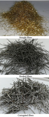
The effect of straight SF with four-volume ratios (0%, 0.5%, 1%, and 1.5%) (to ensure uniform fibre dispersion and workable concrete mixes), and the effect hooked end SF in two lengths (3 cm and 5 cm), and corrugated SF at (1% volume fraction) (Figure 1) on the ability of concrete to withstand compressive, tensile (splitting), and flexural stresses was investigated.
Figure 1. Types of SF
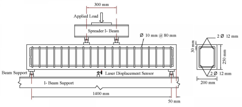
For each SF's ratio, three cubes, three cylinders and three prisms as per BS EN 12390-3-2019 [27], ASTM C496/C496M-17 [28], and ASTM C78/C78M [29], respectively, were tested at 28 days. The total length, width, and overall depth of each SFRC beam were 1500 mm, 200 mm, and 250 mm, respectively. Seven beams were cast and tested, four of them to reveal the influence of straight SF's ratios (0%, 0.5%, 1%, and 1.5%) on the flexural behavior, and three beams to explore the effect of SF's types [ (3 cm and 5 cm) hooked and corrugated] on the flexural behavior at 1% volume content. Table 1 and Figure 2 present the specifications, structural configuration and reinforcement details of the tested beams. Tables 2 and 3 show the test results and details of the steel reinforcement and SF, respectively.
Table 1. Beams characteristics
|
Beams No. |
Dimensions (mm) [L×W×D] |
SF Type |
SF Volume Content (%) |
|
F1 |
1500 × 200 × 250 |
- |
0 |
|
F2 |
Straight |
0.5 |
|
|
F3 |
Straight |
1.0 |
|
|
F4 |
Straight |
1.5 |
|
|
F5 |
3 cm Hooked |
1.0 |
|
|
F6 |
5 cm Hooked |
1.0 |
|
|
F7 |
Corrugated |
1.0 |
Table 2. Test results of reinforcing steel bars
|
Bars Diameter [mm] |
fy [MPa] |
fu [MPa] |
|
10 |
476 |
592 |
|
12 |
522 |
671 |
Table 3. Details of steel fibers (by supplier)
|
Type of Fibres |
Density [kg/m3] |
Tensile Strength [MPa] |
Length [mm] |
Diameter [mm] |
Aspect Ratio [l/d] |
Modulus of Elasticity [MPa] |
|
Straight |
7860 |
2850 |
12 |
0.25 |
50 |
2×10⁵ |
|
Hooked [3 cm] (Hooked ends and straight middle) |
7860 |
≥ 1000 |
30 |
0.5 |
60 |
2×10⁵ |
|
Hooked [5 cm] (Hooked ends and straight middle) |
7860 |
≥ 1000 |
50 |
0.75 |
66 |
2×10⁵ |
|
Corrugated |
7860 |
≥ 700 |
30 |
0.55 (Equivalent Dia.) |
55 |
2×10⁵ |
(a)
(b)
Figure 2. Geometry, reinforcement details and experiment assembly of beams
2.2 Details of concrete mix
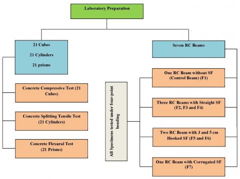
Local materials and SF were mixed to produce 7 SFRC BEAMS, 21 SFC cubes (150 × 150 × 150 mm), 21 SFC cylinders (150 mm dia. × 300 mm height), and 21 SFC prisms (100 × 100 × 350 mm) to study load-bearing properties in compression, split-tension, and bending (Figure 3). During the mixing process, the steel fibers were added gradually to ensure proper distribution within the mix and to prevent clumping. The mixes were closely monitored throughout the mixing, transportation, and placement into the molds and forms, and no fiber clumping or balling was observed. Table 4 details the compositions of the concrete mix.
Figure 3. Details of laboratory program
Table 4. Concrete mix compositions
|
Gravel [kg/m3] |
Sand [kg/m3] |
Cement [kg/m3] |
Water [kg/m3] |
Super Plasticizer [kg/m3] |
SF [kg/m3] |
|||
|
0% |
0.5% |
1.0% |
1.5% |
|||||
|
1110 |
740 |
370 |
181.3 |
2.22 |
0 |
12 |
24 |
36 |
Figure 4. Activities of concrete casting
Concrete was poured into the forms (beams) and molds (cubes, cylinders, and prisms) after the mixing was finished and compacted mechanically using a standard poker vibrator. Figure 4 summarizes the mixing and casting steps by photos.
2.3 Test set-up of beams
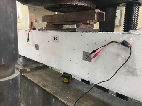
The flexural behavior of seven simply supported RCB and SFRC BEAMS was studied concerning cracking behavior, load carrying capabilities, failure mode, and load-deflection relation, by applying four-point loading test (using 300mm apart of two-points line loads). Beams test set-up specifics are illustrated in Figure 2.
Torsee hydraulic UTM rated for 2000 kN loading capacity was used to test beams. The first crack load, the ultimate load, crack width, and deflections were noticed and recorded during loading. A laser displacement sensor was positioned under the bottom face at the midpoint of the tested beam to capture deflection during loading, as shown in Figure 2. A digital gauge testing device (Model CK-102) by HFBTE was adopted to gauge the crack width.
Main reinforcing bars, 12 mm in diameter, were installed along the top and bottom. On the other hand, 10 mm diameter steel bars were involved as stirrups reinforcement at 80 mm c/c along the entire beam length, as shown in Figure 2. The cylinders, cubes, and related beams were tested at the same time.
3.1 Mechanical characteristics
Superplasticizer was incorporated in all concrete mixes to hold the reduction in workability caused by SF. The workability of normal concrete (without SF) was 21.5 cm, while it became 15.5 cm, 7.5 cm, and 2.5 cm for mixes with 0.5%, 1.0%, and 1.5% straight SF, respectively. Similarly, for mixes with 3 cm hooked, 5 cm hooked, and corrugated SF, the workability was 11 cm, 12 cm, and 10 cm, respectively. Accordingly, the workability of the fresh concrete is highly affected by the addition of SF. This reduction in workability was due to increased friction between diverse constituents resulting from using SF. The similar effect was obtained in literature [24, 30]. For field applications, the use of high-range water reducers, gradual and even fiber addition, optimization of the mixing sequence and time, adjustment of aggregate grading and proportions, monitoring and controlling fiber volume, application of proper vibration and placement techniques, and consideration of alternative fiber types and geometries represent several practical solutions and strategies to overcome the reduction in workability of concrete with higher steel fiber volume fractions.
Table 5. Beams details and mechanical properties of RC and SFRC mixes
|
Details of Beams |
Average 28-Days Cube Compressive Strength* (MPa) |
Average 28-Days Splitting Tensile Strength* (MPa) |
Average 28-Days Modulus of Rupture* (MPa) |
|||||
|
Beam No. |
a/d |
SF Type |
Aspect Ratio |
Main Reinf. Ratio (%) |
SF Volume Fraction (%) |
|||
|
F1 |
2.696 |
- |
- |
0.554 |
0 |
35.6 |
2.29 |
4.19 |
|
F2 |
2.696 |
Straight |
50 |
0.554 |
0.5 |
39.3 |
2.85 |
5.49 |
|
F3 |
2.696 |
Straight |
50 |
0.554 |
1.0 |
44.8 |
3.75 |
7.0 |
|
F4 |
2.696 |
Straight |
50 |
0.554 |
1.5 |
47.1 |
4.37 |
7.65 |
|
F5 |
2.696 |
3 cm hooked |
60 |
0.554 |
1.0 |
43.5 |
4.30 |
8.14 |
|
F6 |
2.696 |
5 cm hooked |
66 |
0.554 |
1.0 |
42.1 |
4.57 |
8.20 |
|
F7 |
2.696 |
Corrugated |
55 |
0.554 |
1.0 |
44.0 |
4.16 |
7.78 |
* Average of three samples.
Compressive strength, splitting tensile strength, and modulus of rupture are listed in Table 5, the results are the average of three samples. The Bridging effect of SF, which restricts the creation and dissemination of cracks in the concrete, leads to improve the mechanical properties of conventional concrete. The laboratory compressive strength of normal concrete was 35.6 MPa, and it was slightly increased by adding SF. The 1.5% volume fraction of straight SF showed the more significant improvement in compressive, tensile (splitting), and flexural strength characteristics by 32.3%, 90.8%, and 82.6%, respectively. Also, for a 1.0% volume fraction, the straight SF included a significant increase in compressive strength by 25.8% compared with hooked and corrugated SF. This may be attributed to the homogeneous dispersion of the 12 mm length straight micro steel fibers in addition to their bridging effect. Also, for 1.0% volume fraction, the use of 5 cm hooked SF resulted in a tremendous increase in split tensile strength and flexural strength by 99.6% and 95.7%, respectively, compared with straight, 3 cm hooked, and corrugated SF. Accordingly, as the aspect ratio (l/d= 66 for 5 cm hooked) increase, the restriction of cracks formation and propagation increase. Generally, all specimens which contain SF showed a ductile behavior till failure compared with normal concrete specimens. Similar outcomes were obtained in the previous works [17, 31].
3.2 Impact of steel fibers on the bending performance of RCBs
3.2.1 Ultimate load and deflection
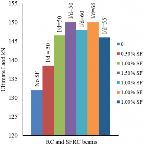
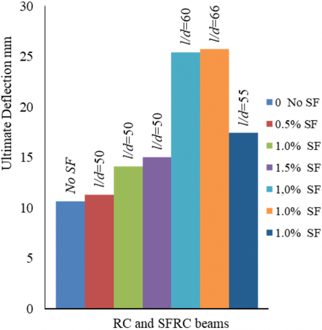
Table 6 compares the highest load and corresponding deflection of RCB and SFRC BEAMS. Figures 5 and 6 show the SFs volume and type effect on the Max. load capacity and peak deflection, respectively. Both graphs show that increasing the volume fraction and aspect ratio of steel fibers leads to higher peak load capacity and greater maximum deflection.
The ultimate load of all SFRC BEAMS is slightly greater than the accompanying RCB, as shown in Table 6. It is clear that the enhancement of the ultimate load of SFRC BEAMS increased with increasing straight SF's volume content, and it was 4.92%, 10.98%, and 13.64% for F2, F3, and F4 SFRC BEAMS, respectively. On the other hand, for 1% SF volume content, the 5 cm hooked SFRC BEAMS shows the highest increase in maximum load compared to other SF types, in this case, the enhancement of the ultimate load was 10.98%, 12.05%, 13.64%, 10.61% for F3, F5, F6 and F7 SFRC BEAMS respectively.
Table 6. Laboratory load and deflection values
|
Beam No. (Steel Fiber Volume Content) |
At Cracking |
At Ultimate |
Failure Mode |
||||
|
Load [kN] |
Load Increasing Ratio (%) |
Deflection [mm] |
Load [kN] |
Load Increasing Ratio (%) |
Deflection [mm] |
||
|
F1 (0) |
36 |
- |
0.52 |
132 |
- |
10.68 |
Flexural |
|
F2 (0.5%) |
41 |
13.88 |
0.61 |
138.5 |
4.92 |
11.31 |
Flexural |
|
F3 (1.0%) |
44.5 |
23.61 |
0.75 |
146.5 |
10.98 |
14.14 |
Flexural |
|
F4 (1.5%) |
48.9 |
35.83 |
0.88 |
150 |
13.64 |
15.06 |
Flexural |
|
F5 (1.0%) |
58.0 |
61.11 |
1.60 |
147.9 |
12.05 |
25.4 |
Flexural |
|
F6 (1.0%) |
65.0 |
80.56 |
1.20 |
150 |
13.64 |
25.71 |
Flexural |
|
F7 (1.0%) |
45.0 |
25.0 |
0.95 |
146 |
10.61 |
17.42 |
Flexural |
Also, the present results designate that the ultimate deflection for all SFRC BEAMS was greater than that of the RCB. The ultimate deflection of F2, F3, and F4 SFRC BEAMS was 5.89%, 32.4%, and 41.01%, respectively larger than that of F1. Furthermore, at 1.0% SF volume content, ultimate deflection increased by 32.4%, 137.83%, 140.73%, and 63.11% for F3, F5, F6 and F7 SFRC BEAMS, respectively. Similar findings were obtained in the literature [17, 23].
The above results also reflect the influence of the aspect ratio, where an increase in this ratio enhances the flexural behavior of reinforced concrete beams containing steel fibers. The findings indicate that, at the same volume fraction, 5 cm hooked end SFs (l/d = 66) demonstrated superior performance in terms of mechanical properties, cracking load, and ultimate load, compared to straight SFs, corrugated SFs, and 3 cm hooked end SFs having l/d of 50, 55, and 60, respectively, as illustrated in Figures 5 and 6.
Figure 5. Influence of SFs on ultimate load
Figure 6. Influence of SFs on ultimate deflection
Accordingly, for all tested SFRC BEAMS, the ultimate load was slightly enhanced compared with the considerable improvement in flexural stiffness (upgrading of maximum deflection) due to a slight enhancement in the concrete compressive strength, as illustrated in Table 5.
3.2.2 load-deflection behavior
The inclusion of steel fibers improved the bending rigidity of the tested specimens due to the stitching effect of fibers, which restricts the onset and development of cracking [32, 33].
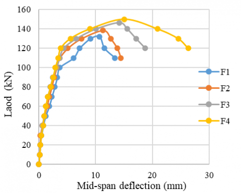
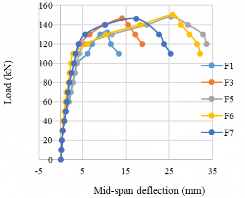
Figure 7 presents the midspan deflection curves of all tested beams with various SF's volume content and types at every loading stage. For RCB and SFRC BEAMS, the midspan deflection curves begin with a straight line till the appearance of the first crack. A gradual reduction in the curve’s gradient occurs after the first crack load, accompanied by more developed cracks. As the applied load increases, a considerable reduction in the slope of the midspan deflection curves occurs after the yielding of the main steel reinforcement. At this stage, any increase in applied load causes high deformations till the ultimate load (crushing of concrete).
(a)
(b)
Figure 7. Load-midspan deflection beahviour: (a) influence of fibers content, (b) influence of fibers type
For straight SFRC BEAMS (beams F2 to F4), the flexural stiffness was enhanced with increasing SF's volume content, as shown in Figure 7(a), in agreement with earlier research findings [16, 33]. This enhancement is due to the bridging ability of fibers, which create resistance to crack surface tensile stress [23]. Before the failure, SFRC BEAMS with 0.5%, 1%, and 1.5% straight SF show additional crack restriction, superior flexural stiffness, and more considerable ultimate deflection.
Similarly, the flexural stiffness developed employing hooked and corrugated steel fibers. As shown in Table 6 and Figure 7(b), the 3 cm and 5 cm hooked SFRC BEAMS have the highest flexural stiffness before failure compared with straight and corrugated SFRC BEAMS.
3.2.3 Cracking behavior
In the present study, the first crack load was effectively enhanced by using SF, which delays the appearance of the first crack and hence increases the first crack load, as shown in Table 6. It can be observed that this enhancement increased with increasing SF's volume content, and the first crack load of beam F4 increased by 35.83% compared with F1. Similarly, the 3 cm and 5 cm hooked SFRC BEAMS (F5 and F6) have 61.11% and 80.65% increasing in first crack load respectively compared with F1. These results confirm previous investigations, in which SF effectively enhance the first cracking load and slightly affect the ultimate load [21, 26, 32].
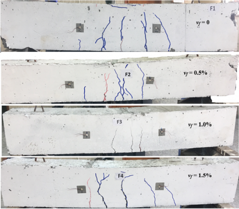
The flexural test results are listed below in Table 7 for both cracking and failure stages. Figure 8 shows impact of the volume percentage of fibers on the crack pattern of RCB and SFRC BEAMS. The cracking behavior for different types of fibers is illustrated in Figure 9.
At first, narrow cracks developed in the region between the two applied loads. A similar crack pattern was observed with increasing fibers content, as shown in Figure 8. The cracks are concentrated within the loading area for RCB and SFRC BEAMS. However, approximately a few cracks of uniform width appeared for RCB and SFRC BEAMS with fibers volume fractions of 0.5% and 1.0%. While, for the SFRC BEAMS with a 1.5% fiber volume fraction, two of the mentioned cracks were considerably widened in the region of the maximum bending moment. A similar pattern was observed in the previous investigation [30].
Table 7. Results of the flexural test
|
Beam No. |
Fiber Volume Content (%) |
Moment Capacity [kN.m] |
Ductility Index |
Toughness [kN.m] |
Cracking at Failure Load |
||
|
First Crack |
Ultimate |
Number |
Max. Width [mm] |
||||
|
F1 |
0 |
9.9 |
36.3 |
2.19 |
1.04 |
5 |
5.21 |
|
F2 |
0.5 |
11.28 |
38.09 |
2.41 |
1.23 |
6 |
7.04 |
|
F3 |
1.0 |
12.24 |
40.29 |
2.75 |
1.67 |
3 |
8.05 |
|
F4 |
1.5 |
13.45 |
41.25 |
2.91 |
1.84 |
5 |
9.17 |
|
F5 |
1.0 |
15.95 |
40.67 |
3.78 |
3.10 |
7 |
9.59 |
|
F6 |
1.0 |
17.88 |
41.25 |
3.89 |
3.12 |
2 |
9.03 |
|
F7 |
1.0 |
12.38 |
40.15 |
3.01 |
2.15 |
8 |
8.14 |
Figure 8. Effect of fibres volume content on crack pattern of the tested beams
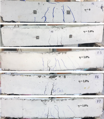
Figure 9. Effect of fibres type on crack pattern of the tested beams
For fiber volume fractions of 1.0%, an analogous cracking pattern is noticeable when comparing the cracking behavior of fiber’s various types. From Figure 9, the top portion of the compression zone, consisting of uncracked concrete, was strengthened by incorporating straight, hooked, and corrugated steel fibers. For SFRC BEAMS with 3 cm and 5 cm hooked SF, one widened crack was observed within the maximum bending region, and it was the first crack. On the other hand, two widened visible cracks developed in the zone between the two applied loads in a corrugated SFRC BEAMS.
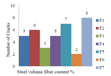
Generally, Table 7 and Figures 8 and 9 demonstrate that beams F2 and F4 show the same number of visible cracks with relatively reduced average spacing than the control beam F1. Less visible cracks also with reduced average spacing were observed for beams F3 and F6. On the other hand, beams F5 and F7 demonstrate the more reasonable crack pattern since more cracks number with relatively small average spacing appeared. This behavior is because an effective transfer of crack surface tensile stress to the surrounding concrete will occur as the SF and reinforcement bars resist these stresses together [21, 34].
(a)
(b)
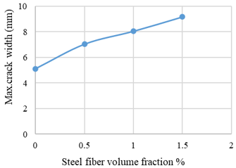
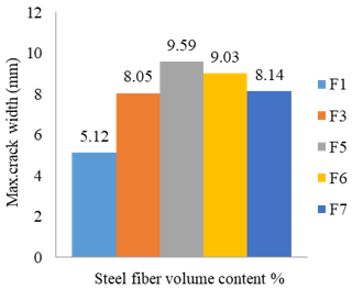
(c)
Figure 10. Cracking behaviour of RC and SFRC beams: (a) effect of SFs content on max. crack width, (b) effect of type of fibers on max. crack width, (c) effect of SFs content and type on number of cracks
Table 7 shows that the maximum crack width increased as the steel fiber content rises. At the same time, at 1.0% fiber volume content, the SFRC beams with 3 cm and 5 cm hooked steel fiber show the larger crack width at the failure stage. These findings could be related to the existence of SF that enables the beams to endure large deformation before failure. Additionally, the above results indicate that increasing the aspect ratio from 50 to 66 effectively reduces the crack width at the same load level. Figure 10 demonstrates the cracking behavior by showing the crack number and largest crack opening recorded in every tested beam.
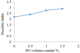
3.2.4 Ductility index
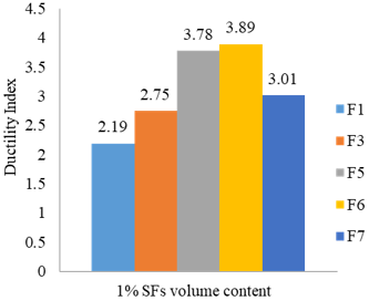
The ductility index (i) of all beams is calculated as i = Δu / Δy, where Δu represent the failure-stage deflection and Δy is the yield-stage deflection [30], measured during the testing process. It's clear from Table 6 that the use of SF causes the beams to undergo additional deformations before failure, which improves the ductility index of all SFRC BEAMS which conforms with the requirements of the ACI provisions [35] and previous studies [13, 17, 19, 30]. Table 7 lists the ductility index of all tested beams. Using 0.5%, 1.0% and 1.5% straight SF enhanced the ductility index of beams F2, F3 and F4 by 10%, 25.6%, and 33%, respectively related to the normal RCB F1. On the other hand, using 1% SF enhanced the ductility of the Corrugated SFRC BEAMS (F7) by 37.4%, and that of 3 cm and 5 cm hooked SFRC BEAMS by 72.6% and 77.6%, respectively. Such results are due to steel fibers' bridging ability, which makes the RCB carry a higher failure load and undergo additional deformations after yielding [32]. Accordingly, the ductility of straight SFRC BEAMS increased with increasing SF's content as shown in Figure 11(a), and for 1% SF, increasing the length of hooked SF to 5 cm slightly enhanced the ductility of the SFRC BEAMS compared to 3 cm hooked SF. On the other hand, the ductility index effectively enhanced with rising aspect ratio as obvious in Table 7 and Figure 11(b). Based on the above result, hooked end (3 cm and 5 cm) and corrugated SFRC BEAMS are favorable for structural members under large deformations, like those in seismic regions, where the ductility should be in the range of 3 to 5 [36, 37]. Figure 11 shows the effect of SF's volume content and types on the ductility of RCB.
(a)
(b)
Figure 11. Ductility of SFRC beams; (a) influence of SFs volume content, (b) influence of SFs type
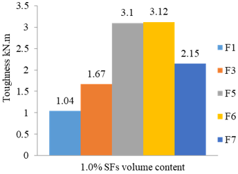
3.2.5 Toughness
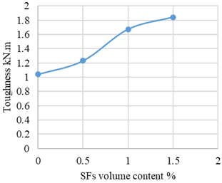
The toughness values for all tested beams are summarized in Table 7. Flexural toughness was determined by calculating the area beneath the load versus midspan deflection curve up to the point of failure [30]. The adoption of SF enhances the toughness results for every tested beam. The toughness increased by 18.3%, 60.6%, and 76.9% for 0.5%, 1.0%, and 1.5% straight SF, respectively, compared to that of RCB as shown in Figure 12(a). Furthermore, using 1.0% hooked (3 cm and 5 cm) and corrugated SF was more effective in enhancing the flexural toughness, which increased by 1.98, 2.0, and 1.07 times, respectively, than the control beam. Also, Table 7 and Figure 12(b) show that the toughness of SFRC beams significantly improved as the aspect ratio increased from 50 to 66. These outcomes are reliable to the findings obtained in the literature [32, 38]. Generally, this behavior is due to the ability of SFRC BEAMS to undergo more deformations, which increases their energy absorption. The notable toughness improvement in hooked SFRC beams, nearly twice that of the control, is likely due to their superior capacity to transfer stress across cracks, which allows higher energy absorption prior to failure. Figure 12 showed the effect of SF on the toughness of RCB.
(a)
(b)
Figure 12. Flexural toughness of SFRC beams; (a) effect of SFs volume content, (b) effect of SFs type
The naked eye recognition and confirmation of slope change in the load-deflection curve were employed to detect the first crack of all tested beams. Table 8 presents the comparison of the experimental and theoretical cracking and ultimate moments. The theoretical moments related to the first flexural crack were determined according to the ACI 318-19 [39] and EC2 [40]. Based on ACI 318-19 [39]:
$M_{cr}^{ACI}=\frac{{{f}_{r}}{{I}_{g}}}{{{y}_{t}}}$ (1)
where, ${{f}_{r}}=0.62\lambda ~\sqrt{f_{c}^{'}}~$is the modulus of rupture; Ig is the centroidal second moment of the gross concrete cross-section; yt is the distance measured from the centroid of the gross concrete cross-section to the tension face; the value of λ depends on the designed equilibrium density, wc, of the concrete mixture or the aggregate composition in the concrete mix used in the design. For lightweight and normal weight concrete λ= 0.75 and 1.0 respectively.
According to EC2 [40]:
$M_{cr}^{EC2}={{f}_{ctm}}\frac{{{I}_{u}}}{\left( h-{{x}_{u}} \right)}$ (2)
where, ${{f}_{ctm}}=0.3~f_{ck}^{0.67}$ is the average value of the concrete axial tensile strength; $f_{ck}^{0.67}$ is the 28 days cylinder compressive strength of concrete; Iu is the un-cracked transformed section inertia moment; xu is the distance measured from N.A. to the compression face, and h is the total depth of the beam.
Table 8 shows that both ACI [39] and EC2 [40] codes underestimated the cracking moment, and the gap between measured and predicted values widened upon incorporating steel fibers. Such behavior is because these two codes do not include the influence of SF when calculating cracking moments.
Table 8. Experimental and theoretical moments
|
Beam No. |
Fiber Volume Content (%) |
Experimental Moment Capacity [kN.m] |
ACI Moment Capacity [kN.m] |
EC2 Moment Capacity [kN.m] |
|||
|
Cracking |
Ultimate |
Cracking |
Ultimate |
Cracking |
Ultimate |
||
|
F1 |
0 |
9.9 |
36.3 |
7.71 |
20.74 |
6.20 |
17.22 |
|
F2 |
0.5 |
11.28 |
38.09 |
8.10 |
20.82 |
6.63 |
18.35 |
|
F3 |
1.0 |
12.24 |
40.29 |
8.65 |
20.92 |
7.24 |
20.53 |
|
F4 |
1.5 |
13.45 |
41.25 |
8.87 |
20.96 |
7.48 |
21.19 |
|
F5 |
1.0 |
15.95 |
40.67 |
8.52 |
20.90 |
7.10 |
19.94 |
|
F6 |
1.0 |
17.88 |
41.25 |
8.38 |
20.88 |
6.94 |
19.47 |
|
F7 |
1.0 |
12.38 |
40.15 |
8.57 |
20.91 |
7.15 |
20.1 |
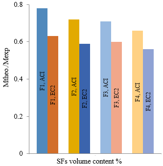
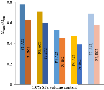
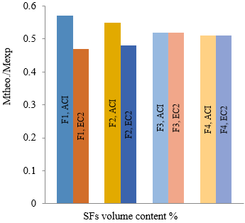
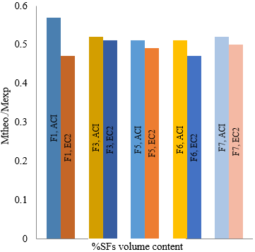
The ultimate experimental and theoretical moments of all tested beams calculated by ACI and EC2 are presented in Table 8. The results showed that ACI and EC2 codes underestimated the ultimate capacity of the tested beams. Since both codes did not include the effect of SF in the equations relating to the ultimate capacity of the RCB, the inclusion of SF enlarges the difference between the experimental and theoretical ultimate moment for both codes. Also, such results can be related to the fact that the philosophy of ACI and EC2 codes state that the nominal capacity of RC members approached when concrete maximum compression strain at the farthest compression fiber reaches 0.003 and 0.0035, respectively. Figures 13 and 14 present the ratios of theoretical to experimental cracking and ultimate moments of the tested beams, respectively.
Figure 13 shows that for cracking moments, the ratio of the ACI theoretical moment to experimental moment is always greater than that of EC2. This difference increases with increasing SF's volume content (Figure 13(a)); at the same time, the 5 cm hooked SF showed the least ratio at 1.0% volume content for both ACI and EC2 codes (Figure 13(b)). Similarly, the ACI theoretical to experimental moment ratio is still greater than the EC2 ratio for the ultimate moment. At the same time, there is no clear trend regarding SF's volume content and type, as shown in Figure 14.
(a) Effect of SFs volume content
(b) Effect of SFs type
Figure 13. Theoretical to experimental ratio of cracking moment
(a) Effect of SFs volume content
(b) Effect of SFs type
Figure 14. Theoretical to experimental ratio of Ultimate moment
In the present work, the SF were adopted to investigate their effect on the conventional concrete characteristics and the behavior of RCB in flexure. For this reason, three different volume content of straight steel fibers (0.5%, 1.0%, and 1.5%) were used together with the control concrete specimen and beam (without SFs). At the same time, 3 cm and 5 cm hooked steel fibers and corrugated steel fibers were used to study the effect of SFs types at 1.0% volume content. Compressive capacity, splitting tensile resistance, and flexural strength were the main parameters which experimentally measured to explore the effect of SF on the normal concrete properties. The cracking and ultimate strength, deflection capacity, ductility, and toughness were also discussed to discover the impact of SF on the behavior of RCB in flexural. Accordingly, the results lead to the following conclusions:
General:
Effect of straight SFs volume fraction:
Effect of SFs types:
For seismic regions, use 1% 5 cm hooked fibers to meet ductility demands of 3-5.
The ACI and EC2 codes underestimated both cracking and ultimate moment of RCB and SFRC BEAMS. The ACI Theoretical to experimental moment ratio was larger than EC2 for both cracking and ultimate moments.
[1] Maccormac, J., Brown, R. (2011). Design of Reinforced Concrete. Ninth Edition, Wiley.
[2] Gu, Z., Wang, J., Gao, D., Zhao, J. (2024). Effects of steel fibers on the flexural behavior of recycled concrete beam: Testing and analysis. Journal of Building Engineering, 85: 108718. https://doi.org/10.1016/j.jobe.2024.108718
[3] Chkheiwer, A.H., Ahmed, M.A., Naser, K.Z. (2021). Modified prediction approach of strength of high strength polyolefin fiber reinforced concrete corbels. Periodicals of Engineering and Natural Sciences (PEN), 9(2): 1141-1151. https://faculty.uobasrah.edu.iq/uploads/publications/1645385568.pdf.
[4] Al-Hussein, A., Majeed, F.H., Naser, K.Z. (2024). Tension lap splices in recycled-aggregate concrete strengthened with steel-polyolefin fibers. Fibers, 12(8): 60. https://doi.org/10.3390/fib12080060
[5] Abed, B.R., Beddu, S., Itam, Z., Khudhair, M.A.A. (2024). Increasing the punching shear capacity of flat plate reinforced concrete utilizing CFRP warp and bar. Mathematical Modelling of Engineering Problems, 11(4): 1013-1020. https://doi.org/10.18280/mmep.110418
[6] Li, Y., Zheng, Z., Zhang, Y., Li, B., Fan, X. (2025). Effect of steel-polypropylene hybrid fiber on the flexural behavior of RC beams under cryogenic freeze-thaw cycles and repeated loading. Engineering Failure Analysis, 170: 109236. https://doi.org/10.1016/j.engfailanal.2024.109236
[7] Rauf, F.L., Whaib, M.S., Elwi, M. (2025). Improving the behavior of damaged reinforced concrete beams. Mathematical Modelling of Engineering Problems, 12(1): 277-283. https://doi.org/10.18280/mmep.120128
[8] Yang, K., Wu, Z., Zheng, K., Shi, J. (2024). Design and flexural behavior of steel fiber-reinforced concrete beams with regular oriented fibers and GFRP bars. Engineering Structures, 309: 118073. https://doi.org/10.1016/j.engstruct.2024.118073
[9] Kassim, M.T.E., Karash, E.T., Sultan, J.N. (2023). A mathematical model for non-linear structural analysis reinforced beams of composite materials. Mathematical Modelling of Engineering Problems, 10(1): 311-333. https://doi.org/10.18280/mmep.100137
[10] Tahenni, T., Bouziadi, F., Kirgiz, M.S., Kouider-Djelloul, O., Boulekbache, B., Amziane, S. (2024). Experimental and numerical study of the effect of stirrups and steel fibres on the shear capacity of reinforced concrete beams. Engineering Structures, 319: 118834. https://doi.org/10.1016/j.engstruct.2024.118834
[11] Yoo, D.Y., Soleimani-Dashtaki, S., Oh, T., Chun, B., Choi, J.S., Banthia, N., Yoon, Y.S. (2024). Effects of amount and geometrical properties of steel fiber on shear behavior of high-strength concrete beams without shear reinforcement. Cement and Concrete Composites, 151: 105606. https://doi.org/10.1016/j.cemconcomp.2024.105606
[12] Zhao, W., Xu, J., Pan, K., Han, X., Wu, Z. (2025). Experimental study on shear behavior of steel fiber high strength concrete beams reinforced with GFRP bars. Engineering Structures, 323: 119294. https://doi.org/10.1016/j.engstruct.2024.119294
[13] Ghalehnovi, M., Karimipour A., Brito, J. (2019). Influence of steel fibres on the flexural performance of reinforced concrete beams with lap-spliced bars. Construction and Building Materials, 229: 116853. https://doi.org/10.1016/j.conbuildmat.2019.116853
[14] Naser, K.Z., Lafta, Y.J., Alhussein, T.H. (2024). Effect of steel fiber type and curing regimen on the mechanical properties of reactive powder concrete. Advances in Civil Engineering, 2024(1): 6616375. https://doi.org/10.1155/2024/6616375
[15] Balaguru, P., Narahari, R., Patel, M. (1992). Flexural toughness of steel fibre reinforced concrete. ACI Materials Journal, 89(6): 541-546. https://doi.org/10.14359/4019
[16] Chiaia, B., Fantilli, A.P., Vallini, P. (2007). Evaluation of minimum reinforced ratio in FRC members and application to tunnel linings. Materials and Structures, 40: 593-604. https://doi.org/10.1617/s11527-006-9166-0
[17] Meda, A., Minelli, F. Plizzari, G.A. (2012). Flexural behaviour of RC beams in fibre reinforced concrete. Composite Part B: Engineering, 43(8): 2930-2937. https://doi.org/10.1016/j.compositesb.2012.06.003
[18] Naaman, A.E., Reinhardt, H.W. (2003). High performance fiber reinforced cement composites HPFRCC-4: International RILEM workshop. Materials and Structures, 36: 710-712. https://doi.org/10.1007/BF02479507
[19] Daniel, J.I., Shah, S.P. (1994). Fibre Reinforced Concrete: Developments And Innovations. American Concrete Institute.
[20] Bindiganavile, V., Banthia, N. (2001). Polymer and steel fibre reinforced cementitious composites under impact loading-Part 1: Bond-slip response. ACI Materials Journal, 98(1): 10-16. https://doi.org/10.14359/10155
[21] Hussain, H.K., Abbas, A.M., Ojaimi, M.F. (2022) Fiber-type influence on the flexural behavior of RC two-way slabs with an opening. Buildings, 12(3): 279. https://doi.org/10.3390/buildings12030279
[22] Abdullah, M.D., Majeed, F.H., Saleh, S.M. (2022). The Role of fiber-type reinforcement in the torsional behavior of solid and hollow reinforced concrete beams. Fibers, 10(9): 80. https://doi.org/10.3390/fib10090080
[23] Altun, F., Haktanir, T., Ari, K. (2007). Effects of steel fiber addition on mechanical properties of concrete and RC beams. Construction and Building Materials, 21(3): 654-661. https://doi.org/10.1016/j.conbuildmat.2005.12.006
[24] Hamoodi, A.Z., Zewair, M.S., Ojaimi, M.F. (2021). Shear behaviour of fiber-reinforced concrete beams: An experimental study, International Journal of GEOMATE, 21(86): 175-187. https://geomatejournal.com/geomate/article/view/44.
[25] Zewair, M.S., Hamoodi, A.Z., Ojaimi, M.F. (2021). Effect of types of fibres on the shear behaviour of deep beam with opening. Periodicals of Engineering and Natural Sciences (PEN), 9(2): 1086-1095. http://doi.org/10.21533/pen.v9i2.1929
[26] Abbas, A.M., Hussain, H.K., Ojaimi, M.F. (2022). Shear and flexural behavior of flat slabs casted with olyolefin Fiber-Reinforced Concrete. Fibers, 10(4): 34. https://doi.org/10.3390/fib10040034
[27] DSS BS EN 12390-3:2019. (2023). Testing hardened concrete- Part 3: Compressive strength of test specimens. https://sbs.sc/wp-content/uploads/2023/03/10.-DSS-SS-BS-EN-12390-3-2019_Redacted.pdf.
[28] ASTM C496/C496M-17. (2017). Standard test method for splitting tensile strength of cylindrical concrete specimens. https://store.astm.org/c0496_c0496m-17.html.
[29] ASTM C78/C78M-22. (2022). Standard test method for flexural strength of concrete (using simple beam with third-point loading). https://store.astm.org/c0078_c0078m-22.html.
[30] Chaboki, R.H., Ghalehnovi, M., Karimipour, A., Brito, J.D. (2018). Experimental study on the flexural behaviour and ductility ratio of steel fibres coarse recycled aggregate concrete beams. Construction and Building Materials, 186: 400-422. https://doi.org/10.1016/j.conbuildmat.2018.07.132
[31] Lim, D.H., Oh, B.H. (1999). Experimental and Theoretical Investigation on the shear of steel fiber reinforced concrete beams. Engineering Structures, 21(10): 937-944. https://doi.org/10.1016/S0141-0296(98)00049-2
[32] Ismail, M.K., Hassan, A.A.A. (2017). An experimental study on flexural behaviour of large-scale concrete beams incorporating crumb rubber and steel fibres, Engineering Structures, 145: 97-108. https://doi.org/10.1016/j.engstruct.2017.05.018
[33] Yoo, D.Y., Yuan, T., Yang, J.M., Yoon, Y.S. (2017). Feasibility of replacing minimum shear reinforcement with steel fibers for sustainable high-strength concrete beams. Engineering Structures, 147: 207-222. https://doi.org/10.1016/j.engstruct.2017.06.004
[34] Aoude, H., Belghiti, M., Cook, W.D., Mitchell D. (2012). Response of steel fiberreinforced concrete beams with and without stirrups. ACI Structural Journal, 109(3): 359-368. https://doi.org/10.14359/51683749
[35] ACI Committee 544. (1988). Design considerations for steel fiber reinforced. Concrete. Structural Journal, 85(5): 563-579. https://doi.org/10.14359/3144
[36] Ashour, S.A. (2000). Effect of compressive strength and tensile reinforcement ratio on flexural behaviour of high-strength concrete beams. Engineering Structures, 22(5): 413-423. https://doi.org/10.1016/S0141-0296(98)00135-7
[37] Gunasekaran, K., Annadurai, R., Kumar, P.S. (2013). Study on reinforced lightweight coconut shell concrete beam behaviour under flexure. Materials and Design, 46: 157-167. https://doi.org/10.1016/j.matdes.2012.09.044
[38] Ning, X., Ding, Y., Zhang, F., Zhang, Y. (2015). Experimental study and prediction model for flexural behaviour of reinforced SCC beam containing steel fibers. Construction and Building Materials, 93: 644-653. https://doi.org/10.1016/j.conbuildmat.2015.06.024
[39] ACI CODE-318-19(22). (2022). Building code requirements for structural concrete and commentary. American Concrete Institute.
[40] EN 1992-1-1. (2004). Eurocode 2: Design of concrete structures. https://www.phd.eng.br/wp-content/uploads/2015/12/en.1992.1.1.2004.pdf.