Samah Ahmed Hardan*![]() | Ehab G. Al-Hasany
| Ehab G. Al-Hasany![]() | Saif K.A. Al-Tameemi
| Saif K.A. Al-Tameemi![]()
© 2025 The authors. This article is published by IIETA and is licensed under the CC BY 4.0 license (http://creativecommons.org/licenses/by/4.0/).
OPEN ACCESS
The existence of openings in slabs is often unavoidable and necessary for architectural reasons. These openings can compromise load-carrying capacity, energy dissipation, stiffness, and ductility of the slab. Therefore, strengthening around the opening is necessary to overcome this deficiency. On the other hand, nowadays glass fiber-reinforced polymer (GFRP) rebars are widely used in concrete slabs as it can provide higher strength, lower weight, greater ductility, and non-corrosive characteristics. However, the behavior and enhancement of GFRP-reinforced concrete slab with opening has not yet been extensively investigated. Therefore, in this work, the effect of opening shape, number, and location were studied. Furthermore, the enhancement of the slab through using additional reinforcement bars and steel plates around the opening was assessed by finite elements simulation. First, the numerical models were validated by comparing their behavior with experimental tests found in the literature. After that, a parametric study was carried out to accomplish the objectives outlined in this paper. The results indicated that the opening shape has no large influence on the current slab while changing the opening location from mid-span to a location near support showed a 19.8% higher load-carrying capacity. When the slab was strengthened by a steel plate all around the opening, an increase of 40% was achieved. Likewise, by attaching CFRP sheets and strengthening with a steel plate on top of the slab, the strength was increased up to 39.2% compared to the slab strengthened with CFRP sheets only.
GFRP reinforcement, slab opening, opening strengthening, steel plate retrofitting, CFRP sheets, finite element simulation
Slabs are important structural elements carrying loads, perpendicular to their planes and directing them to columns and beams as well as horizontal loads, such as those from earthquakes. However, openings in slabs are required for various reasons. These openings are unavoidable and necessary for architecture reasons, elevator shafts, or staircases [1]. The existence of opening in slab will reduce the weight of slab and since the weight of floor can be reduced, the load on beams is diminished. Additionally, the load on support will be eased and the performance under both regular and seismic load conditions will be improved [2]. Nonetheless, the presence of openings affects the behaviour of floor diaphragms and make it unpredictable and more complicated. These openings can compromise load-carrying capacity, stiffness, energy dissipation capacity, and ductility of the slab. Designers consider additional reinforcement for these openings, but the prediction of their location is not easy in design stage due to various reasons such as heating and cooling ducts, air conditioning system placement, placement of electric, or other infrastructure. In other words, the additional reinforcement cannot be performed in the beginning. Therefore, strengthening around the opening is necessary after construction to ensure structure integrity [3]. The externally bonded technique (EBT) using glass fiber-reinforced polymer (CFRP) is approved to be an effective strengthening method because of its easy installation [4-10].
Muhammed [11] carried out experiments on eight self-consolidating concrete slabs with both small and large openings. The results revealed that applying CFRP sheets significantly improved the slabs' load-carrying capacity by 46.67% for slabs with small openings and by 55.7% for those with large openings. Mohamed et al. [5] used ABAQUS software to carry out a numerical study on slabs with openings that were strengthened using CFRP. Their focus was on understanding how the thickness of the CFRP affected the results. The study showed that CFRP laminates greatly enhanced both the flexural capacity and overall stiffness of the slabs with openings. Furthermore, increasing the thickness of the CFRP laminates was found to significantly reduce midspan deflection. In the early 1990s, the use of GFRP rebars instead of steel rebars were investigated by many researchers as GFRP provide corrosion resistance, higher strength as well as its lightweight property [12-16]. Due to the increase of shear lag between fibres, the tensile strength increases as the diameter of the bar increases generally, GFRP bars shows linear stress-strain behaviour up to rupture at the ultimate strength. Moreover, GFRP rebars do not experience strain hardening or yield deformation before reaching ultimate strength [17, 18]. Chang and Seo studied the structural behavior of reinforced concrete slabs with GFRP bars as internal reinforcement, there results indicated that the GFRP-reinforced slabs develop a bilinear elastic response up to the point of failure. With the linear elastic deformation of FRP and the concrete crushing failure mode that comes very often in FRP-reinforced slabs, it has been remarked that GFRP-reinforced slabs are much more flexible after cracking than steel ones. To achieve a deflection-controlled design, higher ratios of reinforcement had to be used. Thereby, this offers sufficient bending stiffness.
Elzaroug et al. [17] experimentally investigated three RC slabs reinforced with GFRP rebars. According to their type of reinforcement. From the test results, it is evident that though the GFRP reinforcement ratio of the test specimens was much higher than the balanced ratio, the slabs performed within the expected limit. The experiments by Attia et al. [19] were conducted on twelve concrete slabs reinforced with one-way BFRP and GFRP bars under a four-point load arrangement. It was observed that all slabs failed due to concrete crushing in the constant moment zone, and no FRP rupture failure was detected as evidenced by measured strain.
Shirmardi and Mohammadizadeh [20] conducted a numerical study to investigate the behavior of 20 concrete beams internally reinforced with GFRP bars. The findings demonstrated that the finite element model successfully simulated the flexural behavior of FRP-reinforced beams. Additionally, the results highlighted that FRP reinforcement is a viable solution for improving the ductility of reinforced concrete beam members.
Golham and Al-Ahmed [21] performed both experimental and numerical investigations to analyze the flexural behavior of one-way concrete slabs with openings, reinforced with GFRP bars and strengthened using CFRP sheets. Their findings revealed that CFRP sheets increased the flexural load-carrying capacity by approximately 52% and 44%, enhanced stiffness at ultimate load by about 101% and 95%, and reduced deflection under service loads by around 56% and 54%, respectively, compared to unstrengthened slabs. The specimens were also modeled using ABAQUS software, and a strong correlation was observed between the experimental and numerical results.
A few studies on a slab reinforced with GFRP bars have been conducted that investigate the effect of opening characteristics, and only a limited range of parameters were considered. In this research, the behavior of GFRP-reinforced concrete slabs with openings was extensively examined. The effect of opening shape, number, and location has been analyzed, and various technic to increase the slab strength were proposed, such as incorporating additional reinforcement bars and steel plates around the opening. These aspects were assessed by using finite element simulations.
2.1 Element type, surface contact, and boundary condition
The FE models were generated in ABAQUS software environment. The concrete was modelled using three-dimensional hexahedral element while shell element was used to model for CFRP sheet and truss element was used for reinforcement. For the contact between the concrete and the CFRP sheets, Tie constraint was assigned while an embedded technique has been used between reinforcement and concrete. Displacement controlled technique has been used to apply the load on the loading plates. To simulate the experimental test pin-roller support condition was assigned in which the transition of one of the supports was restrained against moving in x and y direction while only x direction was restrained in the other one. Figure 1 presents the reference solid slab simulation.
Figure 1. Modeling of the solid reference model (SS-WS)
2.2 Material constitutive models
2.2.1 Concrete
In Abaqus, defining material properties for concrete typically requires inputting both elastic and plastic characteristics. For the elastic behavior of concrete, which describes its response up to the cracking point (around 0.4 $f c^{\prime}$, where $f c^{\prime}$ is the compressive strength), two independent parameters are essential: the elastic modulus (Ec) and Poisson's ratio ($v$). The elastic modulus is often calculated using guidelines like those from the ACI 318 code, with specific values typically summarized in Table 1.
For plastic behavior, the Concrete Damage Plasticity (CDP) model is a commonly used constitutive model designed for finite element analysis. The CDP model is based on plasticity and damage theory, as elaborated by several researchers [22, 23]. Using this model involves defining five key parameters and incorporating uniaxial compressive and tensile stress-strain relationships [24, 25]. These five parameters are biaxial to uniaxial compression ratio ($f_{b o} /f_{c o}$), shape factor (Kc), potential eccentricity ($xi$), dilation angle ($\Psi$), and viscoplastic regularization parameter ($\mu$). Parameters used for the concrete are presented in Table 1.
In addition, the concrete's uniaxial compressive behaviour was modelled utilizing a nonlinear stress-strain model proposed by Saenz [26], and the tensile stress-strain relationship was modelled by the approach presented by Hordijk [27].
Table 1. Plastic and elastic parameters of concrete defined in ABAQUS
|
|
CDP Parameters |
|||||
|
Ec (MPa) |
v |
$\xi$ |
Kc |
fbo⁄fco |
$\mu$ |
$\Psi$ |
|
24870.06 |
0.3 |
0.1 |
0.667 |
1.16 |
0.0001 |
36 |
2.2.2 GFRP and CFRP sheets
GFRP bars exhibit linear behavior up to failure. In this study, GFRP bars were modelled using elastic-perfectly plastic behaver. The CFRP sheets are orthotropic elastic materials. Therefore “LAMINA” material type was used to model the elastic properties of CFRP sheets. The elastic modulus in the hoop direction E1 was found to be 230 GPa which was obtained from the manufacturer. Hashin damage model is used the plastic behavior of the CFRP sheets. The data for modelling GFRP and CFRP can be find in reference [21].
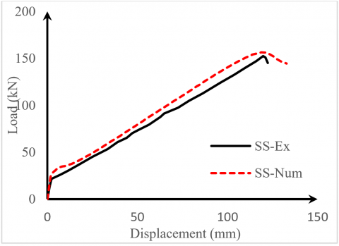
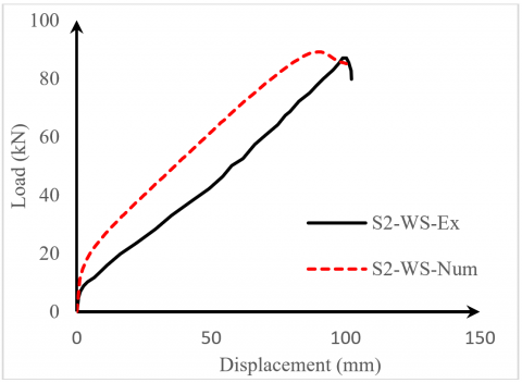
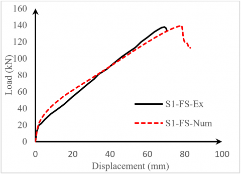
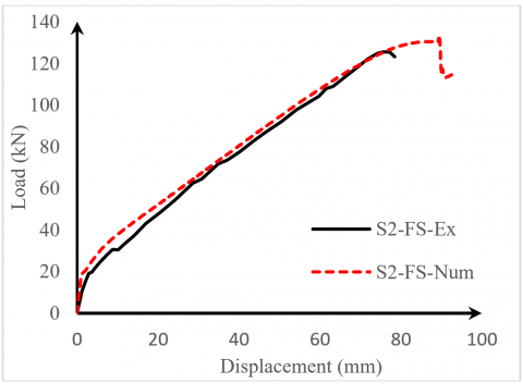
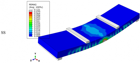
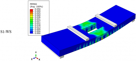
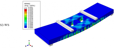
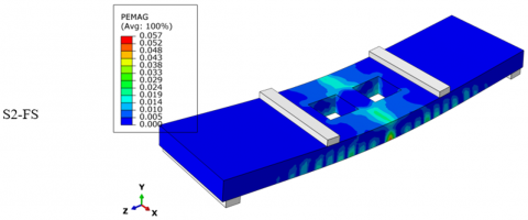
To validate the numerical work, five models were simulated and calibrated against experimental work conducted in reference [21]. The specimens have the designation of SS, S1-WS, S2-WS, S1-FS, and S2-FS. Here, SS represents the solid slab, S1 refers to a slab with one opening, S2 for the slab with two openings, WS denotes the slab without strengthening, and FS refers to the strengthened slab.
Figure 2. Load versus deflection curves for solid slab (SS)
Figure 3. Load versus deflection curves for single opening slab without strengthening (S1-WS)
Figure 4. Load versus deflection curves for two opening slab without strengthening (S2-WS)
Figure 5. Load versus deflection curves for single opening slab strength with CFRP (S1-FS)
Figure 6. Load versus deflection curves for two opening slab strengthened with CFRP sheets (S1-FS)
The results found in reference [21] experimental work conducted were compared with the corresponding value reported in ABAQUS. First, the model's ultimate strengths were cross-checked as shown in Table 2. Second, the load-deflection curves of experimental and numerical work were correlated as presented through Figures 2-6. The Load–deflection curves reveal a good agreement between the experimental and numerical behavior. Furthermore, the ultimate load indicates reliability with a maximum difference of 7%. Finally, the cracks pattern is highlighted in Figure 7.
Table 2. Comparison between the experimental and FEM ultimate strength
|
Specimen Designation |
Pu,exp (kN) |
Pu,FM (kN) |
Pu,exp⁄Pu,FM |
|
SS |
153 |
156 |
0.98 |
|
S1-WS |
90 |
96 |
0.94 |
|
S2-WS |
87 |
90 |
0.98 |
|
S1-FS |
137 |
140 |
0.99 |
|
S2-FS |
125 |
130 |
0.96 |
Figure 7. Crack pattern and failure modes for the calibrated models
To extend the study of the opening effect, several parameters were considered by simulation additional slabs. Different opening shapes so that the one with the lowest impact on slab strength can be recommended. Furthermore, models with various opening numbers and locations were selected whether it was in mid-span or near supports, thus their effect on the slab flexural and shear strength can be evaluated. After that, and when the openings were unavoidable, several strengthening techniques were studied to determine the more efficient method.
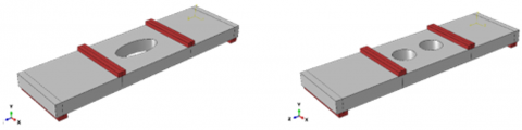
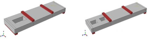
The models were divided into three groups as indicated in Table 3. The first group included four slabs shape and the location of the opening was changed from a rectangular shape previously tested by the reference [21] to the elliptical shape. It includes two slabs where one slab had an elliptical shape opening (S1-WS-E), and the other slab had two openings (S2-WS-E) with elliptical shape as shown in Figure 8. In addition, it includes two slabs where the location of the opening was changed to be near the support (S1-WS-L and S2-WS-L) as shown Figure 9.
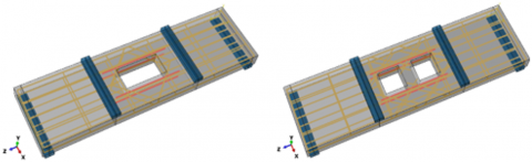
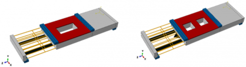
The second group included four models where two slabs were simulated based on Si-WS models, these two was strengthened using rebars around the opening (Si-WS-SB) as showed in Figure 10. and the other model was strengthened using steel plates planted near the opening (Si-WS-SP) as presented in Figure 11.
Third group includes two slabs strengthened with CFRP sheets and steel plates planted at slab top surface. The models were simulated based on S1-FS and S2-FS specimen, the slab strengthened with top steel plates has a designation of S1-FS-SP and S2-FS-SP presented in Figure 12.
Figure 8. Slabs S1-WS-E and S2-WS-E
Figure 9. Slabs S1-WS-L and S2-WS-L
Figure 10. Additional rebars around openings S1-S and S2-S
Figure 11. Slabs S1-SP and S2-SP
Figure 12. Slab S1-SP and S2-SP
Table 3. Slab's designation and its references
|
Group No. |
Model Code |
Opening Shape |
Number of Openings |
Opening Location |
Additional Strengthening Type |
|
Group 1 |
S1-WS-E |
Elliptical |
One |
Centre |
- |
|
S2-WS-E |
Elliptical |
Two |
Centre |
- |
|
|
S1-WS-L |
Square |
One |
Near support |
- |
|
|
S2-WS-L |
Square |
Two |
Near support |
- |
|
|
Group 2 |
S1-SB1 |
Square |
One |
Centre |
Steel bars around opening |
|
S2-SB2 |
Square |
Two |
Centre |
Steel bars around opening |
|
|
S1-SP1 |
Square |
One |
Centre |
Steel plates around opening |
|
|
S2-SP2 |
Square |
Two |
Centre |
Steel plates around opening |
|
|
Group 3 |
S1-FS-SP1 |
Square |
One |
Centre |
Steel plates on top of opening |
|
S2-FS-SP2 |
Square |
Two |
Centre |
Steel plates on top of opening |
5.1 Effect of opening characteristics
5.1.1 Opening shape
It is predicted that round openings will tend to have a less detrimental effect on the slab's stiffness and load-bearing capacity compared to rectangular or irregular shapes. This is because the stress concentration around a circular opening is more evenly distributed, reducing the occurrence of cracking. However, larger circular openings can still significantly reduce the slab's stiffness and capacity. Using the reference models S1-WS and S2-WS simulated based on experimental work stated earlier, to determine the shape effect of the models S1-WS-E1 (one opening) and S2-WS-E1 (two openings) with elliptical opening. No large influence has been recorded by changing the opening shape of the current models as the failure mode was dominated by flexure and mainly depended on tensile bars and concrete compressive block. However, that conclusion is different from that reported by reference [28], their work was focused on steel reinforced concrete slab resistance of punching shear which the opening shape has a large effect on slab strength. The study conducted by reference [29] has a similar conclusion of shape effect, their study was on steel-reinforced concrete slab have an opening with different shapes, the circular opening record similar behavior of rectangular one, when the flexural failure mode is expected.
5.1.2 Opening location
Based on the results obtained from shafting the opening near the slab supports (S1-WS-L and S2-WS-L models), the slab flexural capacity and stiffness were increased. Hence, the opening near support could affect the shear strength nor bending resistance. As stated earlier, the main failure mode was in flexure, thus shifting the opening far from the point of maximum moment doesn’t decrease the slab strength. The same conclusion was observed in references [28, 29]. In the current models, the stiffness for the slab with an opening near support increased by 24.58% in the elastic stage (Kela) and 12.06% after cracking (Kpla) compared to the reference slab while load carrying increased by 19.79% in slab with only one opening compared to reference slab. The results showed that the change of opening’s location of slab with two opening causes less enhancement compared to reference slab.
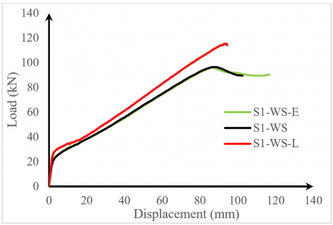
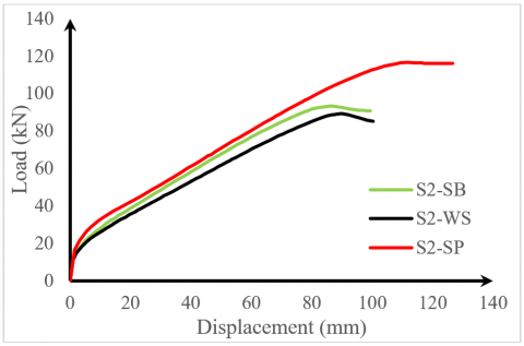
The load-displacement curves, which clarify the behavior of the opening effect either it was the shape influence or its location impact are presented in Figure 13 for slabs with one opening and Figure 14 for the slabs with two openings.
Figure 13. Load-deflection curve of slabs S1-WS-E, S1-WS-L and S1-WS which had one opening
Figure 14. Load-deflection curve of slabs S2-WS-E, S2-WS-L and S2-WS which had two openings
5.2 Effect of add strengthening around the openings
5.2.1 General
Additional reinforcement or steel plates around openings counteract the stress concentration that naturally occurs around the edges of an opening which creates a stronger load path around the discontinuity and prevents the development and propagation of cracks around the opening. Therefore, it is anticipated that the addition of rebars around the opening will affect local Stiffness, and load-bearing capacity can offer better crack control. The impact of these two techniques in slab strengthening can be evaluated based on the behavior presented in the load-deflection curves. The strengthen slab with one opening (S1-SB, S1-SP), and its reference slab without strengthening (S1-WS) are presented in Figure 15, while the load-deflection curves of S2-WS-SB, S2-WS-SP and its corresponding model without strengthening (S2-WS) are highlighted in Figure 16.
Figure 15. Load-deflection curve of slabs S1-WS-SB, S1-SP and S1-SB which had one opening
Figure 16. Load-deflection curve of slabs S2-WS, S2-SB and S2-SP which had two openings
5.2.2 Adding bars around opening
The addition of rebars increased the load-carrying capacity by 4.2%, where this enhancement relies on the additional steel reinforcement area that could minimize the cracks and add to the flexural capacity of the concrete, while no large influence has been recorded for slab stiffness. By splitting the slab opening from one to two with the same area, the additional bar presents more efficiency, which records an enhancement of 5.6%, as the bars are distributed around the opening and control a larger area in the concrete. This conclusion coincides with the ACI code recommendations of providing additional bars near the opening.
5.2.3 Adding steel plates around opening
The addition of plates around the opening shows the best results as the stiffness increased by 16.8% in the elastic stage and 2.8% after cracking compared to the reference model without strengthening. The load-carrying capacity increased up to 40.63% compared to the one-opening slab, as the steel plate can contribute with high efficiency to both the slab's compressive and tensile strength by creating a strong perimeter around the opening. The slab with two openings (S2-SP) recorded less improvement in its ultimate strength, in which the enhancement was 31.1% by comparing it with the slab (S2-WS), the reason for that can be due to presence of the non-strengthened concrete region between the two openings, which expected to fail before the steel plate reach its full potential of strengthening.
5.3 Effect of the planting steel plates at slab top surface
Planting steel plates on top of the opening is predicted to increase the flexural capacity and stiffness. The slab (S1-FS and S2-FS) which have a CFRP sheet strengthening, were modeled as a reference for this group. The reference slabs failed by concrete compressive crushing. Therefore, a planted steel plate was simulated to increase the slab compressive strength in the models S1-FS-SP and S2-FS-SP.
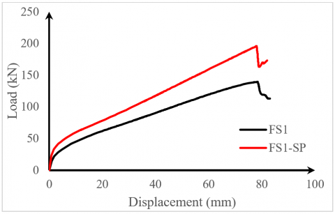
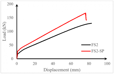
The displacement-load curves extracted from the numerical analysis of these slabs are presented in Figure 17 and Figure 18. Planting the top plate for one opening slab increased the ultimate strength by 39.29% and the stiffness was increased by 72.5% before the occurrence of the crack and increased by 41.09% after cracking. However, the slabs including two openings present less enhancement as the flexural capacity increased by only 26.92%, this can be because high stress was noticed at the opening sides that are closer to the loading point. On the other hand, a similar stiffness was observed to that of the one-opening slab (Table 4).
Figure 17. Load-deflection curve of slabs S1-FS and S1-FS-SP which had one opening
Figure 18. Load-deflection curve of slabs S2-FS and S2-FS-SP which had one opening
Table 4. Results summary
|
Slab Designation |
Kel |
KPl |
Pu (kN) |
$\frac{P_u}{P_{r e f}}$ |
$\frac{K_{e l}}{K_{e l_{r e f}}}$ |
$\frac{K_{p l}}{K_{p l_{r e f}}}$ |
|
S1-WS (reference) |
12 |
1.10 |
96 |
- |
- |
- |
|
S1-WS-E |
12 |
1.10 |
96 |
0.00 |
0.00 |
0.00 |
|
S1-WS-L |
15 |
1.24 |
115 |
19.7 |
24.6 |
12.1 |
|
S2-WS (reference) |
11 |
1.05 |
90 |
- |
- |
- |
|
S2-WS-E |
11 |
1.05 |
90 |
0.0 |
0.0 |
0.0 |
|
S2-WS-L |
11 |
1.09 |
95 |
5.6 |
0 |
4.3 |
|
S1-SB |
12 |
1.27 |
100 |
4.2 |
0.0 |
14.7 |
|
S1-SP |
14 |
1.13 |
135 |
40.6 |
16.8 |
2.8 |
|
S2-SB |
11 |
1.12 |
95 |
5.6 |
0.0 |
6.8 |
|
S2-SP |
11 |
1.07 |
118 |
31.1 |
3 |
2.5 |
|
S1-FS (reference) |
17 |
1.79 |
140 |
- |
- |
- |
|
S1-FS-SP |
29 |
2.53 |
195 |
39.3 |
72.5 |
41.1 |
|
S2-FS (reference) |
18 |
1.60 |
130 |
- |
- |
- |
|
S2-FS-SP |
31 |
2.23 |
165 |
26.9 |
72.8 |
38.9 |
This study investigated the behavior of one-way slabs reinforced with GFRP bars and having an opening. The effect of the opening shape and its location was determined based on the finite element. simulation conducted in this work. Furthermore, several techniques were proposed to enhance this kind of slab. First, the models were validated based on experimental tests reported in the literature. Then, the previously stated parameters were analyzed. The key finding of this study can be summarized as follows:
1) The finite element models developed in this work can capture the behavior of GFRP-reinforced concrete slabs with high accuracy.
2) When the failure modes are dominated by flexure, the effect of the opening shape either it was rectangle or elliptical, has no impact on slab behavior.
3) Shifting the opening away from points of maximum moment increases the stiffness by 24.58% and flexural strength by 12.06%, by assuming it has an adequate shear capacity near supports.
4) Providing steel plates around the openings, has been proven to be the most effective strengthening technique, as it improves the slab strength up to 40.63% in a single-opening slab, and 31.1% in a two-opening slab.
5) The concrete area between the two openings, is identified as the next weak point when this opening is strengthened with steel plates around its perimeter. This region could be further strengthened in future studies.
6) By planting a steel plate in the concrete compressive region, the improvement percentage in the slab's ultimate strength reached 39.29% for one opening slab and 26.9% for the two opening slabs. Which these slabs were already strengthened with CFRP sheets in its bottom fiber.
Based on the findings and limitations of this research, the following points are recommended to investigation further for future studies:
(1) Use high-strength concrete to clarify its impact on the model's compressive strength and its ultimate capacity.
(2) Clarify the influence of the same parameters used in this study when the failure mode is dominated by shear.
(3) Enhance the strength of the concrete region between the two openings in the slabs that have a steel plate around its opening.
(4) Use different strength techniques to investigate its impact such as near-surface mounted (NSM), and BFRP sheets.
[1] Chang, K., Seo, D. (2012). Behavior of one-way concrete slabs reinforced with GFRP bars. Journal of Asian Architecture and Building Engineering, 11(2): 351-358. https://doi.org/10.3130/jaabe.11.351
[2] Hua, L.J., Tang, H.S., Leong, W.K., Sia, H.T. (2020). Behaviour of reinforced concrete beams with circular transverse openings under static loads. Journal of Science and Applied Engineering, 3(1): 1-16. https://doi.org/10.31328/JSAE.V3I1.1288
[3] Kaya, N., Anil, Ö. (2021). Prediction of load capacity of one way reinforced concrete slabs with openings using nonlinear finite element analysis. Journal of Building Engineering, 44: 102945. https://doi.org/10.1016/J.JOBE.2021.102945
[4] Salman, W.D. (2024). Strengthening of reinforced concrete one-way slabs with opening using CFRP strip in flexural. International Journal of Science and Research, 4: 2319-7064. https://www.researchgate.net/publication/282505528.
[5] Mohamed, O., Khattab, R., Okasha, N. (2019). Numerical analysis of RC slab with opening strengthened with CFRP laminates. IOP Conference Series: Materials Science and Engineering, 603(4): 042038. https://doi.org/10.1088/1757-899X/603/4/042038
[6] Casadei, P., Ibell, T., Nanni, A. (2003). Experimental results of one-way slabs with openings strengthened with CFRP laminates. In Fibre-Reinforced Polymer Reinforcement for Concrete Structures, pp. 1097-1106. https://doi.org/10.1142/9789812704863_0105
[7] Anil, Ö., Kaya, N., Arslan, O. (2013). Strengthening of one way RC slab with opening using CFRP strips. Construction and Building Materials, 48: 883-893. https://doi.org/10.1016/J.CONBUILDMAT.2013.07.093
[8] Shehab, H.K., Eisa, A.S., El-Awady, K.A. (2017). Strengthening of cutouts in existing one-way spanning RC flat slabs using CFRP sheets. International Journal of Concrete Structures and Materials, 11: 327-341. https://doi.org/10.1007/S40069-017-0186-7/FIGURES/22
[9] Enochsson, O., Lundqvist, J., Täljsten, B., Rusinowski, P., Olofsson, T. (2007). CFRP strengthened openings in two-way concrete slabs–An experimental and numerical study. Construction and Building Materials, 21(4): 810-826. https://doi.org/10.1016/J.CONBUILDMAT.2006.06.009
[10] Aman, S.S., Mohammed, B.S., Wahab, M.A., Anwar, A. (2020). Performance of reinforced concrete slab with opening strengthened using CFRP. Fibers, 8(4): 25. https://doi.org/10.3390/FIB8040025
[11] Muhammed, N.J. (2012). Experimental study of self compacting RC slabs with opening strengthening with carbon fiber laminated and steel fiber. Journal of Engineering and Sustainable Development, 16(1): 54-74.
[12] Benmokrane, B., Chaallal, O., Masmoudi, R. (1995). Glass fibre reinforced plastic (GFRP) rebars for concrete structures. Construction and Building Materials, 9(6): 353-364. https://doi.org/10.1016/0950-0618(95)00048-8
[13] Alsayed, S.H., Al-Salloum, Y.A., Almusallam, T.H. (2000). Performance of glass fiber reinforced plastic bars as a reinforcing material for concrete structures. Composites Part B: Engineering, 31(6-7): 555-567. https://doi.org/10.1016/S1359-8368(99)00049-9
[14] Michaluk, C.R., Rizkalla, S.H., Tadros, G., Benmokrane, B. (1998). Flexural behavior of one-way concrete slabs reinforced by fiber reinforced plastic reinforcements. ACI Structural Journal, 95: 353-365.
[15] Hassan, T., Abdelrahman, A., Tadros, G., Rizkalla, S. (2000). Fibre reinforced polymer reinforcing bars for bridge decks. Canadian Journal of Civil Engineering, 27(5): 839-849. https://doi.org/10.1139/L99-098
[16] El-Salakawy, E., Benmokrane, B. (2004). Serviceability of concrete bridge deck slabs reinforced with fiber-reinforced polymer composite bars. Structural Journal, 101(5): 727-736. https://doi.org/10.14359/13395
[17] Elzaroug, O., Forth, J., Ye, J., Beeby, A. (2013). Flexural performance of concrete slabs reinforced with GFRP rebars. In Civil and Environmental Research, Special Issue for International Congress on Materials & Structural Stability, Rabat, Morocco, pp. 6-11.
[18] Tharmarajah, G., Taylor, S., Robinson, D. (2023). Experimental and numerical investigation of compressive membrane action in GFRP-reinforced concrete slabs. Polymers, 15(5): 1230. https://doi.org/10.3390/POLYM15051230
[19] Attia, K., Alnahhal, W., Elrefai, A., Rihan, Y. (2019). Flexural behavior of basalt fiber-reinforced concrete slab strips reinforced with BFRP and GFRP bars. Composite Structures, 211: 1-12. https://doi.org/10.1016/J.COMPSTRUCT.2018.12.016
[20] Shirmardi, M.M., Mohammadizadeh, M.R. (2019). Numerical study on the flexural behaviour of concrete beams reinforced by GFRP bars. Journal of Rehabilitation in Civil Engineering, 7(4): 88-99. https://doi.org/10.22075/JRCE.2018.14701.1268
[21] Golham, M.A., Al-Ahmed, A.H.A. (2023). Behavior of GFRP reinforced concrete slabs with openings strengthened by CFRP strips. Results in Engineering, 18: 101033. https://doi.org/10.1016/j.rineng.2023.101033
[22] Lubliner, J., Oliver, J., Oller, S., Onate, E. (1989). A plastic-damage model for concrete. International Journal of Solids and Structures, 25(3): 299-326. https://doi.org/10.1016/0020-7683(89)90050-4
[23] Lee, J., Fenves, G.L. (1998). Plastic-damage model for cyclic loading of concrete structures. Journal of Engineering Mechanics, 124(8): 892-900. https://doi.org/10.1061/(ASCE)0733-9399(1998)124:8(892)
[24] Reuter, U., Sultan, A., Reischl, D.S. (2018). A comparative study of machine learning approaches for modeling concrete failure surfaces. Advances in Engineering Software, 116: 67-79. https://doi.org/10.1016/J.ADVENGSOFT.2017.11.006
[25] Chen, W.F., Han, D.J., Han, D.J. (2007). Plasticity for Structural Engineers. J. Ross Publishing.
[26] Saenz, L.P. (1964). Discussion of equation for stress-strain curve of concrete by Desai and Krishnan. ACI, 61(9): 1229-1235.
[27] Hordijk, D.A. (1992). Tensile and tensile fatigue behaviour of concrete; experiments, modelling and analyses. Heron, 37(1).
[28] Yooprasertchai, E., Tiawilai, Y., Wittayawanitchai, T., Angsumalee, J., Joyklad, P., Hussain, Q. (2021). Effect of shape, number, and location of openings on punching shear capacity of flat slabs. Buildings, 11(10): 484. https://doi.org/10.3390/buildings11100484
[29] Ibrahim, K.A., Al-Darzi, S.Y., Shukur, M.H. (2023). Effect of openings on simply supported reinforced concrete skew slabs using finite element method. Open Engineering, 13(1): 20220464.