Moussa Charif*![]() | Mourad Allad
| Mourad Allad![]() | Mohand Otahar Bensidhoum
| Mohand Otahar Bensidhoum![]()
© 2024 The authors. This article is published by IIETA and is licensed under the CC BY 4.0 license (http://creativecommons.org/licenses/by/4.0/).
OPEN ACCESS
This paper presents simplest fuzzy logic controller (SFLC) PLC’s based implementation applied to the cascade control strategy. Level and flow control loops are important and widely used in the oil and manufacturing industries to ensure a quality product. The control is used to maintain the level of the liquid in the tank at the desired value by manipulating the liquid in the reservoir. Two fuzzy sets on each input variable, five fuzzy sets on the output variable, five linear control rules, algebraic product bounded AND/OR operator, Larsen product inference and Centre of Sums (CoS) defuzzification are the components of this simplest nonlinear fuzzy controller to be implemented. The proposed work deals with the real implementation of a simplest fuzzy logic cascade control strategy designed on SIMATIC S7-300 Plc based on ladder diagram (LD) programming. In this paper, we have presented the results of the experimental tests of the conventional PI control strategy as well as the simplest fuzzy PI implementation applied to a PUL-2/EV cascade control device. Experimental results using this simplest fuzzy PI controller with the setpoint error shown that the setpoint tracking rise time can be reduced by 30% and the disturbance rejection time is decreased at 7sec compared to the conventional PID-PLC based controller, and concluded by stressing the importance of this new controller implementation.
programmable logic controller, PLC, conventional controller, PID, simplest fuzzy controller, SFLC, level/ flow cascade control
A very effective and reliable device is the programmable logic controller (PLC). It is interesting for applications in the industrial automation systems. The ISO/IEC61131 (2001) standard defines programming languages for PLC; such as the LD is the standard programming language, which is greatly used by PLCs programmers. Furthermore, the availability of programmable controllers with floating-point mathematical functions, new approaches to the implementation of complex, advanced control algorithms have been created using advanced functional instructions and improved graphical user interfaces (GUIs) for programming these controllers [1, 2]. Currently, the industrial PLC can receive and send out several analogs and digital inputs/outputs. In other words, the programmable controller can trait simultaneously various programs in order to realize a complex control procedure [3]. This modern performance of PLCs has enabled much research into implementing new, more complex control algorithms for industrial applications.
An interesting work using the LabJack U3 acquisition card and a platform MATLAB Guide. In this study, a various control techniques are applied to the Level/Flow control unit PUL-2/EV [4]. Furthermore, they shown different combinations of three controllers in order to realize the cascade control strategy. After that, they have demonstrated the benefits of combinations. The conventional PID controller integrated inside the programmable logic controllers are not well suited for complex nonlinear and time delayed systems. For those systems, fuzzy logic based controllers have a good control strategy that provides better dynamic performance.
In the specialized literature, many works present the mathematical modelling of the simplified fuzzy controller which involve a reduced number of inputs and outputs signals using the approach based on the approximation of membership functions which are chosen as singletons on the interval [X, Y] of the controlled application [5]. An interesting study on one- and two-dimensional fuzzy controller mathematical models and properties are proposed [6]. A new mathematical approach to simplified fuzzy PI/PD controllers using identical discourse universe for the two scaling inputs [7]. In the work cited above, L-type, П-type and Γ-type membership functions are used for the displayed scaled output variable. The output control signal is calculated applying Larsen product inference with three linear fuzzy control rules.
A small gain theorem under sufficient closed loop control stability conditions for bounded input and bounded output (BIBO) to synthesize a fuzzy PI controller [8]. Analytical structure of the simplest Mamdani type fuzzy PI or PD for two-input, two-output (TITO) controller was developed using Mamdani minimal inference method [9]. Very interesting calculus approach for mathematical models of the simplest fuzzy controllers applied for single-input single-output (SISO) is presented in the study [10]. This new approach extends to the TITO case [11]. In addition, a good analytical modeling of the simplest nonlinear fuzzy two input and two output PI-PD controllers for both Mamdani minimum Inference and height defuzzification [12, 13]. These works present interesting mathematical models of fuzzy controllers, providing information on how a fuzzy controller works and allowing its implementation in an industrial PLC.
Moreover, the implementation of fuzzy controller in Siemens S7-300 PLC has been denoted in the study [14]. Nikolić et al. [15] used the automaton as an integrated element of a SCADA system, where the fuzzy controller program is not implemented directly in the programmable controller but as a subprogram application of the SCADA systems. A version of the fuzzy controller is implemented using the Siemens S7-300 controller, programmed under ladder logic language applied to a wastewater system [16]. This technical paper deals with the implementation of simplest fuzzy PI-PD controller using Siemens S7-300 PLC with analog I/O unit. The real implementation of this controller uses two analog inputs for data acquisition and two analog outputs to control the actuators, triangular membership functions and a rule base of 81 cells, each cell denoted by a pair of numbers (p, q), where p and q come from the scaled input plane partitioning.
After the introduction, this document is structured as follows: The second part describes mathematically and structurally the proposed simplified nonlinear fuzzy controller TITO PI-PD. Then, a description of the experimental level/flow control unit, its various components and their mathematical identification model is given in Section 3. The implementation of the simplest non-linear fuzzy PI controller under Siemens S7-300 PLC and the Cascade Control strategy are briefly presented in Sections 4 and 5. Section 6 presents and discusses simulation tests and experimental results. Conclusions are given in the final Section 7.
The control based on Fuzzy strategies was first proposed by Lotfi A. Zadeh in 1965. Since then, fuzzy logic has emerged as a powerful technique for complex industrial process control due to non linearities or time-varying responses, where it is difficult to model their dynamic behavior. Conventional PID controllers do not work well for these systems.
In such cases, fuzzy controllers, which are intrinsically non-linear, offer better performance. However, the traditional fuzzy controller uses many fuzzy sets for the input and output blocks, which increases the time taken to calculate the control value and limits their implementation on an industrial PLC. The simplest fuzzy controller, on the other hand, is one that uses a minimum number of fuzzy sets for the input and the output. The input-output relations of linear discrete-time tow input and tow output PI controller in speed form which are given by the study [11]:
$\Delta {{u}_{1}}(q)={{K}_{{{P}_{1}}}}\Delta {{e}_{1}}(q)+{{K}_{{{I}_{1}}}}\Delta {{e}_{1}}(q)+{{s}_{21}}\left[ {{K}_{{{P}_{2}}}}\Delta {{e}_{2}}(q)+{{K}_{{{I}_{2}}}}\Delta {{e}_{2}}(q) \right]{{u}_{1}}(q)={{u}_{1}}(q-1)+\Delta {{u}_{1}}(q)$ (1)
$\Delta {{u}_{2}}(q)={{s}_{12}}\left[ {{K}_{{{P}_{1}}}}\Delta {{e}_{1}}(q)+{{K}_{{{I}_{1}}}}{{e}_{1}}(q) \right]+{{K}_{{{P}_{2}}}}\Delta {{e}_{2}}(q)+{{K}_{{{I}_{2}}}}{{e}_{2}}(q){{u}_{2}}(q)={{u}_{2}}(q-1)+\Delta {{u}_{2}}(q)$ (2)
Equivalently, the linear discrete-time of proportional derivative controller in position form formulas are given by:
${{u}_{1}}(q)={{K}_{{{P}_{1}}}}{{e}_{1}}(q)+{{K}_{{{D}_{1}}}}\Delta {{e}_{1}}(q)+{{s}_{21}}\left[ {{K}_{{{P}_{2}}}}{{e}_{2}}(q)+{{K}_{{{D}_{2}}}}\Delta {{e}_{2}}(q) \right]$ (3)
${{u}_{2}}(q)={{s}_{12}}\left[ {{K}_{{{P}_{1}}}}{{e}_{1}}(q)+{{K}_{{{D}_{1}}}}\Delta {{e}_{1}}(q) \right]+{{K}_{{{P}_{2}}}}{{e}_{2}}(q)+{{K}_{{{D}_{2}}}}\Delta {{e}_{2}}(q)$ (4)
where,
$\begin{matrix} {{e}_{1}}(q)={{r}_{1}}(q)-{{y}_{1}}(q) \\ \Delta {{e}_{1}}(q)={{e}_{1}}(q)-{{e}_{1}}(q-1) \\\end{matrix}$ (5)
$\begin{matrix} {{e}_{2}}(q)={{r}_{2}}(q)-{{y}_{2}}(q) \\ \Delta {{e}_{2}}(q)={{e}_{2}}(q)-{{e}_{2}}(q-1) \\\end{matrix}$ (6)
with
$K_{P_1}$ and $K_{P_2}$ are proportional factors;
$K_{I_1}$ and $K_{I_2}$ are integral factors;
r1and r2are reference commands;
y1and y2are outputs of TITO process;
u1and u2are outputs of TITO controller;
s12and s21(- or +) signs depend on the loops interactions.
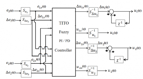
Figure 1 indicates the typical block diagram of the TITO fuzzy PI-PD controller with:
Se1, SΔe1, Se2, and SΔe2 are input scaling factors;
$S_{\Delta u_1}^{-1}$ and $S_{\Delta u_2}^{-1}$ are output scaling factors for PI;
$S_{\Delta u_1}^{-1}$ and $S_{\Delta u_2}^{-1}$ are output scaling factors for PD;
e1s(q), Δe1s(q), e2s(q), and Δe2s are scaled input;
Δu1s(q) and Δu2s(q) are scaled outputs for PI;
u1s(q) and u2s(q) are scaled outputs for PD.
It must be noted that the interaction between the two loops determines the signs of S12 and S21. Proposed in the study [17] and finalised in the study [11], the type of input-output relationships of the simplest nonlinear fuzzy PI/PD controller is based on L-type and Γ-type member ship function to calculate the scaled input variables in the fuzzification part. The control contains five rules, obtained via Larsen product.
Figure 1. TITO fuzzy controller block diagram
The fuzzification part of this controller use L-type and Γ-type membership functions, as scaled input variables and the membership functions for the scaled outputs Δujs(q) for j=1, 2 are shown in Figure 2.
Figure 2. Input and output membership function
The control rule base consists of five rules in the following form:
$\begin{matrix} f{{e}_{1s}}(q)=E_{1}^{_{{{I}_{1}}}}\text{and }\Delta {{e}_{s1}}(q)=\Delta E_{1}^{{{I}_{2}}}\text{ and } \\ {{e}_{2s}}(q)=E_{1}^{_{I3}}\Delta {{e}_{s2}}(q)=\Delta E_{1}^{{{I}_{4}}} \\\end{matrix}\\\text{then }{{\Delta }_{{{u}_{1s}}}}(q)=\Delta U_{1}^{{{J}_{1}}}\text{ and }{{\Delta }_{{{u}_{2s}}}}(q)=\Delta U_{2}^{{{J}_{2}}}$ (7)
where I1, I2, I3 and I4 are the indices of the input fuzzy sets with values -1 or +1, J1and J2 are the indices of the output fuzzy sets having value (-2, -1, 0, +1 or +2) with membership functionsµ µΔUjJn for j, n=1 and 2. The inference engine uses the membership functions of the modified fuzzy sets ΔŨj-2, ΔŨj-1, ΔŨj0, ΔŨj+1 and ΔŨj+2, obtained using Larsen product, which are represented by the hatched areas in Figure 3.
Figure 3. Modified output membership function
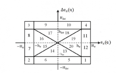
The region of scaled input plan detailed in the study [11] and given in Figure 4 shows the top view of the three-dimension plot with the axes es(q), ∆es(q) and µ. In this scaled input plan, all combinations of input variables are represented. The appropriate control law in each region of the scaled input plan is shown in Figure 3.
The calculation of the scaled output value in the defuzzification part uses the CoS method based on the study [18]. This scaled output value is given by:
\[\Delta u_{js}^{*}(q)=\frac{\sum\nolimits_{l=1}^{5}{A({{\mu }_{Rl}})C({{\mu }_{Rl}})}}{\sum\nolimits_{l=1}^{5}{A({{\mu }_{Rl}})}}\]
where, A(µRl) and C(µRl) are the area and centroid, respectively, of the lth lth derived output membership function of the jthoutput.
Figure 4. Scaled input plan
This section includes short description of our PUL-2/EV practical’s application which is based around a Level/Flow laboratory unit. The Level/Flow control unit application consists of a pumping subsystem equips with DC motor pump, manual valves (2), solenoid and electrical proportional control valve respectively (3, 1) and analogue sensors used for level/flow measuring transmitters (4, 5) as show in Figure 5.
Figure 5. Experimental test unit
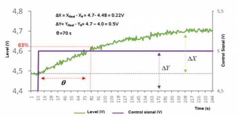
The controller operates the proportional level valve. The valve is closed at zero control voltage and fully open at 10 V. The valve opening is proportional to the control voltage applied. The level and flow vary between 0 to 500 mm and 0 to 5 l/min respectively. The level and flow vary between 0 to 500 mm and 0 to 5 l/min respectively. The measuring signals are adjusted to vary between 0 and 10 V. A bounded deterministic disturbance step is generated by the solenoid valve (3). The identified model is never perfect due to various factors such as component reliability and measurement noise, so the choice of identification method is important. A first order system response was used to model the step response shown in Figure 6.
According to the level step response, we can identify that:
Static GAN
$K=\frac{\Delta X}{\Delta Y}=\frac{4.7-4.48}{4.5-4.0}=0.44$ (9)
Constant time: $\theta \approx 70s$.
The transfer function can be expressed by:
${{G}_{L}}\left( p \right)=\frac{{{K}_{L}}}{1+{{\theta }_{L}}p}=\frac{0.44}{1+70p}$ (10)
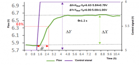
And according to the flow step response, the transfer function can be expressed by:
${{G}_{F}}\left( p \right)=\frac{{{K}_{F}}}{1+{{\theta }_{F}}p}=\frac{0.79}{1+1.2p}$ (11)
Figure 6. Level and flow step response
In this study, the PLC installed for control system is a highly modular Siemens S7-300 PLC (shown in Figure 3) programmed to monitor, control and analyse the sequential mode for safety operating. The implementation of the fuzzy system described in section 2 is by the using of STEP 7 ladder programming.
This PLC is fitted with 24V, 2A power supply, 314-2DP CPU module, an MPI/DP communication processor used to load the program in the programming station into PLC and HMI panel, 24 digital input channel, 16 digital output channel, analog I/O module which allows us to use 5 analog Input channel and 2 Output analog ones, 12-bit ADC and DAC converters with ±10V maximum input/output range. As input variables of the fuzzy block program, two bipolar voltages are considered on the PIW752 and the PIW752. The resulting outputs voltage is applied on analog Output module part at the address PQW752 and PQW754. In the main program, a simplified method of the fuzzy controller is developed, where at each acquisition cycle, the voltages are adapted by applying scaling gains, and then determine their membership degree to corresponding fuzzy sets. At the end, after the application of inference and defuzzification block, the output voltage is determined and transferred to the analog outputs addressed more exactly at PQW752, PQW754. The HMI virtual sliders are used as set-point variables. The level and flow responses measured respectively by level and flow sensors are set to the controller using two lanes of PLC’s analog input module. As detailed in Arnu and Mohan (2016), the mathematical relations between the inputs and outputs of the fuzzy logic regulator are obtained by means of the algebraic product as AND operator, bound sum for OR, feedback product for the inference and the CoS method for defuzzification according the study [5], the crisp value of the scaled output is expressed by the Eq. (8) previously presented.
The expression of the surfaces and centers of the inferred belonging functions of the outputs are:
$\begin{gathered}A\left(\mu_{-2}\right)=0.5\left(A_j+B_j\right) \mu_{-2} ; A\left(\mu_{+2}\right)=0.5\left(A_j+B_j\right) \mu_{+2} \\ A\left(\mu_{-1}\right)=\left(A_j+B_j\right) \mu_{-1} ; A\left(\mu_{+1}\right)=\left(A_j+B_j\right) \mu_{+1} \\ A\left(\mu_0\right)=\left(A_j+B_j\right) \mu_0\end{gathered}$
and
$\begin{gathered}C\left(\mu_{-2}\right)=\frac{-5\left(A_j+B_j\right)^2-A_j B_j}{3\left(A_j+B_j\right)} ; C\left(\mu_{+2}\right)=\frac{5\left(A_j+B_j\right)^2+A_j B_j}{3\left(A_j+B_j\right)} \\ C\left(\mu_{-1}\right)=-\left(A_j+B_j\right) ; C\left(\mu_{+1}\right)=\left(A_j+B_j\right) ; C\left(\mu_0\right)=0\end{gathered}$
with Aj, Bj are the linguistic outputs values of the modified output membership function shown in Figure 3.
The S7-SCL (Structured Control List) language is used to ensure a degree of flexibility in the implementation program. FB and FC blocks are programmed to perform the various calculations required. The first step in the controller implementation process is to calculate its input variables, consisting of four inputs: the first error e1, the derivative of this error ∆e1, the second error e2 and the derivative of this error ∆e2, which are programmed in block FB20. Depending on the value of each error and its derivative, the corresponding cell can take on an integer value between 1 and 9 based on the subspaces shown previously in Figure 4.
The assembly of the previously determined cells is programmed in function block FC22. This block merges the result of the two cells found from block FC21 to give an integer expressing the global cell ranging from 11 to 99. The FC23 block calculates the controller outputs, which are the control variations as a function of the global cell.
The numeric value of the output will be transformed to integer value (0-27648) using an unscale function block FC106 and loaded into the PQW752/ PQW754 output address device. The biggest advantage of this technique is its simplicity of implementation in a PLC’s environment.
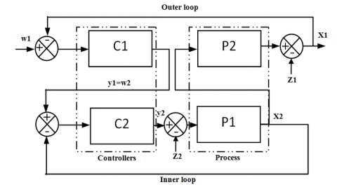
The combination of two controllers is known as cascade control. where the master controller output signal is the set point of the slave controller generally using for processes that have a long response time as presented in Figure 7.
A single feedback controller forms both the inner and outer control loops. The controller in the outer loop is the master controller (C1), and the inner loop controller is slave controller (C2). The main advantage of cascade control is that any disturbance is rejected by the slave controller before it occurs on the master controlled output.
Figure 7. Cascade control block diagram
In this control strategy using the simplified fuzzy controller which is made up of two distinct blocks, the liquid level represents the variable of the external loop to be controlled by the first block of the proposed fuzzy compensator, and the flow rate that of the fast dynamic internal loop controlled by the second block of the controller where its set point represents the output signal of the first controller in order to reject any disturbance before it reaches the main controlled output.
Despite the wealth of sophisticated tools, including advanced controllers, the PID controller is still the most widely used in modern industrial processes [19]. Several works have described the PID structure, such as series or interacting form, standard or non-interacting form and parallel form. Various methods (Ziegler and Nichols, Broida, etc.) were applied for determining PID parameters for parallel PI controllers, the control signal is given by:
$Y\left( t \right)={{G}_{r}}\varepsilon \left( t \right)+\frac{1}{{{T}_{i}}}\int\limits_{0}^{t}{\varepsilon \left( t \right)dt}$ (12)
By imposing the closed loop transfer function (reference model):
$F\left( P \right)=\frac{C(p)G(p)}{1+C(p)G(p)}=\frac{1}{1+{{\theta }_{d}}p}$
The transfer function of controller is:
$C\left( p \right)=\frac{1}{{{\theta }_{d}}pG\left( p \right)}\to C\left( p \right)=\frac{1+\theta p}{K{{\theta }_{d}}p}$ (13)
Parallel PI controller:
$C(p)={{G}_{r}}+\frac{1}{{{T}_{i}}p}$ (14)
By similitude of (4) and (5), the parameters of PI are:
${{G}_{r}}=\frac{1}{K}\frac{\theta }{{{\theta }_{d}}}\text{ and }{{T}_{i}}=K.{{\theta }_{d}}$ (15)
The proposed method gives for the level and flow controller parameters respectively: $G_r=10, T_i=70 \mathrm{~s}$ and $G_r=0.57, T_i=1.2 \mathrm{~s}$.
The analogue output module used has a physical saturation of the output voltages between 0 and 10 V, so all the control signals are adapted to this saturation.
This section presents PLC-based experimental results for the simplest classical PID controller and non-linear fuzzy PI controller. The experiments were done on an experimental Level/Flow control unit level for several level set-point and disturbance rejection. The total programme memory required for this simplest fuzzy controller implementation on the PLC, by choosing the design described above is 312 Bytes. The execution time of the algorithm developed is between 14 and 21 ms, achievable through the use of the OB35 timer interrupts or other dedicated PLC resources. The experimental results are as shown in Figure 8.
Figure 8. PID- PLC based cascade control tracking response
First experiment which has been done on the control system was oriented to test the PID mode controller, note that the static error is zero, rise time (Tr) of 16 seconds and disturbance rejection time is 9 seconds with a small overshoot during the tracking test, this overshoot being the result of the constraints imposed on the speed of the dynamic response.
Figure 9. Simulation results
The simplest fuzzy PI controller algorithm developed was originally implemented in MATLAB/Simulink where the simulation results are shown in Figure 9. The simulation results obtained shows that the mathematical model of the simplest nonlinear fuzzy PI controller model provides stability, steady state error is zero, rise time of 11 seconds with a small overshoot during the tracking test.
The central unit of our PLC begins by analysing the main programming block, called organisation block 1 (OB1), in which all the sub-programs used to process inputs/outputs, data conversions and normalisations are programmed in LD.
The control algorithms developed are programmed in 3 different Function Blocks. Firstly, the FB30 contain the fuzzy program controllers. Secondly, the function block FB20 is used for input calculation. Third, the FB21 has the role of controlling calculations using the instance data block (DB30, DB20, DB21). These blocks associated four Function (FC) where FC20 is used for input normalization, and FC21 and FC22 for cell calculation and assembly. The calculation of output signal control is realized by the FC23 block. The measurement input and output signals are normalized by Scale/Unscale preprogrammed function respectively FC105 and FC106. Finally, both the SCL and LAD are used for programming the control algorithm. The structure of the controller is shown in Figure 10.
Figure 10. PLC’s program structure for simplest nonlinear fuzzy PI controller
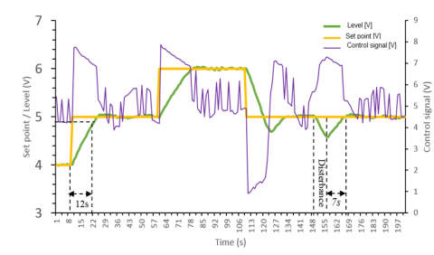
In the experimental tests we applied several set-point tracking. The results show that the simplest non-linear fuzzy PI controller we have implemented provides a good margin of stability, the steady-state error is zero, the rise time is 12 seconds and the disturbance rejection time is 7 seconds without overshoot during the tracking test which validates our implementation approach. However, the hysteresis effect of the proportional valve on the control is more apparent in this mode.
According to Figure 11 control signal have oscillation because the control law has different cells. In other words, the value is calculated based on the position of different input signals for each cell includes inside the called scaled input plan presented in Figure 4. The program memory capacity required to implement this simplest non-linear fuzzy controller on the PLC is 33206 bytes.
Figure 11. Simplest nonlinear fuzzy PI experimental results
The supervisory control and data acquisition (SCADA) system of process developed (for real-time monitoring and control) using the SIMATIC HMI panel is composed of several windows. The HMI process window shown in Figure 12 allows us to interact with the control unit, navigate to other process windows, graphically display the data provided by the I/O server.
Figure 12. Controller HMI process window
The parameters of the simplest TISO PI fuzzy controller are obtained by the minimisation of the integral of the absolute error (IAE) criteria and are shown in Table 1.
Table 1. Parameters of TISO PI fuzzy controller
|
Parameter |
Value |
|
A1 |
5.000 |
|
A2 |
1.000 |
|
B1 |
5.000 |
|
B2 |
3.000 |
|
s12 |
1.000 |
|
s21 |
0.500 |
|
E1_MAX |
2.000 |
|
E2_MAX |
3.000 |
|
DE1_MAX |
0.050 |
|
DE2_MAX |
0.500 |
|
HE1 |
6.000 |
|
HE2 |
10.00 |
|
HDE1 |
1.500 |
|
HDE2 |
8.000 |
|
hE1 |
2.000 |
|
hE2 |
8.000 |
|
hDE1 |
1.000 |
|
hDE2 |
3.000 |
A simple fuzzy controller for an experimental liquid level and flow system in the laboratory has been developed and implemented on an industrial PLC for a cascade control strategy which improves the dynamic performance of the system as well as its stability compared to the single controller strategy which has performance limitations. In this control strategy, the liquid level is the variable in the outer loop to be controlled, and the flow rate is the variable in the inner loop.
The device used for the implementation was a Siemens 314-2DP CPU with an analogue I/O module. The implementation of this simplified fuzzy controller relied heavily on the PLC's ability to perform structural programming and indirect addressing. Experimental results have shown that, overall, this controller outperforms a conventional PID-PLC controller. In addition, this simplest fuzzy controller developed also showed better set point tracking dynamic performances and attenuates the external disturbance, allowing the static errors to converge rapidly to zero. This project opens a window for further research in the PLC environment for the implementation of advanced control algorithms that can be used as technical support. In summary, the simplest fuzzy controller used in this cascade liquid level control strategy has given satisfactory results and revealed the efficiency of the proposed control schemes, which constitute a very interesting strategy that can be integrated on oil industry control systems, namely distillation columns and large reservoir processes using industrial PLCs. The optimisation of the parameters of the proposed fuzzy controller requires the development and incorporation of simplified optimisation and adaptation algorithms for real time industrial control, which represents an interesting perspective for this implementation work.
This work was supported by the Direction Générale de la Recherche Scientifique et du Développement Technologique (DG RSDT).
|
TITO |
Two input two ouput |
|
TISO |
Two input single ouput |
|
PLC |
Programmable logic controller |
|
OB1 |
Organisational bloc |
|
FCx |
Function bloc |
|
SCL |
Structured control list |
|
LAD |
Ladder diagram |
|
HMI |
Human machine interface |
[1] Bryan, L.A., Bryan, E.A. (1997). Programmable Controllers: Theory and Implementation. Industrial Text Company.
[2] Saad, N., Arrofiq, M. (2012). A PLC-based modified-fuzzy controller for PWM-driven induction motor drive with constant V/Hz ratio control. Robotics and Computer-Integrated Manufacturing, 28(2): 95-112. https://doi.org/10.1016/j.rcim.2011.07.001
[3] Bailey, D., Wright, E. (2003). Practical SCADA for Industry. Elsevier.
[4] Allad, M., Acheli, D. (2018). Liquid level cascade control using various combinations of controllers. Reveu Roumaine des Sciences Techiniques-serie Electrotechnique et Energetique, 63(1): 94-99.
[5] Bettache, F., Bouhedda, M., Abbadi, A. (2022). Implementation of a fuzzy adaptative PI regulator on an S7-300 industrial programmable controller in view of the speed control of an asynchronous machine. Revue Roumaine des Sciences Techniques - Série Électrotechnique et Énergétique, 67(3): 253-258.
[6] Ban, X., Gao, X., Huang, X., Wu, T. (2006). Analysis of one dimensional and two dimensional fuzzy controllers. Journal of Systems Engineering and Electronics, 17(2): 362-373. https://doi.org/10.1016/S1004-4132(06)60063-7
[7] Bosukonda, M., Kelothu, N. (2011). Mathematical models of the simplest fuzzy two-term (PI/PD) controllers using algebraic product inference. Modelling and Simulation in Engineering, 2011: 573715. https://doi.org/10.1155/2011/573715
[8] Kumar, V., Rana, K.P.S., Sinha, A.K. (2011). Design, performance, and stability analysis of a formula-based fuzzy PI controller. International Journal of Innovative Computing, Information and Control, 7(7): 4291-4308.
[9] Ying, H. (2000). TITO Mamdani fuzzy PI/PD Controllersas nonlinear, variable gain PI/PD controllers. International Journal of Fuzzy Systems, 2(3): 192-197.
[10] Arun, N.K., Mohan, B. M. (2014). Mathematical models and computational aspects of the simplest fuzzy two-term controllers. IFAC Proceedings Volumes, 47(1): 882-889. https://doi.org/10.3182/20140313-3-IN-3024.00143
[11] Arun, N.K., Mohan, B.M. (2016). Mathematical modelling of the simplest fuzzy two-input two-output proportional integral or proportional derivative controller via Larsen product inference. International Journal of Automation and Control, 10(1): 34-51. https://doi.org/10.1504/IJAAC.2016.075139
[12] Arun, N.K., Mohan, B.M. (2018). Analytical modeling of the simplest nonlinear fuzzy TITO PI/PD controller via Mamdani minimum inference. IFAC-PapersOnLine, 51(1): 323-328. https://doi.org/10.1016/j.ifacol.2018.05.038
[13] Arun, N.K., Mohan, B.M. (2018). Modeling and computational aspects of nonlinear fuzzy TITO PI/PD controller via height defuzzification. IFAC-PapersOnLine, 51(1): 347-352. https://doi.org/10.1016/j.ifacol.2018.05.046
[14] Song, Y., Bi, Z., Liu, K. (2007). The PLC system of egg powder treatment based on fuzzy control algorithm. In Fourth International Conference on Fuzzy Systems and Knowledge Discovery (FSKD 2007), Haikou, China, 2007, pp. 530-534. https://doi.org/10.1109/FSKD.2007.580
[15] Nikolić, V., Ćojbašić, Ž., Ćirić, I., Petrović, E. (2010). Intelligent decision making in wastewater treatment plant SCADA system. Facta Universitatis Series: Automatic Control and Robotics, 9(1): 69-77.
[16] Sun, K., Song, Y.M., Feng, G.C. (2009). The application of the fuzzy controller based on PLC in sewage disposal system. In 2009 International Conference on Artificial Intelligence and Computational Intelligence, Shanghai, China, pp. 154-158. https://doi.org/10.1109/AICI.2009.403
[17] Mohan, B.M., Sinha, A. (2006). The simplest fuzzy PID controllers: Mathematical models and stability analysis. Soft Computing, 10: 961-975. https://doi.org/10.1007/s00500-005-0023-9
[18] Driankov, D., Hellendoorn, H., Reinfrank, M. (2013). An Introduction to Fuzzy Control. Springer Science & Business Media.
[19] Aström, K., Hägglund, T. (1995). PID Controllers: Theory, Design and Tuning. Instrument Society of America, Research Triangle Park.