Abbas M. Abd![]() | Qusay W. Ahmed
| Qusay W. Ahmed![]() | Suhad M. Abd
| Suhad M. Abd![]() | Raquim N. Zehawi*
| Raquim N. Zehawi*![]()
© 2024 The authors. This article is published by IIETA and is licensed under the CC BY 4.0 license (http://creativecommons.org/licenses/by/4.0/).
OPEN ACCESS
Nonlinear behavior of elliptical concrete filled steel tubular (ECFST) beams was investigated in this work to optimize and model the effect of different parameters. ANSYS computer program has been used to analyze the three-dimensional models. The nonlinear material and geometrical analysis based on incremental iterative load method, is adopted. Parametric studies were carried out to identify the influence of key parameters on the behavior of moment (M) versus lateral displacement (Δ) relationship and effect of these parameters on strength index. These parameters include effect of thickness of steel tube, compressive strength of concrete, yielding strength of steel tube, shear span to depth ratio, and aspect ratio. It is concluded that the moment carrying capacity and strength index are increased as thickness, $f_{c}^{'}$, $fy$, and aspect ratio are increased. Meanwhile increasing shear span to depth ratio bring down the moment carrying capacity and strength index. The numerical analysis was integrated with artificial intelligence techniques Neural Network (ANN) and support vector machine (SVM) through the representation of the required number of models accomplished by adopting the ANSYS program, then using the generated data as inputs for ANN and SVM to developed the prediction model, these steps was verified to ensure the precise results. Finally, the results obtained through the parametric study was introduced to (ANN) model reflect high correlation (98.5%) with low root mean square error (0.043-0.185), and for (SVM) model reviled high correlation (98.3%) with minimal root mean square error (0.049-0.088). Both techniques were accurate but SVM was more reliable in term of minimal errors. The results of this innovative integrated approach proved the ability of achieving responses prediction for different sampling with low cost and sufficient accuracy for the design and analysis of ECFST beams.
elliptical composite beam, parametric study, SVM optimization, ANN, nonlinear analysis
The elliptical hollow section (EHS) is a recently introduced cross-section on the market. For structural efficiency and architectural aesthetics, it provides structural designers and architects with an extra option. Because of its major and minor axis directions, this section might have a higher bending capacity than a circular hollow section with the same area and weight [1]. Steel hollow sections are traditionally available in square (SHS), rectangular (RHS), and circular (CHS) configurations. The hollow section market has grown since the turn of the twenty-first century, with building steelwork experiencing a high demand for elliptical hollow sections (EHSs EHS tubes now offer an intriguing and fashionable answer for a variety of obvious uses in steel building [2]. Unfortunately, there isn't much data available to support the safe and cost-effective design of EHS components in structures, which could prevent their widespread use. Numerous researches looked into how steel EHS members behaved, as Chan et al. [3-5], Ruiz-Teran and Gardner [6], Law and Gardner [7, 8] Silvestre and Gardner [9], and McCann et al. [10]. Most of previous studies [11-13], considering the numerical analysis as a tool for predicting the responses, but this will be limited just for the samples represented in the numerical model and any new case should be resampled, meanwhile the use of AI techniques (ANN and SVM) required many experimental samples as a data set for algorithms training purposes to build a model that is later used for the purposes of prediction and measuring results for hypothetical cases [14, 15]. However, in the field of construction research, using a large number of experimental models of structural members is very expensive and sometimes exceeds the available budget [14, 16, 17]. Therefore, the first contribution of this work was to introduce innovative approach to integrate numerical analysis techniques with artificial intelligence techniques to overcome the obstacle of high cost and providing required data set, first step was the representation of the required number of models using numerical analysis techniques accomplished by adopting the ANSYS program, verification of the modelling sample with the results of actual model was performed, also comparing the failure mode to be identical with reality. When the required number of models were generated, second step was introducing the generated data as inputs for artificial intelligence techniques (ANN and SVM).
The second contribution was the benefit of possible and reliable evaluating of various construction members and testing their capabilities with minimal number of experimental models used for verification purposes, and representing the required set through numerical analysis.
As illustrated in Figure 1, concrete-filled elliptical steel tubular (CFEST) members are composed of an in-filled concrete elliptical tube. The advantages of this composite structural member acquired due to the confinement stresses between the steel tube and the in-filled concrete, the CFEST characterized with good deformability and toughness [11]. Elliptical hollow sections filled with concrete has further enhancements in term of seismic performance, ductility, and load-bearing capability. These improvements belong to the combination action of the two materials. The steel tube plays the rule of confinement part, and the concrete prevents or delays the local buckling of steel tube. Between the consistent confinement provided by a circular cross-section and the limited confinement provided by a rectangular hollow section, the elliptical cross-section supplied a degree of confinement to the concrete infill. This degree relies upon the geometry and the elliptical cross-section aspect ratio [12].
Figure 1. Geometry of an elliptical concrete filled steel tube section
For the last decade (2008-2017), several studies investigate the structural behavior of ECFST columns have been conducted either experimentally or by numerical analysis, such as Liu et al. [12], Yang et al. [13], Zhao and Packer [16], Uenaka and Tsunokake [17], Jamaluddin et al. [18], McCann et al. [19], Espinos et al. [20], Sheehan et al. [21], Dai and Lam [22], Dai et al. [23], Mahgub et al. [24], and Qiu et al. [25]. While little work investigates the structural behavior of composite elliptical steel tube beams. In 2012, Law and Gardner investigated the lateral instability of EHS members in bending [26]. Ren et al. [27] eccentrically load elliptical CFST thin columns and examined elliptical CFST beams [27].
Finite element approach has been used in this work utilizing the ANSYS software for investigating the effect of multiple parameters on the behavior of elliptical steel tube beams filled with concrete. For the purpose of conformity and reliability, the simply supported elliptical CFST beam tested by Ren et al. [27] has been used to do the parametric analysis.
This work utilized the inspiration of human brain simulation techniques as Artificial Neural Network (ANN) and Support Vector Machine (SVM) in order to anticipate the structural behavior of elliptical composed beam. In data processing and categorization, learning predictor tools are extensively utilized these days. Prediction, approximation, and data grouping are the principal applications. A wide range of cases showing the utilization of these techniques for solving such engineering problems as the explanation of nondestructive testing results and building procedures planning or geotechnical difficulties [28]. Learning machine may provide a substitution tool to predict the behavior of building procedures. Predicting different structural quantities is one of the uses of ANN and SVM in the area of structural engineering [29, 30]. Pendharkar et al. [29] described how to forecast bending moment in continuously composite beams by using ANN and SVM [29].
Several neurons arranged in varying numbers of layers can make up a neural network. The number of layers depends on how difficult the problem is to solve. Each artificial neuron processes inputs one at a time and adds them together to generate an output. Typically, the totals of each node are weighted before being run through an activation function. Several strategies, including back propagation and variable metric approaches, are used to train neural networks. The weight values are dynamically adjusted during the training process of various inputs until their values are balanced, ensuring that each input produces the intended output [30].
Strong supervised learning algorithms for regression or classification are Support Vector Machines (SVMs). SVMs are a type of discriminative classifier, meaning they create boundaries between data clusters. The idea of decision planes—which establish decision boundaries is the foundation of support vector machines. A decision plane distinguishes between a group of objects with varying class memberships. Decision boundaries are defined by decision planes, which form the foundation of support vector machines. One that distinguishes between a group of objects with varying class memberships is known as a decision plane [14, 30]. Abubakar et al. [14] claimed that the functional dependence of the dependent variable, y, on a collection of independent variables, x, needs to be calculated in a regression SVM. Like other regression issues, it makes the assumption that a deterministic function with some additive noise determines the connection between the independent and dependent variables [31]. Finding a functional form that can accurately forecast novel situations that the SVM has never encountered before is the next challenge. This can be accomplished by training the SVM model on a training set, which is a sample set. This is a procedure that includes sequential optimization of an error function and other steps similar to classification [32-34].
The efficiency of ANN and SVM was evaluated using different procedures. Different measures are used later on to evaluate the efficacy of the ANN and SVM. The most efficient one is normalized mean square root error (NMSRE) or called normalized mean square root deviation (NMSRD), in addition to the correlation coefficient and root mean square error (MSRE). During the training phase, the error is computed simultaneously for the testing and training sets of data [35]. Normalizing the values of root mean square error elaborates the comparison of observations and the predictions of such models considering the range and scale of the dataset. There is no consistent means of normalization process in the literature, common choices are the mean or the range (defined as the maximum reading minus the minimum reading) of the measured data: The mean or the range (defined as the maximum reading minus the smallest reading) of the measured data are frequently used as normalization processes, even though there are no uniform methods for doing so:
$NRMSD=RMSD/\left( {{y}_{max}}-{{y}_{min}} \right)$ (1)
$RMSE=\sqrt{\frac{\mathop{\sum }_{i=1}^{n}{{\left( y-\bar{y} \right)}^{2}}}{n}}$ (2)
This statistical measure (Eqs. (1) and (2)) is usually termed as the normalized root-mean-square deviation or error (NRMSD or NRMSE), which is usually stated as a percentage, in which the lower measure percentage designate the less residual variance. For most of the cases, particularly those with small dataset, sample size affects the range of sample and hence would hamper comparisons [35].
For the validation of parametric study, the experimental work of simply supported elliptical concrete filled steel tube beam examined by Ren et al. [27] was chosen as shown in Figure 2. This chosen beam consisted of an elliptical steel tube and a core of concrete. The total length of the steel tube was 2100 mm and it was supported on a 2000 mm simple span and the dimensions of the major axis length, minor axis width and wall thickness were 192, 124, 3.82 respectively. The ultimate strength (fu) was 508.5 MPa while the average yield strength was 439.3 MPa. The elasticity modulus was 212 GPa while the Poison's ratio was 0.307. Self-consolidating concrete with compressive cube strength of 50 MPa and a modulus of elasticity of 34 GPa has been casted into the steel tube with no vibration at all, and then the specimens were positioned upright to set. To transfer the entire load to the composite section, a 20 mm steel cover plate was welded to the steel tube. Four-point load test was employed to direct the moment. To utilize all of the material, the load was direct around the elliptical section's principal axis.
A three-dimensional model of the elliptical concrete-filled steel tube beam evaluated in the experimental program was created using ANSYS finite element software [25].
The package of finite elements to expedite the analysis, ANSYS 15.0 provides a range of options, including element types, auto-meshers, numerical solution controls, and advanced postprocessors and visuals. To verify the experimental findings of the ECFST beam, three-dimensional nonlinear finite element models were developed in this section of the study. The dimensions of the elliptical beam were used in the numerical modeling on the bases of the measurements of the specimen cross sectional dimension as illustrated in Figure 2 and Table 1. The program used to investigate the behavior, moment capacity and strength index of ECFST beam. Parametric studies using the validated models were then performed to generate additional results to assess the influence the main factors affecting on ECFST beam behavior using a range of cross-sectional aspect ratios, thickness of steel tube, compressive strength of concrete core, shear span to depth ratio and yielding stress of steel tube. Based on an investigation [12], the geometric model with mesh divisions size was chosen to provide accurate results in an acceptable amount of processing time. In this study, three-dimensional finite shell elements with four nodes, SHELL181, were used to simulate the steel tubes and end plates. The concrete solid element, SOLID65, was used to simulate the concrete core. A target element, TARGE170, and a contact element, CONTA173, were used to represent the interaction between steel tube and concrete infill. Compression will be transferred between the two surfaces by such target and contact parts. It can be seen that two cover plates were used at the beam ends; therefore, two rigid plates were modeled to simulate these plates, as shown in Figure 3.
Figure 2. Geometry of the reference beam (all dimension in mm) [25]
Table 1. Details of beam (all dimension in mm)
|
Specimen |
$D$ $\left( mm \right)$ |
$B$ $\left( mm \right)$ |
$t$ $\left( mm \right)$ |
$L$ $mm$ |
$fy$ MPa |
$f_{c}^{'}$ MPa |
${{E}_{c}}$ GPa |
${{E}_{s}}$ GPa |
|
$\text{EB}1$ |
192 |
124 |
3.82 |
2000 |
439.3 |
50 |
34 |
212 |
Figure 3. Finite element modeling and mesh of ECFST beam assembly
6.1 Material properties
Structural steels generally follow the same stress vs. strain response in tension and compression. The behavior of steel tubes is modeled using an elastic-perfectly-plastic model. The material Poisson ratio taken as 0.307 while the Young's modulus is considered as 212 GPa. The yield surface for steel is defined by the Von-Mises yield criterion. Once the stress in steel reaches yield surface, it carries no further loading and becomes perfectly plastic.
Figure 4. Confined concrete stress-stain (Sheehan et al. [21])
For concrete, an equivalent stress–strain curve by Mander et al. [28] as shown in Figure 4 is used for the definition of the concrete infill material, which provide increasing the strength and ductility of concrete. This confined concrete stress-strain relationship was developed into a set of equations by Dai and Lam [22] for taking into account the confinement effect in elliptical steel hollow sections. Mander et al. confined concrete stress-strain model modified by Dai and Lam [22] was utilized for concrete in this research.
6.2 Numerical results
A numerical modeling study using the finite element (FE) ANSYS software was carried out and compared with the experimental results of simply supported elliptical concrete filled steel tube beam examined by Qiu et al. [25]. The primary aim was to confirm the models and repeat the experimental compression tests in order to carry out parametric research.
The nonlinear solution of the simulated models and numerical study results are fairly matching the experimental study.
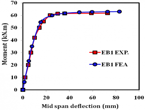
The ability of the numerical models to capture the bending moment-deflection behavior accurately is demonstrated by the good agreement between the experimental and numerical curves presented in Figure 5. As seen in Figure 6, the deformed styles of the beams produced by numerical modeling reasonably matched the corresponding experimental data.
Figure 5. Moment versus mid-span deflection relation of ECFST beam
Figure 6. Comparison of (top) experimental and (bottom) numerical failure modes for specimen EB1
After achieving satisfactory agreement between the results of the experiments and the numerical analysis, a parametric study using the validated FE models was performed, to assess the influence of steel tube thickness (t), Shear span to depth ratio (a/D), compressive strength of concrete ($f_{c}^{'})$, yielding strength of steel tube (${{f}_{y}})$, and aspect ratio D/B on the structural behavior of elliptical concrete filled steel tube beam. These parameters include material properties and geometric changes to investigate the influence these parameters on the structural behavior in term of moment capacity and strength index.
7.1 Influence of steel tube thickness
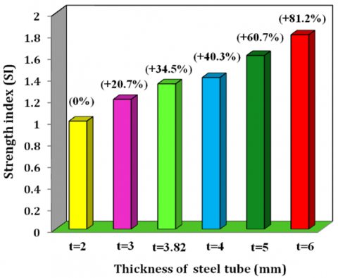
This study is conducted using the model on six ECFST beams to investigate the influence of thickness variation on the strength performance of beams. The moment carrying capacities and strength index in ECFST beams were studied. All analyzed ECFST beams have gross section of B=124 mm, D=192 mm, L equals to 2000 mm and thickness of steel tube (t) varies by 1 mm. Figure 7 and Table 2 manifestly indicate that the steel tube thickness has a significant effect on the resistances of ECFST beams. By increasing thickness of the steel tube from 2 mm to 6 mm, the bending moment increased by 81% because it is directly related to the metal tube’s rigidity and the delay of local buckling. To enhance the stiffness, it is much better to increase the steel tube thickness, due to the fact that the moment of inertia increases. For suitability of analysis, a strength index (SI, Eq. (3)) is defined to quantify the compressive strength as [25]:
$SI=\frac{{{M}_{ue}}}{{{M}_{ur}}}$ (3)
where,$~{{M}_{ue}}~$is the beam specimens average measured bending strength; ${{\text{M}}_{\text{ur}}}~$is the average bending strength of the ECFST beams used as reference, i.e. EBT2. Table 2 shows the determined strength indices (SI), and plotted in Figure 8 against thickness of steel tube (t). It can be found that SI increased with the increase of steel tube thickness, as shown in Figure 8.
Figure 7. Bending moment vs. deflection for various thickness
Figure 8. Effect of thickness on the strength index
The steel tube influence to concrete area ratio can be investigated depending on variation of thickness, where ${{\alpha }_{s}}$ is the steel tube to concrete area ratio (${{A}_{\text{s}}}$/${{A}_{c}}).$ The area of concrete (Eq. (4)):
${{A}_{c}}=\frac{\pi }{4}\left( 2a-2t \right)\left( 2b-2t \right)$ (4)
The area of steel tube (Eqs. (5) to (8)):
${{A}_{s}}=t~{{P}_{m}}$ (5)
${{P}_{m}}=\pi \left( {{a}_{m}}+{{b}_{m}} \right)\left( 1+\frac{3{{h}_{m}}}{10+\sqrt{4-3{{h}_{m}}}} \right)$ (6)
where,
${{a}_{m}}=\left( 2a-t \right)/2,~{{b}_{m}}=\left( 2b-t \right)/2$ (7)
${{h}_{m}}=\frac{{{\left( {{a}_{m}}-{{b}_{m}} \right)}^{2}}}{{{\left( {{a}_{m}}+{{b}_{m}} \right)}^{2}}}$ (8)
Table 2. Bending moment for different thickness of steel tube beam
|
Section Series |
$D$ |
$B$ |
$D/B$ |
$L$(mm) |
$t$(mm) |
D/t |
${{\alpha }_{s}}$ (%) |
$f_{c}^{'}$ (MPa) |
$fy$ (MPa) |
${{\mathbf{M}}_{\mathbf{FEA}}}$ |
$\Delta$ |
$\mathbf{SI}$ |
|
EBT2 |
192 |
124 |
1.5 |
2000 |
2 |
96.0 |
5.60 |
50 |
439.3 |
46.89 |
93.72 |
1 |
|
EBT3 |
192 |
124 |
1.5 |
2000 |
3 |
64.0 |
8.60 |
50 |
439.3 |
56.35 |
89.65 |
1.20 |
|
EBT3.8 |
192 |
124 |
1.5 |
2000 |
3.82 |
50.26 |
11.2 |
50 |
439.3 |
63.07 |
83.14 |
1.34 |
|
EBT4 |
192 |
124 |
1.5 |
2000 |
4 |
48.0 |
11.6 |
50 |
439.3 |
65.80 |
79.48 |
1.40 |
|
EBT5 |
192 |
124 |
1.5 |
2000 |
5 |
38.4 |
15.0 |
50 |
439.3 |
75.38 |
81.93 |
1.60 |
|
EBT6 |
192 |
124 |
1.5 |
2000 |
6 |
32.0 |
18.3 |
50 |
439.3 |
84.95 |
74.74 |
1.81 |
From equations above, it is clear that the variation of steel tube to concrete area ratios depend basically on variation of steel tube thickness (where a and b are constants). From Table 2 can be showed that by increasing steel tube to concrete area ratio from 5.6% to 18.3% the moment carrying capacity increased by 81%.
7.2 Influence shear span to depth ratio
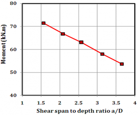
Shear span to depth ratio is the distance between the point of concentrated load (a) and a support to depth of gross section (D). This ratio affected on the load-carrying mechanism of the flexural member. The influence of shear span to depth ratio on ECFST beam for different a/D ratios is observed as shown in Figure 9. The bending moment increases by 8%, 17%, 24%, and 33% at a/D = 3.13, 2.56, 2.05, and 1.5, respectively as shown in Table 3. As the shear span to depth ratio (a/D) decreases, the bending moment increases.
The increase in strength is significant in ECFST beams as a/D decrease because a significant portion of the shear may be transmitted directly to the support by an inclined strut. It is the ratio of shear span to depth has a relatively small impact on the curves as shown in Figure 9. The moment is maximum at a/D = 1.5 for all a/D ratios considered. It also indicates from Figure 10 that the strength index increases with the increase in a/D. Figure 11 demonstrates the effects of shear span to depth ratio on the bending moment. It is observed that the bending moment decreases with the increase in the a/D ratio.
Figure 9. Bending moment vs. mid-span deflection for various a/D ratios
Figure 10. Effect a/D ratios on the strength index (SI)
Figure 11. Effect of a/D ratios on the bending moment
7.3 Influence of yielding stress of steel tube
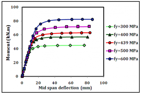
Group of ECFST beams presented in Table 4, were examined to see how different steel strengths affected how they perform. As shown in Table 4 all other parameters are constants. The bending moment-mid span deflection responses for ECFST beams with various strengths are demonstrated in Figure 12. It is shown that when the yield strength of steel tubes rises, so does the bending moment of elliptical CFST beams. If the steel tube yield strength is changed from 300 MPa to 600 MPa, bending moment capacity increases by 83%.
Figure 12. Bending moment vs. mid-span deflection for various yielding stress of steel
Figure 13. Effect yielding stress on the strength index
Figure 14. Effect of yielding stress on the bending moment
This demonstrates how using high strength steel tubes could greatly boost the moment capacity of an ECFST beam. Steel yield strengths' impacts on the strength index are displayed in Figure 13. It seems that the strength performance of ECFST beams is much enhanced by the use of high strength steel tubes. Figure 14 demonstrates the effects of yielding stress on the bending moment. It is observed that the bending moment increases with an increase in the yielding stress of steel tube.
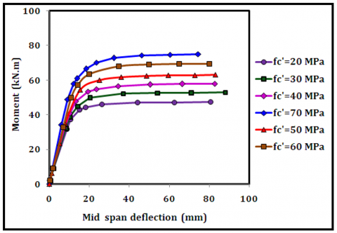
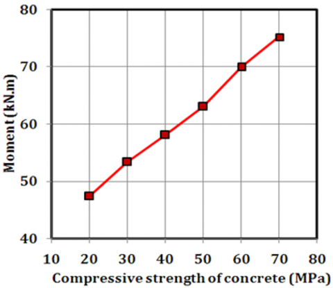
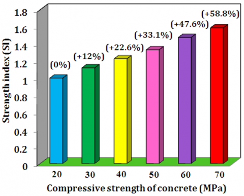
7.4 Effect of concrete compressive strength
Group of ECFST beams were analyzed in which strength of concrete changing from 20 MPa to 70 MPa while other parameters are D/B = 1.5, L = 2000mm, a/D = 2.56, t = 3.28 mm, and fy = 439.3 MPa constants as shown in Table 5. Figure 15 depicts the moment – mid span deflection behavior for elliptical CFBST beams having different concrete strengths. When the strength of the concrete increases, so does the bending strength as shown in Figure 15. The bending strength of ECFST beams is enhanced about 59% by increase in compressive strength from 20 to 70 MPa. The results, as illustrated in Figure 16, show that raising the concrete's compressive strength raises the ECFST beams' strength index. Figure 17 shows the impacts of the compressive strengths of concrete on the bending moment. It is observed that the bending moment of an elliptical CFST beam increases with an increase in the compressive strength of filled concrete.
Table 3. Bending moment for ECFST beams with different shear span to depth ratio
|
Section Series |
$D$ |
$B$ |
$D/B$ |
$L$ (mm) |
$a/D$ |
$t$ (mm) |
$f_{c}^{'}$ (MPa) |
$fy$ (MPa) |
${{\mathbf{M}}_{\mathbf{FEA}}}$ |
$\Delta$ |
$\mathbf{SI}$ |
|
E3.65T3.82 |
192 |
124 |
1.5 |
2000 |
3.65 |
3.82 |
50 |
439.3 |
53.70 |
73.11 |
1.00 |
|
E3.13T3.82 |
192 |
124 |
1.5 |
2000 |
3.13 |
3.82 |
50 |
439.3 |
58.02 |
77.47 |
1.08 |
|
E2.6T3.82 |
192 |
124 |
1.5 |
2000 |
2.56 |
3.82 |
50 |
439.3 |
63.07 |
83.14 |
1.17 |
|
E2.08T3.82 |
192 |
124 |
1.5 |
2000 |
2.05 |
3.82 |
50 |
439.3 |
66.83 |
73.22 |
1.24 |
|
E1.56T3.82 |
192 |
124 |
1.5 |
2000 |
1.5 |
3.82 |
50 |
439.3 |
71.53 |
83.37 |
1.33 |
Table 4. Bending moment for ECFST beams with different yielding stress of steel tube
|
Section Series |
$D$ |
$B$ |
$D/B$ |
$L$ (mm) |
$a/D$ |
$t$ (mm) |
D/t |
$f_{c}^{'}$ (MPa) |
$fy$ (MPa) |
${{\mathbf{M}}_{\mathbf{FEA}}}$ |
$\Delta$ |
$\mathbf{SI}$ |
|
E1.5FY300 |
192 |
124 |
1.5 |
2000 |
2.56 |
3.82 |
50.3 |
50 |
300 |
44.82 |
76.25 |
1 |
|
E1.5FY400 |
192 |
124 |
1.5 |
2000 |
2.56 |
3.82 |
50.3 |
50 |
400 |
56.95 |
80.22 |
1.27 |
|
E1.5FY439 |
192 |
124 |
1.5 |
2000 |
2.56 |
3.82 |
50.3 |
50 |
439.3 |
63.07 |
83.14 |
1.40 |
|
E1.5FY500 |
192 |
124 |
1.5 |
2000 |
2.56 |
3.82 |
50.3 |
50 |
500 |
71.89 |
82.36 |
1.60 |
|
E1.5FY600 |
192 |
124 |
1.5 |
2000 |
2.56 |
3.82 |
50.3 |
50 |
600 |
82.12 |
86.22 |
1.83 |
Table 5. Bending moment for ECFST beams with different compressive strength of concrete
|
Section Series |
$D$ |
$B$ |
$D/B$ |
$L$ (mm) |
$a/D$ |
$t$ (mm) |
$f_{c}^{'}$ (MPa) |
$fy$ (MPa) |
${{\mathbf{M}}_{\mathbf{FEA}}}$ |
$\Delta$ |
$\mathbf{SI}$ |
|
E1.5FY300 |
192 |
124 |
1.5 |
2000 |
2.56 |
3.82 |
20 |
439.3 |
47.39 |
80.78 |
1.00 |
|
E1.5FY400 |
192 |
124 |
1.5 |
2000 |
2.56 |
3.82 |
30 |
439.3 |
53.37 |
88.08 |
1.12 |
|
E1.5FY439 |
192 |
124 |
1.5 |
2000 |
2.56 |
3.82 |
40 |
439.3 |
58.08 |
82.74 |
1.23 |
|
E1.5FY500 |
192 |
124 |
1.5 |
2000 |
2.56 |
3.82 |
50 |
439.3 |
63.07 |
83.14 |
1.33 |
|
E1.5FY600 |
192 |
124 |
1.5 |
2000 |
2.56 |
3.82 |
60 |
439.3 |
69.93 |
80.22 |
1.48 |
|
E1.5FY600 |
192 |
124 |
1.5 |
2000 |
2.56 |
3.82 |
70 |
439.3 |
75.24 |
88.71 |
1.59 |
Figure 15. Bending moment vs. mid-span deflection for various compressive strength of concrete
Figure 16. Effect compressive strength on the strength index
Figure 17. Effect of compressive strength on the moment
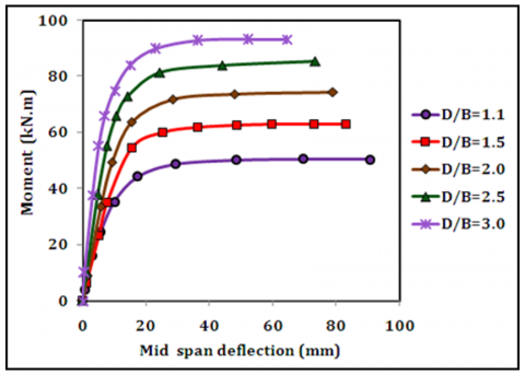
7.5 Effect of depth to width ratio
Five samples of ECFST beams are analyzed using FEA software to study the effect of depth to width ratio of elliptical CFST beams (with constant area) on the bending moment -mid span deflection behavior of beams and their ultimate bending moments are examined here. A different ratio of depth to width for ECFST beams were taken in the finite element analysis. The selected ratios (D/B) were (1.1, 1.5, 2.0, 2.5 and 3.0). By choosing these ratios, the total area of ECFST was kept constant as listed in Table 6. Finite element mesh for all cases is illustrated in Figure 18. Figure 19 shows relation of bending moment-mid span deflection behavior of selected beam.
When the D/B ratio of the cross section is increased from 1.1 to 3.0, bending moment capacity increases by 85%. Figure 20 shows that increasing the D/B ratio increases the strength index of ECFST beams. The relationship between the depth to width ratio and the bending moment is depicted in Figure 21. As the ratio grew, there was a noticeable increase in the ultimate moment.
For the purpose of design recommendation, Figure 22 was developed. The trend of strength index for the variation in each parameter shows the possibility of further improvement in the structural behavior of the specimens. The most effective parameter was the depth to width ratio, yield of steel, and thickness of tube respectively. Depending on the economic aspects, the designer can decide which parameter can improve the structural behavior with minimal cost.
Figure 18. Finite element mesh for various depths to width ratio
Table 6. Bending moment for ECFST beams with different depth to width ratio
|
Section Series |
$D$ |
$B$ |
$D/B$ |
$L$ (mm) |
$a/D$ |
$t$ (mm) |
$f_{c}^{'}$ (MPa) |
$fy$ (MPa) |
${{\mathbf{M}}_{\mathbf{FEA}}}$ |
$\Delta$ |
$\mathbf{SI}$ |
|
E1.5FY300 |
161.7 |
147 |
1.1 |
2000 |
2.56 |
3.82 |
50 |
439.3 |
50.39967 |
90.62 |
1.00 |
|
E1.5FY400 |
192 |
124 |
1.5 |
2000 |
2.56 |
3.82 |
50 |
439.3 |
63.0721 |
83.14 |
1.25 |
|
E1.5FY439 |
218 |
109 |
2.0 |
2000 |
2.56 |
3.82 |
50 |
439.3 |
75.9906 |
78.85 |
1.51 |
|
E1.5FY500 |
234.8 |
97.5 |
2.5 |
2000 |
2.56 |
3.82 |
50 |
439.3 |
85.371 |
73.41 |
1.64 |
|
E1.5FY600 |
267 |
89 |
3.0 |
2000 |
2.56 |
3.82 |
50 |
439.3 |
93.2114 |
64.25 |
1.85 |
Figure 19. Bending moment vs. mid-span deflection for various depth to width ratio
Figure 20. Effect D/B on the strength index
Figure 21. Effect of D/B on the bending moment
Figure 22. Strength indices for various parameters
For the results obtained through the using of ANN Table 7 shows the statistical analysis for the correlation coefficient and, mean square error and normalized root mean square error. This analysis showed a good prediction for the moment with overall correlation coefficient of 0.985 but the normalized root mean square error was in range of (0.043 to 0.185). Figure 23 reveals the good divergence for the predicted moment using ANN with the moment obtained from the FEM method.
Table 7. Statistical description for ANN results with respect to FEM
|
Cases |
R2 |
MSQR |
NRMSE |
Total R2 |
|
Case 1 |
0.994808 |
1.564753 |
0.139164 |
0.985137 |
|
Case 2 |
0.977476 |
1.937767 |
0.10868 |
|
|
Case 3 |
0.995254 |
1.634715 |
0.043826 |
|
|
Case 4 |
0.985975 |
2.095796 |
0.185792 |
|
|
Case 5 |
0.988066 |
3.224838 |
0.075326 |
From other hand, the predicted results through using SVM comes with high correlation coefficient (0.983) with minimal variation for the five cases under consideration, also Table 8 states that the normalized root mean square error was (0.049 to 0.088), this rang reflect the high stability of the predicted model. Figure 24 shows very high divergence for the SVM predicted moment with the FEM results.
Table 8. Statistical description for SVM results with respect to FEM
|
Cases |
R2 |
MSQR |
NRMSE |
Total R2 |
|
Case 1 |
0.972398 |
3.23858 |
0.085091 |
0.982964 |
|
Case 2 |
0.993872 |
1.212189 |
0.067986 |
|
|
Case 3 |
0.997243 |
1.841374 |
0.049367 |
|
|
Case 4 |
0.997377 |
2.475096 |
0.088872 |
|
|
Case 5 |
0.992987 |
1.935568 |
0.045211 |
Figure 23. Predicted moment using ANN results with respect to FEM
Figure 24. Predicted moment using SVM results with respect to FEM
The behavior of confined concrete has been recognized to be changed based on the confinement section's boundary conditions. For ECFST tubular section, the contact interaction surface between the steel tube and the concrete core showed consistent restriction. Therefore, the overall confinement effect and the confining force distribution throughout the tube's perimeter may be influenced by the hollow section's shape, dimensions, and material qualities, this will cause the infill concrete's confinement effect to change and result in different behavior of elliptical tubular composite beam.
Numerical nonlinear analytical model based on the Finite Element Method (FEM) was created using the ANSYS computer program to examine the impact of various parameters on the bending moment-deflection response over the full behavioral range. The main conclusions were as following:
As a final conclusion, the integration of numerical analysis with artificial intelligent techniques serve to overcome the obstacle of the need to heavy experimental work and its high cost, providing of suitable sets of required data to train the artificial models, and the possibility of investigating a wide range of cases for each parameter. Moreover, there is a saving in cost, time and efforts for studying different cases of composite structures. For further development, many areas still need for further investigation and modelling, such as the connections of beam with other structural members, fire resistance of ECFST beam, and the possibility of utilizing the deep learning tools and decision tree techniques to model these cases.
|
ECFST |
Elliptical Concrete Filled Steel Tubular |
|
EHS |
elliptical hollow section |
|
S, R, C-HS |
Square, Rectangular, Circular, Hollow Section |
|
$f_{c}^{'}$ |
Concrete Compressive Strength, MPa. |
|
$fy$ |
Yielding Strength of Steel, MPa. |
|
ANN$~$ |
Artificial Neural Network |
|
AI |
Artificial Intelligent |
|
EHS |
Elliptical Hollow Section |
|
SVM |
Support Vector Machine |
|
fu |
Ultimate Strength of Steel, MPa. |
|
${{E}_{s}}$ |
Modulus of Elasticity of Steel, GPa |
|
${{E}_{c}}$ |
Modulus of Elasticity of Concrete, GPa |
|
SI |
Strength Index |
|
${{M}_{ue}}$ |
Average Bending Strength of beam specimens |
|
${{\text{M}}_{\text{ur}}}$ |
Average Bending Strength of ECFST beams |
|
NMSRE |
normalized mean square root error |
|
NMSRD |
normalized mean square root deviation |
|
a/D |
Shear span to depth ratio |
|
t |
steel tube thickness |
|
FE |
Finite element |
|
${{A}_{\text{s}}}$/${{A}_{c}}$ |
steel tube to concrete area ratio |
|
L, B |
Length and width of beam |
|
${{P}_{m}}$ |
steel tube surface area |
|
${{a}_{m}},{{b}_{m}}$ |
Radiuses of steel tube |
|
${{h}_{m}}$ |
Length of steel tube |
|
Greek symbols |
|
|
Δ |
Lateral Displacement, mm |
[1] Packer, J.A. (2008). Going elliptical. Modern Steel Construction, American Institute of Steel Construction, 48(3): 65-67.
[2] Silvestre, N., Pires, T., Duarte, A.P. (2013). Numerical analysis of semi-elliptical hollow section columns. Proceedings of the Institution of Civil Engineers-Structures and Buildings, 166(8): 424-433. https://doi.org/10.1680/stbu.12.00065
[3] Chan, T.M., Gardner, L. (2008). Compressive resistance of hot-rolled elliptical hollow sections. Engineering structures, 30(2): 522-532. https://doi.org/10.1016/j.engstruct.2007.04.019
[4] Chan, T.M., Gardner, L. (2008). Bending strength of hot-rolled elliptical hollow sections. Journal of Constructional Steel Research, 64(9): 971-986. https://doi.org/10.1016/j.jcsr.2007.11.001
[5] Chan, T.M., Gardner, L. (2009). Flexural buckling of elliptical hollow section columns. Journal of Structural Engineering, 135(5): 546-557. https://doi.org/10.1061/(asce)st.1943-541x.0000005
[6] Ruiz-Teran, A.M., Gardner, L. (2008). Elastic buckling of elliptical tubes. Thin-Walled Structures, 46(11): 1304-1318. https://doi.org/10.1016/j.tws.2008.01.036
[7] Law, K.H., Gardner, L. (2012). Lateral instability of elliptical hollow section beams. Engineering structures, 37: 152-166. https://doi.org/10.1016/j.engstruct.2011.12.008
[8] Law, K.H., Gardner, L. (2013). Buckling of elliptical hollow section members under combined compression and uniaxial bending. Journal of Constructional Steel Research, 86: 1-16. https://doi.org/10.1016/j.jcsr.2013.03.008
[9] Silvestre, N., Gardner, L. (2011). Elastic local post-buckling of elliptical tubes. Journal of Constructional Steel Research, 67(3): 281-292. https://doi.org/10.1016/j.jcsr.2010.11.004
[10] McCann, F., Fang, C., Gardner, L., Silvestre, N. (2016). Local buckling and ultimate strength of slender elliptical hollow sections in compression. Engineering Structures, 111: 104-118. https://doi.org/10.1016/j.engstruct.2015.12.020
[11] Uenaka, K. (2014). Experimental study on concrete filled elliptical/oval steel tubular stub columns under compression. Thin-Walled Structures, 78: 131-137. https://doi.org/10.1016/j.tws.2014.01.023
[12] Liu, F., Wang, Y., Chan, T.M. (2017). Behaviour of concrete-filled cold-formed elliptical hollow sections with varying aspect ratios. Thin-Walled Structures, 110: 47-61. https://doi.org/10.1016/j.tws.2016.10.013
[13] Yang, H., Lam, D., Gardner, L. (2008). Testing and analysis of concrete-filled elliptical hollow sections. Engineering Structures, 30(12): 3771-3781. https://doi.org/10.1016/j.engstruct.2008.07.004
[14] Abubakar, S.M., Audu, I., Victor, O.W., Adeboye, K.R. (2013). A conceptual Nigeria stock exchange prediction: Implementation using support vector machines-SMO model. World of Computer Science and Information Technology Journal, 3(4): 85-90.
[15] Yaseen, Z.M., Deo, R.C., Hilal, A., Abd, A.M., Bueno, L.C., Salcedo-Sanz, S., Nehdi, M.L. (2018). Predicting compressive strength of lightweight foamed concrete using extreme learning machine model. Advances in Engineering Software, 115: 112-125. https://doi.org/10.1016/j.advengsoft.2017.09.004
[16] Zhao, X.L., Packer, J.A. (2009). Tests and design of concrete-filled elliptical hollow section stub columns. Thin-Walled Structures, 47(6-7): 617-628. https://doi.org/10.1016/j.tws.2008.11.004
[17] Uenaka, K., Tsunokake, H. (2016). Concrete filled elliptical steel tubular members with large diameter-to-thickness ratio subjected to bending. Structures Elsevier 5: 58-66. https://doi.org/10.1016/j.istruc.2015.08.004
[18] Jamaluddin, N., Lam, D., Dai, X.H., Ye, J. (2013). An experimental study on elliptical concrete filled columns under axial compression. Journal of Constructional Steel Research, 87: 6-16. https://doi.org/10.1016/j.jcsr.2013.04.002
[19] McCann, F., Gardner, L., Qiu, W. (2015). Experimental study of slender concrete-filled elliptical hollow section beam-columns. Journal of Constructional Steel Research, 113: 185-194. https://doi.org/10.1016/j.jcsr.2015.06.013
[20] Espinos, A., Romero, M.L., Portolés, J.M., Hospitaler, A. (2014). Ambient and fire behavior of eccentrically loaded elliptical slender concrete-filled tubular columns. Journal of Constructional Steel Research, 100: 97-107. https://doi.org/10.1016/j.jcsr.2014.04.025
[21] Sheehan, T., Dai, X.H., Chan, T.M., Lam, D. (2012). Structural response of concrete-filled elliptical steel hollow sections under eccentric compression. Engineering Structures, 45: 314-323. https://doi.org/10.1016/j.engstruct.2012.06.040
[22] Dai, X., Lam, D. (2010). Numerical modelling of the axial compressive behaviour of short concrete-filled elliptical steel columns. Journal of Constructional Steel Research, 66(7): 931-942. https://doi.org/10.1016/j.jcsr.2010.02.003
[23] Dai, X.H., Lam, D., Jamaluddin, N., Ye, J. (2014). Numerical analysis of slender elliptical concrete filled columns under axial compression. Thin-Walled Structures, 77: 26-35. https://doi.org/10.1016/j.tws.2013.11.015
[24] Mahgub, M., Ashour, A., Lam, D., Dai, X. (2017). Tests of self-compacting concrete filled elliptical steel tube columns. Thin-Walled Structures, 110: 27-34. https://doi.org/10.1016/j.tws.2016.10.015
[25] Qiu, W., McCann, F., Espinos, A., Romero, M.L., Gardner, L. (2017). Numerical analysis and design of slender concrete-filled elliptical hollow section columns and beam-columns. Engineering Structures, 131: 90-100. https://doi.org/10.1016/j.engstruct.2016.10.024
[26] Law, K.H., Gardner, L. (2012). Lateral instability of elliptical hollow section beams. Engineering Structures, 37: 152-166. https://doi.org/10.1016/j.engstruct.2011.12.008
[27] Ren, Q.X., Han, L.H., Lam, D., Li, W. (2014). Tests on elliptical concrete filled steel tubular (CFST) beams and columns. Journal of Constructional Steel Research, 99: 149-160. https://doi.org/10.1016/j.jcsr.2014.03.010
[28] Mander, J.B., Priestley, M.J., Park, R. (1988). Theoretical stress-strain model for confined concrete. Journal of Structural Engineering, 114(8): 1804-1826. https://doi.org/10.1061/(ASCE)0733-9445(1988)114:8(1804)
[29] Pendharkar, U., Chaudhary, S., Nagpal, A.K. (2007). Neural network for bending moment in continuous composite beams considering cracking and time effects in concrete. Engineering Structures, 29(9): 2069-2079. https://doi.org/10.1016/j.engstruct.2006.11.009
[30] Kaczmarek, M., Szymańska, A. (2016). Application of artificial neural networks to predict the deflections of reinforced concrete beams. Studia Geotechnica et Mechanica, 38(2): 37-46. https://doi.org/10.1515/sgem-2016-0017
[31] Ochmański, M., Bzówka, J. (2012). Back analysis of SCL tunnels based on artificial neural network. Architecture, Civil Engineering, Environment–ACEE Journal, 5(3): 73-82.
[32] Guzelbey, I.H., Cevik, A., Gögüş, M.T. (2006). Prediction of rotation capacity of wide flange beams using neural networks. Journal of Constructional Steel Research, 62(10): 950-961. https://doi.org/10.1016/j.jcsr.2006.01.003
[33] Abd, A.M., Abd, S.M. (2014). Neuro-fuzzy model to evaluate ready-mix concrete properties. International Journal of Engineering Research and Science and Technology, 3(1): 24-33.
[34] Abd, A.M., Abd, S.M. (2017). Modelling the strength of lightweight foamed concrete using support vector machine (SVM). Case Studies in Construction Materials, 6: 8-15. https://doi.org/10.1016/j.cscm.2016.11.002
[35] van Ruijven, B., van der Sluijs, J.P., van Vuuren, D.P., Janssen, P., Heuberger, P.S., de Vries, B. (2010). Uncertainty from model calibration: Applying a new method to transport energy demand modelling. Environmental Modeling & Assessment, 15: 175-188. https://doi.org/10.1007/s10666-009-9200-z