Experimental and Mathematical Analysis of the Performance of a Small Scale Absorption Cycle (NH3-H2O and LiBr-H2O)

Nabeel Abu Shaban*![]() | Mai Bani Younes
| Mai Bani Younes![]() | Shahnaz Alkhalil
| Shahnaz Alkhalil![]()
© 2024 The authors. This article is published by IIETA and is licensed under the CC BY 4.0 license (http://creativecommons.org/licenses/by/4.0/).
OPEN ACCESS
Air conditioning plays a vital role in modern life, but its high energy consumption, particularly in vapor compression cycles, is a major concern. This study explores absorption cycles as an alternative, where the compressor is replaced with components powered by heat instead of electricity, potentially leading to reduce energy consuming. The study has three main approaches: theoretical analysis, experimental and validation. The theoretical analysis uses Engineering Equation Solver (EES) to model the system's performance, focusing on Coefficient of Performance (COP) and cooling capacity, for two working pairs NH3-H2O and LiBr-H2O. The experimental setup was designed to validate the theoretical model. The results from the theoretical analysis show good agreement with a maximum deviation of around 0.6%. Furthermore, the analysis indicates that the LiBr-H2O pair has better COP and cooling capacity than NH3-H2O by approximately 33%. This suggests that LiBr-H2O absorption cycles have the potential to be a more efficient and sustainable alternative for air conditioning systems.
absorption cycle, Engineering Equation Solver (EES), cooling capacity, renewable energy, LiBr-H2O, NH3-H2O, air conditioning
1.1 Absorption cycle
Thermal management in cold storage warehouses is crucial for product quality, but maintaining low temperatures often comes at a high energy cost, especially in hot climates. Vapor compression systems, the traditional workhorse for air conditioning and refrigeration, rely on electrical power generated from fossil fuels, contributing to significant CO2 emissions [1-3].
Absorption cooling systems, powered by renewable energy sources like solar or geothermal, offer a more environmentally friendly alternative [4]. These systems utilize working pairs like lithium bromide-water (LiBr-H2O) or ammonia-water (NH3-H2O) [5, 6]. While absorption systems boast lower operating costs and environmental impact, their initial cost can be higher, and their COP may be lower compared to traditional systems [7-14].
This study aims to investigate the performance of absorption cooling systems through theoretical modeling and experimental validation. We will develop a model using EES software to analyze the COP under various operating conditions. We will then construct an experimental setup to validate the model's predictions and identify the optimal COP under worst-case scenarios. Furthermore, we will compare the performance of NH3-H2O and LiBr-H2O absorption systems to determine which is better suited for specific applications.
1.2 System description
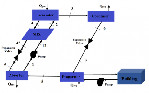
The proposed absorption system has many components, including an absorption cycle, an evaporator, an absorber, a generator, a condenser, a heat exchanger, expansion valves for refrigerant and solution, and a pump, as illustrated in Figure 1.
A great temperature heating fluid, heated by any source of heat, is used in the generator. Through the heat exchanger, a relatively weak solution (2) leaves the absorber and enters the generator. The solution absorbs heat by the heating source after heat exchange with it inside the generator, allowing the refrigerant to boil out and separate from the solution at high pressure. After separation, evaporation removes the refrigerant produced (3) from the solution. The concentrated solution is emitted by the generator. For reheating, hot fluid returns to the heating source. The refrigerant (3) that exits the generator is totally vapour with no liquid present. At state (3), high-temperature, high-pressure refrigerant enters the condenser. The refrigerant (3) condenses inside the condenser by transferring heat to the condenser cooling medium. The condensed refrigerant then leaves as liquid refrigerant (6), which passes through a throttling valve and expands. While flowing through the expansion mechanism, the pressure of the refrigerant reduces to that of the evaporator. The temperature is further decreased throughout the throttling component. Thus, the desired cooling load could be achieved at the required evaporator pressure and temperature. To achieve the appropriate cooling effect, heat from the zone is absorbed inside the evaporator. The conditioned zone's heat is absorbed by the refrigerant that is sprayed there (7) and then cooled to the proper temperature. The evaporator's saturated refrigerant (8) goes to the absorber. While the concentrated solution leaves the generator (4), flows through the throttling valve and heat exchanger (45 and 5), respectively. After that, the absorber is received the sprayed strong solution (5). When low pressure refrigerant (8) comes into mixes with a reduced temperature of the strong solution (5), the strong solution (5) is diluted inside the absorber (1). The absorber's pressure is reduced by refrigerant absorption in the strong solution, which draws additional refrigerant from the evaporator and increases the temperature of the solution. To remove the heat generated by mixing the refrigerant with the strong solution, cooling medium (air or water) flows within the absorber. To complete the cycle, dilute solution (1) is pumped into the generator via the heat exchanger after the absorption process. The weak solution is then gaining inside the heat exchanger and the temperature of the strong solution is reduced.
Figure 1. Absorption cycle schematic diagram
1.3 Literature review
Several theoretical and experimental research have been conducted especially in recent years to establish the notion of combined different heating sources with absorption systems [15-21]. Lubis et al. [15] studied the performance coefficient of a different configurations of LiBr-H2O absorption system for Asian climates driven using combined solar and gas energy. They found that using cold (28-34℃) and hot (75-90℃) water, they could save energy 60%, and the COP range is 1.4-3.3. Bellos et al. [16] used flat plate collectors to investigate H2O-LiBr and H2O-LiCl pairs, in an absorption system. They looked at 3 distinct ambient temperatures, they found that the lithium chloride-water system exceeds the H2O-LiBr system in all of cases, with its maximum running temperature being lower than the H2O-LiBr system. Recently, Bellos et al. [17] investigated the exergy and energy analysis of 100kW H2O-LiBr absorption cycle combined to several collector configurations and reported the influences of collector temperature on exergetic efficiency, COP, and solar absorption system running cost. Parabolic trough collectors have more efficiency from an exegetic and energetic standpoint, but they demand more investment, whereas evacuated tube collectors require less investment and space. In Athens, Greece, Bellos et al. [18] performed simulation for solar absorption system (single stage lithium bromide-water) with evacuated tube collectors. They adjusted the storage tank size from 6 to 16 m3 and the ETC's area range is 150 to 600 m2 and discovered that a 450 m2 of ETCs and a 14 m3 storage tank which is one of the best preferred configurations designs, with a 15-year payback period. Yadav et al. [19] studied an absorption cycle with an evacuated tube collectors’ simulation. The COP was within the range of 0.46 to 0.78 for temperatures of generator range 54.4℃ to 71.1℃, according to the scientists.
The main aim of this study is to develop a theoretical and experimental investigations for the absorption cycle after doing the validation with an existing experimental data. The model will be developed using EES coding. Different operating parameters will be used to examine the COP by conducting different parametric analysis. Experimental setup will be constructed to investigate the COP and compare it with the modelling analysis and the optimum COP will be specified at the worst conditions. Finally, a comparison study will be made between the performance of the systems that works using NH3-H2O and LiBr-H2O.
There are several assumptions are made to simplify the model's subsequent implementation:
The essential equations that describe the operation of an absorption cooling system are described in this paragraph. The evaporator's energy balance is:
The single-stage absorption cooling cycle is simulated, and for each component, the following steady-state mass and energy balance equations are developed.
The mass flow rate is represented by $m^{\cdot}$ in Eq. (1), and the inlet and outlet values are denoted by in and out, accordingly.
$\sum \dot{m}_{\text {in }}=\sum \dot{m}_{\text {out }}$ (1)
Eq. (2) provides a generic formula for the energy balance.
$\dot{Q}+\sum \dot{m}_{\text {in }} * h_{\text {in }}=\dot{W}+\sum \dot{m}_{\text {out }} * h_{\text {out }}$ (2)
where, the overall amount of input heat is $\dot{Q}$, the overall amount of output work is $\dot{W}$, the inlet enthalpy is $h_{i n}$ and the exit enthalpy is $h_{\text {out }}$.
$\dot{Q}=\dot{Q}_{\text {in }}-\dot{Q}_{\text {out }}$ (3)
$\dot{W}=\dot{W}_{\text {in }}-\dot{W}_{\text {out }}$ (4)
The following equations illustrate the mass and energy balance at the absorber:
$\dot{m}_{s s}=\dot{m}_{w s}+\dot{m}_r$ (5)
$\dot{m}_{w s}=\lambda \dot{m}_r$ (6)
$\dot{m}_{s s}=(1+\lambda) \dot{m}_r$ (7)
$\dot{m}_r+\left(1-X_{w s}\right) * \dot{m}_{w s}=\left(1-X_{s s}\right) \dot{m}_{s s}$ (8)
$\lambda=\frac{X_{s s}}{X_{w s}-X_{s s}}$ (9)
$\dot{Q}_{a b s}=\dot{m}_r \quad\left[\left(h_8-h_1\right)+\lambda\left(h_5-h_1\right)\right]$ (10)
where, $\mathrm{X}$ is the solution concentration, $\mathrm{r}$ is the refrigerant, $\lambda$ is the circulation ratio, and SS and WS are the strong and weak solutions, respectively. The energy balance of the generator, evaporator, and condenser is shown by the following equations:
$\dot{m}_3=\dot{m}_6=\dot{m}_r$ (11)
$\dot{Q}_{c o n}=\dot{m}_r *\left(h_3-h_6\right)$ (12)
$\dot{m}_8=\dot{m}_7=\dot{m}_r$ (13)
$\dot{Q}_{\text {eva }}=\dot{m}_r *\left(h_8-h_7\right)$ (14)
$\dot{m}_2=\dot{m}_4+\dot{m}_3$ (15)
$\dot{m}_{s s} * X_{s s}=\left(\dot{m}_{w s} * X_{w s}+\dot{m}_r * X_r\right)$ (16)
$\dot{Q}_{g e n}=\dot{m}_r \quad\left[\left(h_3-h_4\right)-\lambda\left(h_2-h_4\right)\right]$ (17)
The energy balance, effectiveness, and solution and refrigerant expansion valves may be represented by the following equations:
$\dot{m}_{45}=\dot{m}_5=\dot{m}_{w s}$ (18)
$h_{45}=h_5$ (19)
$\dot{m}_6=\dot{m}_7=\dot{m}_r$ (20)
$h_6=h_7$ (21)
The mass balance, energy balance, and effectiveness of the solution heat exchanger may be explained by the following equations:
$\dot{m}_{45}=\dot{m}_4=\dot{m}_{s s}$ (22)
$\dot{m}_2=\dot{m}_{12}=\dot{m}_{w s}$ (23)
$\dot{Q}_{S H X}=\dot{m}_r \quad \lambda\left(h_4-h_{45}\right)$ (24)
$\varepsilon_{S H X}=\frac{T_4-T_{45}}{T_4-T_{12}}$ (25)
The following equations illustrate the mass and energy balance at the pump:
$\dot{m}_1=\dot{m}_{12}$ (26)
$\dot{W}_p=\dot{m}_1 \quad\left(h_{12}-h_1\right)$ (27)
The cooling effect performance is measured by the COP, which is described as:
$C O P_c=\frac{Q_{e v a}}{Q_{\text {gen }}+\dot{W}_p}$ (28)
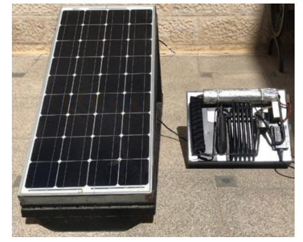
The absorption chiller setup, built as shown in Figure 2, utilizes an NH3-H2O solution as the working pair. Solar energy (collector) is used as a heat source to operate the generator.
The system is equipped with a control system that monitors and regulates various parameters such as temperatures, pressures, and flow rates. After taking the data from the ammonia system, the system is rebuilt, manufactured, and maintained to operate using LiBr-H2O. In this study, the two systems are compared in terms of better performance and higher cooling capacity.
Figure 2. The absorption chiller setup
In this section, the results will be presented and discussed after validating the mathematical model with the experimental model. The validation of the mathematical model with the experimental data and the results are presented and discussed as following.
4.1 Validation results
The theoretical results are validated with the experimental results so that the deviation between them is small which the maximum deviation that’s indicated is almost 0.6%, and this indicates that the system is valid. Table 1 shows the comparison at Ta=33℃, Tc=45.8℃ and Te=6℃. inputs, the pair used in this comparison is LiBr-H2O.
Table 1. Validation results for the COP at Ta=33℃, Tc=45.8℃ and Te=6℃
|
Tg [℃] |
COPExp |
COPTh |
COP Deviation |
Percentage Error |
|
84 |
0.775 |
0.78 |
0.0050 |
0.65% |
|
86 |
0.783 |
0.788 |
0.0050 |
0.64% |
|
88 |
0.786 |
0.791 |
0.0050 |
0.64% |
|
90 |
0.797 |
0.791 |
0.0060 |
0.75% |
|
92 |
0.797 |
0.791 |
0.0060 |
0.75% |
|
94 |
0.795 |
0.789 |
0.0060 |
0.75% |
|
96 |
0.791 |
0.787 |
0.0040 |
0.51% |
|
98 |
0.789 |
0.785 |
0.0040 |
0.51% |
|
100 |
0.786 |
0.782 |
0.0040 |
0.51% |
4.2 Theoretical and experimental results
The effect of changing operating circumstances on the system's performance metrics (COP and cooling capacity) is explored in this section. Since ambient temperatures fluctuate throughout the year, it's natural for the operating temperatures of the absorption cycle components to change as well.
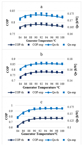
Figure 3 demonstrates how varying the generator temperature affects cooling capacity (Qe) and COP for various LiBr-H2O evaporator temperatures.
As expected, an increase in generator temperature leads to a rise in Qe and COP. This is because higher generator temperatures enhance the evaporation of the refrigerant within the generator. However, performance starts to decline when the generator temperature surpasses 90℃, indicating this as the optimal operating temperature.
The figure also shows a decrease in performance parameters with lower evaporator temperatures, with 6℃ being the most favorable temperature in this case.
Figure 3. The effect of changing the generator temperature on the COP and the Qe at Ta=33℃, Tc=45.8℃, and a) Te=6℃, b) Te=4℃, and c) Te=2℃
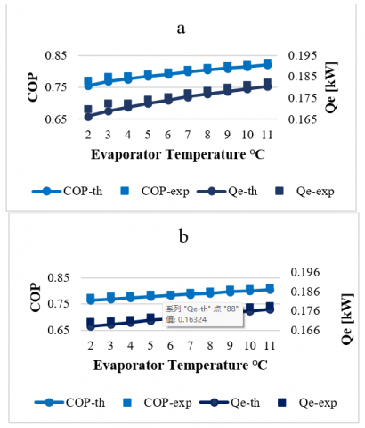
In Figure 4, the effect of changing the evaporator temperature on the performance parameters at different temperatures of the generator is studied. The figure shows a clearer detail of the effect of changing the evaporator temperature on the performance parameters.
When the evaporator temperature increases, the performance parameters improve while when the generator temperature exceeds 90℃, the performance parameters are reduced.
Figure 4. The effect of changing the evaporator temperature on the COP and the Qe at Ta=33℃, Tc=45.8℃, and a) Tg=90℃, b) Tg=100℃
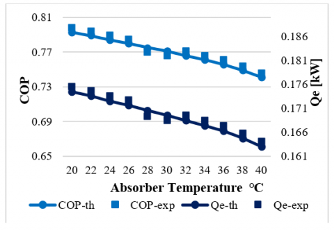
Figure 5. The effect of changing the absorber temperature on the COP and the Qe at Te=2℃, Tc=45.8℃, and Tg=100℃
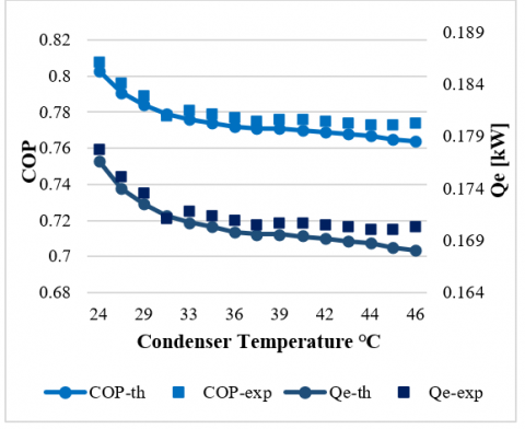
Figure 5 and Figure 6 show the effect of changing the absorber and condenser temperatures on the performance parameters for LiBr-H2O. It is clear that increasing them adversely affects them so the COP and the cooling capacity are reduced when they increase.
Figure 6. The effect of changing the condenser temperature on the COP and the Qe at Te=2℃, Ta=33℃, and Tg=100℃
The experiments were conducted under controlled conditions. Climate variations can influence the system's performance due to changes in ambient temperature and solar radiation availability.
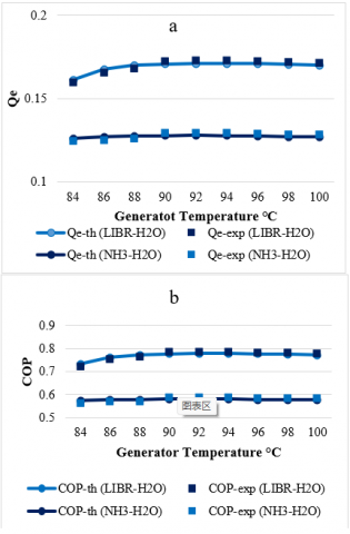
Figure 7. The effect of changing the generator temperature on a) the Qe and b) the COP using Both Pairs at Te=4℃, Ta=33℃, and Tc=45.8℃
4.3 Comparison of NH3-H2O and LiBr-H2O
Figure 7 show the effect of changing the temperature of the generator and evaporator, respectively, on the performance parameters when using different pairs. When comparing NH3-H2O with LiBr-H2O, it turns out that LiBr-H2O performs better and produces a higher cooling capacity by almost 33% compared to NH3-H2O.
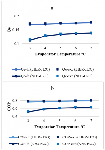
Figure 8 shows that ammonia is more affected than lithium when changing the temperature of the evaporator.
Figure 8. The effect of changing the evaporator temperature on a) the Qe and b) the COP using both pairs at Tg=90℃, Ta=33℃, and Tc=45.8℃
This study investigated the performance of an absorption chiller using both mathematical modeling and experimental validation. The experimental results closely matched the mathematical model, with a maximum deviation of 0.6%. This high level of agreement suggests the validity of both the model and the experimental procedures.
The study compared the performance of two working fluid pairs (LiBr-H2O and NH3-H2O) based on key parameters like COP (Coefficient of Performance) and cooling capacity. The results confirm that operating temperatures significantly influence system performance. Notably, the LiBr-H2O pair demonstrated superior performance, delivering approximately 33% higher cooling capacity compared to NH3-H2O. This advantage is particularly pronounced at high generator temperatures (around 90℃) and low evaporator temperatures (around 6℃).
In essence, the LiBr-H2O absorption chiller system outperforms the NH3-H2O system, particularly under operating conditions with high generator temperatures and low evaporator temperatures. This finding highlights the importance of selecting appropriate working fluids based on the desired operating conditions.
The authors would like to express their thanks to DSR at Al-Zaytoonah University of Jordan for its research fund (Grant No.: 44/17/2022-2023).
|
SHX |
Solution heat exchanger |
|
|
LVHX |
Liquid vapour heat exchanger |
|
|
EES |
Engineering equation solver |
|
|
COP |
Coefficient of performance |
|
| $\dot{\mathrm{m}}$ | Mass flow rate (kg/s) | |
|
$\dot{\mathrm{Q}}$ |
Heat transfer rate (kW) |
|
|
T |
Temperature (℃) |
|
|
$\varepsilon$ |
Effectiveness of heat exchanger |
|
|
Q |
Capacity (kW) |
|
|
$\mu$ |
Dynamic viscosity, kg. m-1 s-1 |
|
|
Subscripts |
||
|
abs |
Absorber |
|
|
con |
Condenser |
|
|
eva |
Evaporator |
|
|
gen |
Generator |
|
|
SS |
Strong solution |
|
|
WS |
Weak solution |
|
|
C,c |
Cooling |
|
|
HP |
Heat pump |
|
|
h |
Enthalpy |
|
|
r |
Refrigerant |
|
|
X |
Solution concentration |
|
[1] Yang, L., Yan, H.Y., Lam, J.C. (2014). Thermal comfort and building energy consumption implications - A review. Applied Energy, 115: 164-173. https://doi.org/10.1016/j.apenergy.2013.10.062
[2] Afonso, C.F.A. (2006). Recent advances in building air conditioning systems. Applied Thermal Engineering, 26(16): 1961-1971. https://doi.org/10.1016/j.applthermaleng.2006.01.016
[3] Elakhdar, M., Tashtoush, B.M., Nehdi, E., Kairouani, L. (2018). Thermodynamic analysis of a novel Ejector Enhanced Vapor Compression Refrigeration (EEVCR) cycle. Energy, 163: 1217-1230. https://doi.org/10.1016/j.energy.2018.09.050
[4] Tashtoush, B.M., Al-Nimr, M.A., Khasawneh, M.A. (2017). Investigation of the use of nano-refrigerants to enhance the performance of an ejector refrigeration system. Applied Energy, 206: 1446-1463. https://doi.org/10.1016/j.apenergy.2017.09.117
[5] Tashtoush, B., Younes, M.B. (2019). Comparative thermodynamic study of refrigerants to select the best environment-friendly refrigerant for use in a solar ejector cooling system. Arabian Journal for Science and Engineering, 44: 1165-1184. https://doi.org/10.1007/s13369-018-3427-4
[6] Kizilkan, O., Khanmohammadi, S., Saadat-Targhi, M. (2019). Solar based CO2 power cycle employing thermoelectric generator and absorption refrigeration: Thermodynamic assessment and multi-objective optimization. Energy Conversion and Management, 200: 112072. https://doi.org/10.1016/j.enconman.2019.112072
[7] Wonchala, J., Hazledine, M., Boulama, K.G. (2014). Solution procedure and performance evaluation for a water-LiBr absorption refrigeration machine. Energy, 65: 272-284. https://doi.org/10.1016/j.energy.2013.11.087
[8] Ma, Y.G., Zhang, X., Liu, M., Yan, J.J., Liu, J.P. (2018). Proposal and assessment of a novel supercritical CO2 Brayton cycle integrated with LiBr absorption chiller for concentrated solar power applications. Energy, 148: 839-854. https://doi.org/10.1016/j.energy.2018.01.155
[9] Ketfi, O., Merzouk, M., Merzouk, N.K., Metenani, S.E. (2015). Performance of a single effect solar absorption cooling system (Libr-H2O). Energy Procedia, 74: 130-138. https://doi.org/10.1016/j.egypro.2015.07.534
[10] Al-Shamani, A.N. (2020). Evaluation of solar-assisted absorption refrigeration cycle by using a multi-ejector. Journal of Thermal Analysis and Calorimetry, 142: 1477-1481. https://doi.org/10.1007/s10973-020-09560-8
[11] Sun, J., Fu, L., Zhang, S.G. (2012). A review of working fluids of absorption cycles. Renewable and Sustainable Energy Reviews, 16(4): 1899-1906. https://doi.org/10.1016/j.rser.2012.01.011
[12] Li, Z.F., Sumathy, K. (2000). Technology development in the solar absorption air-conditioning systems. Renewable and Sustainable Energy Reviews, 4(3): 267-293. https://doi.org/10.1016/S1364-0321(99)00016-7
[13] Shaikh, A., Memon, A.G., Deep, A., Hussain, T. (2017). Thermodynamic analysis of combined vapor compression and vapor absorption refrigeration system. Mehran University Research Journal of Engineering and Technology, 36(3): 733-740. https://doi.org/10.22581/muet1982.1703.27
[14] Carlos, J., Castillo, Á. (2007). Cost estimation of using an absorption refrigeration system with geothermal energy for industrial applications in El Salvador. Geothermal Training Programme.
[15] Lubis, A., Jeong, J., Saito, K., Giannetti, N., Yabase, H., Alhamid, M.I., Nasruddin. (2016). Solar-assisted single-double-effect absorption chiller for use in Asian tropical climates. Renewable Energy, 99: 825-835. https://doi.org/10.1016/j.renene.2016.07.055
[16] Bellos, E., Tzivanidis, C., Antonopoulos, K.A. (2016). Exergetic and energetic comparison of LiCl-H2O and LiBr-H2O working pairs in a solar absorption cooling system. Energy Conversion and Management, 123: 453-461. https://doi.org/10.1016/j.enconman.2016.06.068
[17] Bellos, E., Tzivanidis, C., Antonopoulos, K.A. (2016). Exergetic, energetic and financial evaluation of a solar driven absorption cooling system with various collector types. Applied Thermal Engineering, 102: 749-759. https://doi.org/10.1016/j.applthermaleng.2016.04.032
[18] Bellos, E., Tzivanidis, C., Symeou, C., Antonopoulos, K.A. (2017). Energetic, exergetic and financial evaluation of a solar driven absorption chiller – A dynamic approach. Energy Conversion and Management, 137: 34-48. https://doi.org/10.1016/j.enconman.2017.01.041
[19] Yadav M., Saikhedkar, D.N.K. (2017). Simulation modeling for the performance of vapor absorption refrigeration system using evacuated tube collector and parabolic disc collector working in conjugate systemm. International Research Journal of Engineering and Technology (IRJET), 4(4).
[20] Makahleh, F.M., Badran, A.A., Attar, H., Amer, A., Al-Maaitah, A.A. (2022). Modeling and simulation of a two-stage air-cooled adsorption chiller with heat recovery part I: Physical and mathematical performance model. Applied Sciences, 12(13): 6542. https://doi.org/10.3390/app12136542
[21] Younes, M.B., Altork, Y., Shaban, N.A. (2024). Performance evaluation of a small scale ammonia-water absorption cooling system for off-grid rural homes: A numerical and experimental study. International Journal of Heat and Technology, 42(1): 90-100. https://doi.org/10.18280/ijht.420110