Zhenhua Qu
© 2021 IIETA. This article is published by IIETA and is licensed under the CC BY 4.0 license (http://creativecommons.org/licenses/by/4.0/).
OPEN ACCESS
The drying and heating system (DHS) is the core component of automatic stirring equipment, so analyzing its thermodynamics is crucial for improving the efficiency of the equipment. However, existing empirical thermodynamic formulas generally take certain working conditions as prerequisites, and substituting relevant parameters of DHS into calculation can cause large errors. In view of this problem, this paper attempts to perform thermodynamic analysis and calculation on the DHS of automatic stirring equipment. At first, the material ratio of the automatic stirring equipment was analyzed in the text, and the drying and heating process of mixture was divided into three stages: mixture preheating, mixture drying, and heating mixture to the working temperature. Then, the heat consumption of DHS, the heat consumption of fuel combustion, the consumption rate of the fuel, and the heat efficiency of DHS were measured and calculated. At last, the thermodynamic analysis results of DHS of automatic stirring equipment were given, and the measurement and calculation methods adopted in the paper were proved to be effective.
drying and heating system (DHS), automatic stirring equipment, thermodynamic analysis
Automatic stirring equipment is a kind of important machinery in building construction projects, and its power and fuel consumption take the largest proportion in the total energy consumption of all kinds of building construction equipment [1-5]. The installed power of automatic stirring equipment with an annual mixture output of 200,000 tons can reach more than 820 kW, and it will consume at least 5 million kWh of electricity every year. At present, more than 20,000 automatic stirring equipment of different types have been put on stream in China [6-11]. In this context, how to effectively reduce the power consumption of automatic stirring equipment is an issue requiring the attention from the construction machinery industry [12-15]. The function of DHS is to heat and dry the cold materials, it is the core component of automatic stirring equipment, and analyzing its thermodynamics is a necessity for improving the heating and drying efficiency of the drying drum and reducing its energy consumption; it is the key to increase the efficiency of the automatic stirring equipment [16-23].
Ruby and Sutrisno [24] firstly discussed the problems of how to establish and solve heat equation models, then, it built a heat equation model for rice dryer, and employed the variable separation method to solve it; and the simulation and experiment were conducted under both steady and unsteady state conditions. Souza et al. [25] analyzed a developed non-traditional rotary dryer and used a two-phase model and a set of constitutive equations to describe the drying process, the equations were numerically solved using normal configuration technique, experiment proved that the simulation results were in good agreement with the experimental data. Novak et al. [26] studied the motion of fabrics in the drum of household heat pump drum-type dryer and its influence on the performance parameters of the dryer under different load masses and drum speeds; then multiple regression analysis was performed and a condensate water mass flow model was constructed, as a function of drum speed, load mass, and drying stage, its results can optimize the operating parameters of the dryer, including energy efficiency, drying time for per kilogram of fabric, and condensate water mass flow. For the drying cylinder in the dryer section of paper machine, in order to get a cross-sectional shape of channels with better drainage and heat transfer performance, Dong et al. [27] selected channels with two different cross-sectional shapes to study the steam flow and heat transfer in the channels and compare the changes in heat transfer coefficient of the channels under different working conditions, and the results showed that the heat transfer effect of U-shaped channels in the multi-channel dryer was better than that of other channels. Kumar et al. [28] analyzed the thermodynamics of natural convection dryers made of heat storage materials with and without sensible heat, aiming to take pebbles as sensible heat storage medium to improve the performance of the dryer, the paper also gave energy and exergy analysis to investigate the loss size of pebbles and whether they are suitable for acting as the sensible heat storage material. Singh et al. [29] used 3D computational fluid dynamics simulation to study the gas-solid fluidization behavior and heat transfer characteristics in a non-slit rotating solid bed; in ANSYS FLUENT 14.5, numerical simulation was carried out based on the Euler-Eulerian method, and the experimental results showed that, main factors affecting the volume of reactor include air inlet velocity, inlet pressure, temperature, and heat transfer coefficient; after comparing the numerical calculation results with experimental results, it is found that the maximum error of temperature was 6.98%.
Compared with foreign countries, the domestic drying and heating technology still lags behind. After reviewing the studies of some scholars concerning DHS, it’s found that the existing empirical thermodynamic formulas generally take certain working conditions as prerequisites, and substituting relevant parameters of DHS into calculation can cause large errors, so we need more accurate numerical simulation methods to analyze the working process of DHS and study the changes in its heat efficiency and energy consumption. For this reason, this paper performed thermodynamic analysis and calculation on the DHS of automatic stirring equipment. The second part of the paper analyzed the material ratio of the automatic stirring equipment. The third part divided the drying and heating process of mixture into three stages of mixture preheating, mixture drying, and heating mixture to the working temperature; and measured and calculated the energy consumption of the DHS. The fourth and fifth parts calculated the heat consumption of fuel combustion, the consumption rate of the fuel, and the heat efficiency of DHS. The last part gave the thermodynamic analysis results of the DHS of automatic stirring equipment, and verified the effectiveness of the proposed measurement and calculation methods.
Most automatic stirring equipment adopts a counter-current heating method to heat materials, that is, to install the DHS at the discharge end of the stirring drum to make the materials fully contact with the hot gas. Problems that can be solved by the thermodynamic analysis of the DHS of automatic stirring equipment include: the amount of heat required for drying and heating, the temperature of hot gas at different positions of the drying drum, the consumption rate of the fuel, the heat efficiency of DHS, and the structural parameters of DHS.
The ratio of materials to be stirred and dried can be determined based on the material output rate and type of the automatic stirring equipment, including the mass of materials before stirring and drying, and the water loss after drying. Assuming: Hn represents the production rate of dry materials, namely the amount of dry materials output by the DHS per hour; H0 represents the productivity of the stirring equipment; wg and wy respectively represent the mass of two kinds of materials in the mixture to be stirred; lτ represents the time utilization rate, then there is:
${{H}_{n}}=\frac{1000{{H}_{0}}}{{{l}_{\tau }}}\cdot \frac{100-{{w}_{g}}-{{w}_{y}}}{100}$ (1)
Assuming: Q represents the water content of materials to be stirred and dried, after drying and heating, the materials are completely dehydrated, and Hq, the water loss of the materials within per unit time, can be calculated by Formula 2:
${{H}_{q}}={{H}_{n}}\cdot \frac{Q}{100-Q}$ (2)
According to this, the amount of wet material H input into the stirring equipment within per unit time can be calculated by Formula 3:
$H={{H}_{n}}+{{H}_{q}}=\frac{100{{H}_{n}}}{100-Q}$ (3)
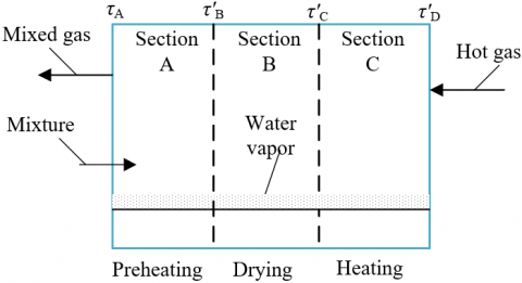
Figure 1. Division of different processing sections of drying drum
The drying and heating process of stirred mixture can be divided into three stages: mixture preheating, mixture drying, and heating mixture to the working temperature, and the three stages respectively correspond to the three processing sections A, B, and C of the drying drum. Section A is for preheating the materials to be stirred, it is located on the side close to the outlet of hot gas and water vapor. Section B is for drying the mixture, it is located in the middle part of the drying drum. Section C is for heating the mixture to the working temperature, and it is located at the side of the hot gas inlet. Figure 1 shows the division of the different processing sections of the drying drum.
The hot gas used for heating the mixture enters Section A from Section C, then the residual heat, plus the water vapor generated in Section B, can be used to preheat the cold mixture that has just entered Section A. The heat consumed by preheating includes two parts: the heat consumed by preheating the mixture, and the heat consumed by preheating the water contained in the mixture. Assuming: W'A represents the total amount of heat consumed by preheating the stirred cold mixture per unit time, W''A represents the amount of heat absorbed by the preheating of water within per unit time, Dn represents the specific heat of the mixture, Dq represents the specific heat of water, τ1 represents the temperature when the materials are just fed, τ2 represents the temperature when the water is strongly evaporated, then Formula 4 gives the formula for calculating the heat consumed by preheating the mixture:
$W_{A}^{'}={{D}_{n}}{{H}_{n}}\left( {{\tau }_{2}}-{{\tau }_{1}} \right)$ (4)
Formula 5 gives the formula for calculating the heat consumed by preheating the water contained in the mixture:
$W_{A}^{''}={{D}_{q}}{{H}_{q}}\left( {{\tau }_{2}}-{{\tau }_{1}} \right)$ (5)
Therefore, the heat consumption of the stirred mixture in Section A is:
${{W}_{A}}=W_{A}^{'}+W_{A}^{''}$ (6)
The heat consumption of preheated mixture in Section B contains two parts: the heat consumed by evaporating the water contained in the mixture, and the heat consumed for heating the water vapor to the temperature of output hot gas. Assuming: W'B represents the amount of heat consumed by evaporating the water contained in the mixture within per unit time, W''B represents the amount of heat for heating the water vapor to the temperature of wasted gas, ζ represents the latent heat for forming water vapor, Du represents the specific heat of water vapor, τA represents the temperature of hot gas output from the drying drum, then the amount of heat consumed by evaporating the water in the mixture can be calculated by Formula 7:
$W_{B}^{'}={{H}_{q}}\zeta $ (7)
The heat consumed for heating water vapor to the temperature of output hot gas can be calculated by Formula 8:
$W_{B}^{''}={{D}_{u}}{{H}_{q}}\left( {{\tau }_{a}}-{{\tau }_{2}} \right)$ (8)
Therefore, the total heat consumption of mixture in Section B is:
${{W}_{B}}=W_{B}^{'}+W_{B}^{''}$ (9)
The mixture heated to the working temperature is output from Section C, assuming τ3 represents the temperature when the materials are discharged, then the heat consumption of mixture in Section C can be calculated by Formula 10:
${{W}_{C}}={{D}_{n}}{{H}_{n}}\left( {{\tau }_{3}}-{{\tau }_{2}} \right)$ (10)
To sum up, the effective total heat required by the DHS of the automatic stirring equipment can be calculated by Formula 11:
${{W}_{TOTAL}}={{W}_{A}}+{{W}_{B}}+{{Q}_{C}}$ (11)
Assuming: WHR represents the total amount of heat supplied to the drying drum during fuel combustion, τ'D represents the fuel combustion temperature, when the hot gas produced by fuel combustion exchanges heat with the cold mixture, the amount of heat released for per 1°C temperature drop of the hot gas can be calculated by Formula 12:
${{w}_{0}}=\frac{{{W}_{HR}}}{\tau _{D}^{'}-{{\tau }_{A}}}$ (12)
In the process of drying and heating the mixture, the heat consumption of mixture heating, and the heat loss of the drying drum wall are the main factors for the changes in the heat of hot gas. Assuming τ'C represents the hot gas temperature of Section C, then the value of temperature drop of the hot gas can be calculated by Formula 13:
$\Delta {{\tau }_{C}}=\frac{{{W}_{C}}+{{W}_{HL}}}{{{w}_{0}}}$ (13)
$\tau _{C}^{'}=\tau _{D}^{'}-\Delta {{\tau }_{C}}$ (14)
Assuming: τ'3 represents the hot gas temperature in Section B when the water contained in the mixture starts to evaporate, then the following heat balance equations can be constructed:
${{w}_{0}}\left( \tau _{C}^{'}-\tau _{B}^{'} \right)=W_{B}^{'}+{{D}_{u}}{{H}_{w}}\left( \tau _{B}^{'}-\tau _{B}^{{}} \right)$ (15)
$\tau _{B}^{'}=\frac{{{w}_{0}}\tau _{C}^{'}+{{D}_{u}}{{H}_{q}}-W_{B}^{'}}{{{w}_{0}}+{{D}_{u}}{{H}_{q}}}$ (16)
At last, τA, the temperature of mixed gas containing hot gas and water vapor discharged from Section A was calculated from the perspective of heat balance, then there is:
${{w}_{0}}\left( \tau _{2}^{'}-{{\tau }_{a}} \right)+{{D}_{u}}{{H}_{q}}\left( \tau _{2}^{'}-{{\tau }_{a}} \right)={{W}_{\tau }}$ (17)
Combining with Formula 13, we can get:
${{\tau }_{a}}=\frac{\left( {{w}_{0}}+{{D}_{u}}{{H}_{q}} \right)\tau _{2}^{'}-{{W}_{1}}}{{{w}_{0}}+{{D}_{u}}{{H}_{q}}}$ (18)
After fuel combustion, the heated hot gas passes through the three processing sections C, B, and A one by one, and passes its own heat to the mixture, and the temperature of the hot gas drops from τ'D to τA. Assuming: w represents the heat transferred by the hot gas to the mixture, w1 is the heat contained by hot gas when per unit mass of fuel is burnt to heat the hot gas to temperature τ'D; assuming: Dn1 represents the average specific heat of the hot gas with a temperature of τD, Dn2 represents the average specific heat of the hot gas with a temperature of τA, then there is:
${{w}_{1}}={{D}_{n\text{1}}}\tau _{D}^{'}$ (19)
The heat contained by the hot gas when per unit mass of fuel is burnt to heat the hot gas to a temperature of τA can be calculated by Formula 20:
${{w}_{2}}={{D}_{n\text{2}}}\tau _{A}^{'}$ (20)
Combining Formulas 19 and 20, the amount of heat transferred from the hot gas to the mixture can be calculated as:
$w={{w}_{1}}-{{w}_{2}}$ (21)
Assuming: Σn represents the mass of hot gas produced by the combustion of per unit mass of fuel, then the effective heat utilization Fu can be calculated by Formula 22:
${{F}_{u}}=w\sum{n}$ (22)
Assuming: Wu represents the heat required for the drying drum to run for per unit time, then the fuel consumption rate nτ of the drying drum can be calculated by Formula 23:
${{n}_{\tau }}=\frac{{{W}_{u}}}{{{F}_{u}}}$ (23)
Assuming: RU1 represents the enthalpy value of per unit weight of water vapor when the temperature is RU1, RU2 represents the enthalpy value of 1 kg of water, then the heat contained by the mixed gas containing hot gas and water vapor discharged from the drying drum can be calculated by Formula 24:
${{W}_{D}}={{n}_{\tau }}\left[ \sum{n{{D}_{{{n}_{2}}}}\left( {{\tau }_{A}}-{{\tau }_{x}} \right)+{{n}_{2}}\left( R{{U}_{1}}-R{{U}_{2}} \right)} \right]$ (24)
According to the law of energy conservation, the heat generated by fuel combustion satisfies equation Wl=Fk+ngDgτg + nxDxτx, then the total heat consumption of per unit time satisfies equation W=Wl×nτ; the effective utilization rate of heat of Section A can be calculated by Formula 25:
${{w}_{A}}=\frac{{{W}_{A}}+{{D}_{u}}{{D}_{q}}\left( \tau _{B}^{'}-{{\tau }_{A}} \right)}{W}\times 100%$ (25)
The effective utilization rate of heat of Section B can be calculated by Formula 26:
${{w}_{B}}=\frac{{{W}_{B}}+{{D}_{u}}{{D}_{q}}\left( \tau _{B}^{'}-{{\tau }_{B}} \right)}{W}\times 100%$ (26)
The effective utilization rate of heat of Section C can be calculated by Formula 27:
${{w}_{C}}=\frac{{{W}_{C}}}{W}\times 100%$ (27)
The heat loss rate of the drying drum wall can be calculated by Formula 28:
${{w}_{HL}}=\frac{{{W}_{HL}}}{W}\times 100%$ (28)
The heat loss rate of mixed gas containing discharged hot gas and water vapor can be calculated by Formula 29:
${{w}_{A}}=\frac{{{W}_{A}}}{W}\times 100%$ (29)
In summary, the heat efficiency Ω of DHS of the automatic stirring equipment is the sum of the effective heat consumption of each processing section, namely:
$\Omega ={{w}_{A}}+{{w}_{B}}+{{w}_{C}}$ (30)
With the DHS of asphalt mixture stirring equipment as an example, this paper performed simulation and experiment, and Table 1 gives the material ratio of asphalt concrete mixture. Due to the large amount of experimental data, in the analysis process of simulation and experiment, only a certain and limited amount of machine unit data of each processing stage of the mixture had been adopted for analysis.
Table 2 gives the experimental data of drying characteristics, and the drying time lasted 0-30 min. According to the data in Table 2, the characteristic curve of asphalt mixture sample was plotted as shown in Figure 2.
Table 1. Material ratio of asphalt concrete mixture
|
Component |
Asphalt |
Stone powder |
Gravel |
Sand |
Total |
|
|
Coarse-grained aggregate |
Mineral aggregate |
6 |
3 |
66 |
38 |
113 |
|
Product aggregate |
4.7 |
2.54 |
61 |
36 |
104.24 |
|
|
Medium-grained aggregate |
Mineral aggregate |
7 |
9 |
44 |
49 |
109 |
|
Product aggregate |
5.8 |
7.8 |
40 |
45 |
98.6 |
|
|
Fine-grained aggregate |
Mineral aggregate |
6.4 |
9 |
41 |
45 |
101.4 |
|
Product aggregate |
6.2 |
8.4 |
40 |
42 |
96.6 |
|
Table 2. Experimental data of drying characteristics
|
Drying time |
3 |
6 |
9 |
12 |
15 |
|
Water content |
0.26584 |
0.23168 |
0.16295 |
0.08451 |
0.04958 |
|
Water loss rate |
1.85 |
5.74 |
12.14 |
19.52 |
20.74 |
|
Water content change rate |
-0.02157 |
-0.02536 |
-0.03152 |
-0.04135 |
-0.02157 |
|
Drying rate |
0.14525 |
0.18546 |
0.17485 |
0.13269 |
0.14285 |
|
Drying time |
18 |
21 |
24 |
27 |
27 |
|
Water content |
0.05195 |
0.02873 |
0.00358 |
0.00147 |
0.00087 |
|
Water loss rate |
21.62 |
24.15 |
23.75 |
27.42 |
29.11 |
|
Water content change rate |
-0.01274 |
-0.02158 |
-0.03162 |
-0.04157 |
-0.04784 |
|
Drying rate |
0.16259 |
0.17485 |
0.19548 |
0.16257 |
0.1421 |
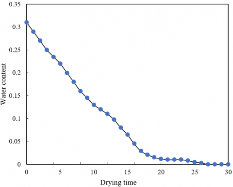
Figure 2 shows the change in water loss of asphalt mixture sample with drying time, and Figure 3 shows the change in water content of asphalt mixture sample with drying time. The change trends of water loss and water content of the asphalt mixture sample with the progress of the drying and heating process could be known from Figure 2 and Figure 3. In terms of the water loss of asphalt mixture sample, as the drying and heating process continues, the moisture inside the sample is largely vaporized, resulting in an upward trend in the water loss, and the longer the drying and heating time, the greater the water loss. In terms of the water content of asphalt mixture sample, as the drying and heating process continues, the water content shows an approximate linear decline in the initial stage; then, when it reaches the final stage of drying and heating, the change of water content of the sample tends to become stable, and reaches 0 in the end.
Figure 2. The change of water loss of mixture over drying time
Figure 3. The change of water content of mixture over drying time
Figure 4 gives the curve of the drying rate of asphalt mixture sample. The asphalt mixture samples used in the experiment were made of tiny solid materials with different particle sizes. According to Figure 4, after the drying and heating experiment starts, the drying rate of asphalt mixture sample is around 0.145 kg/m2∙min all the time, the change is relatively stable.
At the beginning of the experiment, the heat absorbed by asphalt mixture sample was mainly used for evaporating the water adsorbed on the surface of the sample and for increasing its own temperature, so in this stage, the drying rate of the sample briefly showed a fluctuating and rising trend. The constant-rate drying stage of the asphalt mixture sample was relatively long, it’s because as the drying and heating process continues, there’re water content differences both inside and on surface of the sample, under the effect of such difference, the water inside the asphalt mixture gradually diffuses to the surface.
During this process, if the external hot gas flow applied to the asphalt mixture sample is maintained at a constant flow rate, and the fuel supply temperature is constant as well, then the evaporation rate of the asphalt mixture sample would remain unchanged.
Judging from the drying and heating process of the asphalt mixture sample, it can be seen that the mixture requires a long time changing from the initial state to the completed dried state, this indicates that it’s difficult for the asphalt mixture to realize full dehydration within a fixed time interval in the DHS of the automatic stirring equipment. In specific engineering applications, we only need to control the rotate speed of the drying drum and the input amount of mixture to realize an ideal balance between the water absorption amount and the water dehydration amount of the mixture, in this way, continuous drying of the asphalt mixture could be achieved.
Figure 5 shows the temperature of mixture under different hot gas supply modes. Under the two modes, the change trends of sample temperature were basically the same, and both increased with the extending of drying and heating time. According to the figure, since the drying area of the centrifugal air flow supply mode was greater than of the axial air flow supply mode, the mixture temperature of the centrifugal air flow supply mode was always higher than that of the axial air flow supply mode, and the maximum temperature difference reached 4°C.
Figure 4. Change of drying rate with water content of mixture sample
Figure 5. Temperature of mixture under different hot gas supply modes
Figure 6. Mixture temperature at a fixed height under different hot gas supply modes
Figure 6 shows the mixture temperature at a fixed height of the drying drum with dual air inlets under different hot gas supply modes, and the fixed height was 3.5 m. After performing axial symmetry processing with the central axis of the drying drum as the axis, it can be discovered that the mixture temperatures under both modes increased first and decreased later, the hot gas temperatures at the two air inlets were the highest, the heat transferred to mixture was the most, so the mixture temperatures were the highest at these positions. At the same time, it can be clearly seen that the mixture temperature of the centrifugal air flow supply mode was higher than that of the axial air flow supply mode, and the maximum temperature difference was 14°C, which had proved that, under the condition that air inlets had been added to the drying drum, the drying and heating of the mixture under the centrifugal air flow supply mode was also better than that under the axial air flow supply mode.
This paper conducted thermodynamic analysis and calculation on the DHS of automatic stirring equipment. At first, the material ratio of the automatic stirring equipment was analyzed; then the drying and heating process was divided into three stages: mixture preheating, mixture drying, and heating mixture to the working temperature; after that, the heat consumption of DHS, the heat consumption of fuel combustion, the consumption rate of the fuel, and the heat efficiency of DHS were measured and calculated.
This paper took the DHS of asphalt mixture stirring equipment as the example to conduct simulation and experiment, gave the experimental data of the drying characteristics of asphalt mixture, plotted the curves of water loss and water content of asphalt mixture with the progress of the drying and heating process, and studied the change laws of the drying rate of asphalt mixture with the accumulation of drying and heating time. Moreover, the paper also proposed effective suggestion of controlling the rotate speed of drying drum and the input amount of mixture. At last, the paper gave the curves of mixture temperature under different hot gas supply modes, and the curves of mixture temperature at a fixed height of the drying drum under different hot gas supply modes, and verified the advantages of the centrifugal air flow supply mode in energy conservation.
[1] Liu, H. (2021). Experimental research on the mixing performance of follow-up dynamic mixing equipment. Journal of Physics: Conference Series, 1965(1): 012118. https://doi.org/10.1088/1742-6596/1965/1/012118
[2] Liu, H., Jia, J., Liu, N., Hu, X., Zhou, X. (2018). Effect of material feed rate on sieving performance of vibrating screen for batch mixing equipment. Powder Technology, 338: 898-904. https://doi.org/10.1016/j.powtec.2018.07.046
[3] Klykov, M.V., Alushkina, T.V. (2020). Modeling of liquid distribution and mixing in mass-transfer equipment columns having dumped packings. Chemical and Petroleum Engineering, 55(9): 775-784. https://doi.org/10.1007/s10556-020-00693-z
[4] Ma, D.C., Liu, K. (2020). Modeling and simulation of mixing uniformity of double drum regenerative mixing equipment. Journal of Huazhong University of Science and Technology (Natural Science Edition), 48(3): 7-11, 17. http://dx.chinadoi.cn/10.13245/j.hust.200302
[5] Rogova, O.V., Neyman, V.Y. (2019). Electromagnetic motor for technological vibratory mixing equipment. 2019 20th International Conference of Young Specialists on Micro/Nanotechnologies and Electron Devices (EDM), Erlagol, Russia, pp. 774-777. https://doi.org/10.1109/EDM.2019.8823372
[6] Smetanin, V., Victor, D., Lytkin, V., Lukonin, D., Dvoeglazov, C. (2021). Induction motors for use in the strong power fields equipment for processing spent nuclear fuel in the special module of the prototype mixing device for an energy complex. 2021 XVIII International Scientific Technical Conference Alternating Current Electric Drives (ACED), Ekaterinburg, Russia, pp. 1-4. https://doi.org/10.1109/ACED50605.2021.9462289
[7] Arakelyan, E.K., Andryushin, A.V., Mezin, S.V., Kosoy, A.A. (2021). Features of the multi-criteria optimization mathematical model of the thermal and electrical loads distribution at a combined heat and power plant with a mixed equipment composition. Journal of Physics: Conference Series, 2090(1): 012012. https://doi.org/10.1088/1742-6596/2090/1/012012
[8] Makarch’yan, V.A., Chernyaev, A.N., Andryushin, A.V., Pechenkin, S.P., Lisitsa, V.I., Logvinov, E.I., Molchanov, A.Y. (2013). A software system used for load distribution at a combined heat and power plant with the complex mix of the equipment and complex schemes of heat and electric power supply. Thermal Engineering, 60(5): 374-380. https://doi.org/10.1134/S0040601513050078
[9] Zhang, D., Gui, W., Wang, W., Yang, C.H. (2010). Mixed dynamic reactive power compensation equipment and its application. Electric Machines and Control, 14(2): 71-79.
[10] Zhu, H., Nienow, A.W., Bujalski, W., Simmons, M.J. (2009). Mixing studies in a model aerated bioreactor equipped with an up-or a down-pumping ‘Elephant Ear’agitator: Power, hold-up and aerated flow field measurements. Chemical Engineering Research and Design, 87(3): 307-317. https://doi.org/10.1016/j.cherd.2008.08.013
[11] Woziwodzki, S., Broniarz, L. (2008). The mixing time of power-law fluids in a vessel equipped with single and dual turbine impellers. Chemical and Process Engineering, 29: 403-424.
[12] Martı́nez, F.J.R., Plasencia, M.A.Á.G., Gómez, E.V., Dı́ez, F.V., Martı́n, R.H. (2003). Design and experimental study of a mixed energy recovery system, heat pipes and indirect evaporative equipment for air conditioning. Energy and Buildings, 35(10): 1021-1030. https://doi.org/10.1016/S0378-7788(03)00056-2
[13] Kostikj, A., Kjosevski, M., Kocarev, L. (2015). Impact of mixed traffic in urban environment with different percentage rates of adaptive stop&go cruise control equipped vehicles on the traffic flow, travel time, energy demand and emission. 2015 IEEE 18th International Conference on Intelligent Transportation Systems, Gran Canaria, Spain, pp. 1601-1608. https://doi.org/10.1109/ITSC.2015.261
[14] Smetanin, V., Victor, D., Lytkin, V., Lukonin, D., Dvoeglazov, C. (2021). Induction motors for use in the strong power fields equipment for processing spent nuclear fuel in the special module of the prototype mixing device for an energy complex. 2021 XVIII International Scientific Technical Conference Alternating Current Electric Drives (ACED), Ekaterinburg, Russia, pp. 1-4. https://doi.org/10.1109/ACED50605.2021.9462289
[15] Zhang, C., Jiao, S., Xie, L., Gu, H. (2017). Modeling and simulation of material curtain density for asphalt mixing plant rotary dryer. Journal of Huazhong University of Science and Technology (Natural Science Edition), 45(5): 55-60. http://dx.doi.org/10.13245/j.hust.170511
[16] Jiang, Q., Zhang, Y., Yan, S., Xu, L. (2021). Optimal design of an angular box for a mixed flow grain dryer. Applied Engineering in Agriculture, 37(4): 555-562. https://doi.org/10.13031/aea.14643
[17] Abubakar, S., Anafi, F.O., Kaisan, M.U., Narayan, S., Umar, S., Umar, U.A. (2020). Comparative analyses of experimental and simulated performance of a mixed-mode solar dryer. Proceedings of the Institution of Mechanical Engineers, Part C: Journal of Mechanical Engineering Science, 234(7): 1393-1402. https://doi.org/10.1177%2F0954406219893394
[18] Jayaram, P., Bhattu, N.R., Jayaraman, J., Nagappan, B., Subramaniam, L.S. (2020). Experimental investigation on the treatment of mixed market waste by a novel rotary air dryer. Waste and Biomass Valorization, 11(5): 2153-2162. https://doi.org/10.1007/s12649-018-0516-2
[19] Ekka, J.P., Palanisamy, M. (2020). Determination of heat transfer coefficients and drying kinetics of red chilli dried in a forced convection mixed mode solar dryer. Thermal Science and Engineering Progress, 19: 100607. https://doi.org/10.1016/j.tsep.2020.100607
[20] Lakshmi, D.V.N., Muthukumar, P., Layek, A., Nayak, P.K. (2019). Performance analyses of mixed mode forced convection solar dryer for drying of stevia leaves. Solar Energy, 188: 507-518. https://doi.org/10.1016/j.solener.2019.06.009
[21] Ayua, E., Mugalavai, V., Simon, J., Weller, S., Obura, P., Nyabinda, N. (2017). Comparison of a mixed modes solar dryer to a direct mode solar dryer for African indigenous vegetable and chili processing. Journal of Food Processing and Preservation, 41(6): e13216. https://doi.org/10.1111/jfpp.13216
[22] Tiwari, S., Tiwari, G.N. (2017). Energy and exergy analysis of a mixed-mode greenhouse-type solar dryer, integrated with partially covered N-PVT air collector. Energy, 128: 183-195. https://doi.org/10.1016/j.energy.2017.04.022
[23] Tiwari, S., Tiwari, G.N. (2016). Exergoeconomic analysis of photovoltaic-thermal (PVT) mixed mode greenhouse solar dryer. Energy, 114: 155-164. https://doi.org/10.1016/j.energy.2016.07.132
[24] Ruby, T., Sutrisno, A. (2021). Mathematical modeling of heat transper in agricultural drying machine room (box dryer). Journal of Physics: Conference Series, 1751(1): 012029. https://doi.org/10.1088/1742-6596/1751/1/012029
[25] Souza, G.F.M.V., Avendaño, P.S., Francisquetti, M.C. C., Ferreira, F.R.C., Duarte, C.R., Barrozo, M.A.S. (2021). Modeling of heat and mass transfer in a non-conventional rotary dryer. Applied Thermal Engineering, 182: 116118. https://doi.org/10.1016/j.applthermaleng.2020.116118
[26] Novak, L., Širok, B., Hočevar, M., Gatarić, P. (2021). Influence of load mass and drum speed on fabric motion and performance of a heat pump tumble dryer. Drying Technology, 39(7): 950-964. https://doi.org/10.1080/07373937.2020.1734608
[27] Dong, Y., Dong, J., Qiao, L. (2021). Research on flow and condensation heat transfer coefficient of multi-channel cylinder dryer in u-shaped section. Journal of Physics: Conference Series, 1948(1): 012135. https://doi.org/10.1088/1742-6596/1948/1/012135
[28] Kumar, D., Mahanta, P., Kalita, P. (2020). Energy and exergy analysis of a natural convection dryer with and without sensible heat storage medium. Journal of Energy Storage, 29: 101481. https://doi.org/10.1016/j.est.2020.101481
[29] Singh, P., Mahanta, P., Kalita, P. (2020). Numerical study on the gas-solid hydrodynamics and heat transfer in a rotating fluidized bed with static geometry dryer. International Journal of Heat and Mass Transfer, 153: 119666. https://doi.org/10.1016/j.ijheatmasstransfer.2020.119666