Marco Ottaviani* | Luca Giammichele | Renato Ricci
OPEN ACCESS
The objective of this paper is to explain the design steps and performance analysis of a vertical take-off and landing (VTOL) unmanned air vehicle (UAV) based on a Pilatus B4 glider scale model. Energy consumption, forces and thrust analyses are carry out to determinate the perfect match between low take-off weight and high aerodynamic performance. As a first approach a complete analysis of glider aerodynamic performances are settle to understand and design a proper support for VTOL conversion. Longitudinal static stability is fulfilled by evaluating the center of gravity location with respect to neutral position, nevertheless dynamic stability, and V-n diagram in VTOL configuration are evaluated to guarantee a correct behavior during fixed wing flight mode. In addition, power requirements, motor thrust capability and tilt-motors servo assisted system performance are determinate in perspective of flight performance to find out the perfect transition from multirotor take-off and landing mode to fixed-wing flying state. For these purposes a test bench has being designed to evaluate thrust, electrical absorption and rpm motor behavior along the throttle range. Finally, the assembly and preliminary tests are performed in order to validate the VTOL and Forward flight capability.
vertical take-off and landing (VTOL), tilt-rotor motor glider, fixed wing, mobile laboratory, convertible UAV
The development of Unmanned Aerial Vehicles (UAVs) has attracted enormous interest from the academic community and industry. Although UAVs have originally been known by their military usage, the technological and theoretical advances accomplished in the aerial inspection and robotics, with the cost reduction of electromechanical components, have provided many civilian applications such as search and rescue [1], remote inspection [2], civil transportation [3], public security [4], mapping [5], agriculture [6, 7] to name a few [8].
The most common electric UAV configurations are multi-rotor and fixed-wing aircrafts. Multi-rotor aircrafts have the advantages of hovering flight and Vertical Take-Off and Landing (VTOL) despite having less flight endurance due to a higher power consumption [9, 10]. Otherwise, fixed wing ones provide better range and endurance performances, thus allowing improved energy consumption, but require runways for take-off and landing.
In order to combine the advantages of fixed wing aircrafts and multi-rotors UAVs, a hybrid UAV can be designed and categorized into two main type, convertiplane and tail- sitter [11, 12]. A convertiplane is classified into three subtypes, including tilt-rotor, tilt-wing and dual system. A tail-sitter is able to take-off and land vertically on its tail with the nose and thrust direction pointed upwards, whereas the transition from vertical to horizontal flight and vice-versa are performed by its control surfaces and motors. Tilt-wing system features a wing that is horizontal for conventional forward flight and rotates 90 degrees for vertical take-off and landing. Similar design is used in tilt-motor UAV where only propellers and engine are rotated. A smart design is performed economizing weight and drag surfaces using all motors for both vertical and horizontal flight, whereas in a dual system there are dedicated motors for each flight situation.
Due to its configuration and low construction impact to modify a commercial fixed wing aircraft, we decided to build a tilt-motors capable of take-off, flight and land in every ground configuration [13, 14]. Specifically, a scale glider model has been chosen to being transformed due to his excellent aerodynamic efficiency and the possibility to perform low noise data acquisition mission during motorless flight.
The aim of this study is to incorporate a tilt-rotors system to a semi-acrobatic scale glider model in a way to let him perform a controlled vertical and take-off landing, evaluating structural changes, aerodynamic performance and electronics flight controls.
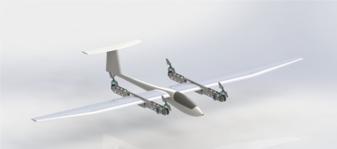
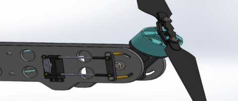
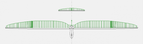
First step of the process is to design a proper layout capable of connecting all motors to the fixed wing structure. The idea is to realize two different frames, one for each wing, where all four motors could be mounted. In particular each frame should sustain two motors, a rear fixed and a front tiltable ones (Figure 1)
A scale glider model named “Pilatus” has been chosen to being modified, due to its strength, easy maneuvers skills, excellent flight and acrobatic performances. Table 1 shows its main characteristics.
Figure 1. VTOL configuration
Table 1. Pilatus characteristics
|
Wing span |
3000 [mm] |
|
Fuselage length Table size |
1320 [mm]can be |
|
Wing area |
56.6 [dm2] |
|
Weight |
2500 [gf] |
|
Airfoil |
HQ2/12 |
|
Controls |
Ailerons, elevators, rudder, airbrakes |
2.1 Motor’s frame design
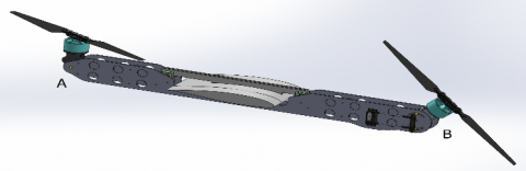
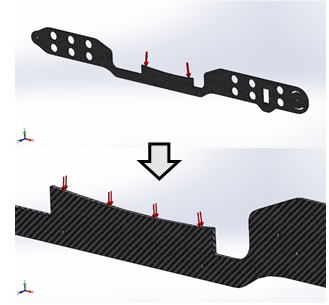
In the adopted solution, each frame is composed by two carbon fiber plates connected together by aluminum blocks to satisfy light weight and strength requirements. Each plate is realized from 3 mm thick carbonfibre material shaped at water high pressure cutting machine.
Each structure provides two connecting spots for the motors: a fixed rear one named (A) where motors plate is mounted forcing lift along vertical direction and a front rotating one, named (B), where propeller-motor coupling is able to tilt according to desired flight configuration (Figure 2).
Figure 2. Motor frame design
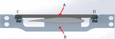
A profiled housing has been realized on each carbon fiber frame to couple the wing airfoil outline so to provide a strength and precise connection frame-wing (Figure 3).
Figure 3. Frame/Wing Coupling system
To avoid undesired wing twist during take-off and landing procedure is crucial that thrust center coincides with center of gravity. Furthermore is important to maintain the structure as light as possible and ensure any interference between motor air flow and wing area. For these reasons, a proper frame dimensions have been chosen (Table 2).
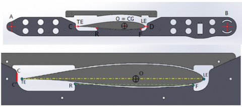
To distribute the pressure force along wing/frame connection and have the possibility to regulate the angle of attack of all system, we decide to design a 140 mm profiled area to couple the HQ2/12. A detailed imagine about the fixing system which let us easily fit and remove the motor frame is shown in Figure 4.
Table 2. Frame dimensions
|
OA = OB |
356.5 [mm] |
|
OR = OFTable size |
70 [mm]can be |
|
OD |
102 [mm] |
|
OC |
152.2 [mm] |
|
Wing chord (LE – TE) |
214.2 [mm] |
|
CG position (LE – CG) |
82 [mm] |
Figure 4. locking system
It consists of two separated components (A & B) connected by solid aluminum blocks. This system allows a rotational movement around a fixed-point C and provides a closing point D in such a way to insert and fix the wing within the carbon frame. As first approach we decide to take the horizontal frame line parallel to the wing chord in a way to obtain a glider leveled hovering flight.
For better understanding forces and displacement behavior, a static load FEM analysis has been carried out using a cad simulator. In particular has been used a linear elastic orthotropic model embedded within the program using Carboresine as material assigned. Carbon characteristics used are listed in Table 3.
Table 3. Carbon fiber characteristics
|
Elastic module - X |
231000 [MPa] |
|
Elastic module - YTable size |
22000 [Mpa]can be |
|
Elastic module - Z |
22000 [Mpa] |
|
Poisson coefficient - XY |
0.3 |
|
Poisson coefficient - YZ |
0.4 |
|
Poisson coefficient - XZ |
0.3 |
|
Tensile strength - X |
44800 [Mpa] |
|
Yield strength |
4150 [Mpa] |
|
Mass density |
1360 [Kg/m3] |
Table 4. Calculated masses
|
VTOL total mass (Mvtol) |
6500 [gf] |
|
Single propulsion module mass (Mprop)Table size |
950 [gf]can be |
|
VTOL propulsion free mass (Mnoprop) |
4600 [gf] |
Firstly, to simulate frame performance, a complete VTOL plane weight of 6500 gf has been supposed considering a Load Capacity ‘LC’ limit of 120 g/dm2 with a wing span of 56.6 dm2. Actually a total real weight of 6350 gf will be measured later.
To evaluate the right pressure which has to be applied along to the connecting area, we had to reduce the estimated total weight force by the engine and propeller masses which are self-sustaining. In Table 4 masses considered are listed.
Each frame is composed by two carbon fiber plates, the calculated pressure (P) applied over all the Contact Area “Ac” (Figure 5) should be:
$M_{\text {plate }}=\frac{M_{\text {noprop }}}{4}=1150[\mathrm{gf}]$ (1)
$F_{\text {plate }}=M_{\text {plate }} \cdot g \cdot X=22563[N]$ (2)
$P=\frac{F_{\text {plate }}}{A_{c}}=53593\left[\mathrm{~N} / \mathrm{m}^{2}\right]$ (3)
Figure 5. FEM simulation Pressure applied
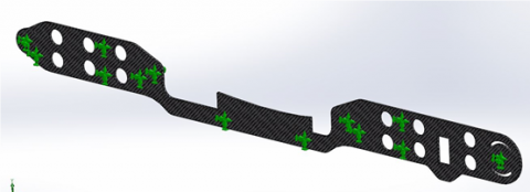
Fixed geometry constrains with cylindrical radial distribution have been applied on all 13 holes where spacers and motor plates connection screws are situated (Figure 6).
Figure 6. Static constrains
The simulation of static load analysis has returned results related to the calculation of stress, displacement and deformation of the plate under the imposed loads. A brief summary is presented below.
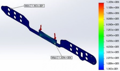
Figure 7. Stress calculation – Von Mises criteria
|
Minimum stress |
0.196303 [N/m2] |
node 27281 |
|
Maximum stress |
1.2091∙106 [N/m2] |
node 409 |
Compared to maximum tensile strength of σmax = 4.480∙109 [N/m2], we can say that it works under large safety margins.
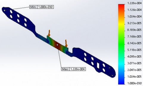
Figure 8. Displacement criteria
|
Minimum displ |
0 [mm] |
node 13 |
|
Maximum displ |
0.0001228 [mm] |
node 14202 |
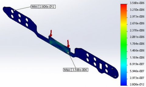
Figure 9. Deformation criteria
|
Minimum def |
2.8058∙10-12 [mm] |
node 12888 |
|
Maximum def |
3.5675∙10-6 [mm] |
node 9892 |
2.2 Motor testing and tilt system design
Considering a load capacity limit of 120 g/dm2, an overall weight of 6500 gf has to be considered to determinate the motors suitable for this application.
Trough eCalc RC calculator, an open source selecting program, an outrunner brushless electric motor powered by 24V direct current with permanents magnets has been chosen.
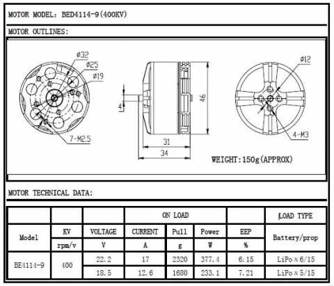
The thrust force of each motor is 2320 gf powered with 22 Volt with an absorbed current of 17 A. Technical data are reported in Figure 10.
Figure 10. Brushless motor data
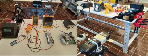
To verify reported data and evaluate the real electrical absorption of engine/prop combination, a motor test bench has been realized (Figure 11). Motor has been powered using a 6S LiPo battery which has a full charge voltage of 25.2 V. Table 5 shows the thrust and electrical absorption from 0 to 100% throttle.
Figure 11. Motor test bench
Table 5. Test bench results
|
Throttle (%) |
Voltage [V] |
Current [A] |
Thrust [N] |
RPM |
|
10 |
0 |
0 |
0 |
0 |
|
20 |
25.2 |
0.5 |
1.06 |
2386 |
|
30 |
25.3 |
1.3 |
3.30 |
3265 |
|
40 |
25.2 |
2.6 |
6.68 |
4176 |
|
50 |
25.2 |
4.9 |
10.55 |
5092 |
|
60 |
25 |
8.4 |
15.14 |
5647 |
|
70 |
24.8 |
13.2 |
20.48 |
6003 |
|
80 |
24.7 |
18.4 |
25.39 |
6429 |
|
90 |
24.6 |
24.8 |
30.48 |
6844 |
|
100 |
24.5 |
27.6 |
32.05 |
8239 |
Several test sessions have been done, resulting in a proportional behavior compared to the battery state of charge. It is important to always flight with a full charged battery. With a 6S battery it is possible to have a stable hovering flight with a 65% of throttle. The knowledge of this parameters will be crucial during transition programming stage.
Front motors tilt system is carried out by a mechanical parallelogram system which transfers the rotary servocontrol movement to a motor support as shown in Figure 12. Engine and props may rotate from horizontal to vertical position by controlling a servo motor capable of 90° rotation.
Figure 12. Motor tilt system
Lightness, simplicity and durability have been the main focus during tilt system design. This solution let us use a Savox Servo model SA-1256TG which weights 64 gf, has a speed of 0.15 sec/60° and has a torque force of 20 Kgcm powered with a direct current of 6 V. It’s a full digital servo motor which allows us to fine control all the parameters during transition such as the progressive inclination of the front motors and the rotation speed during take-off/forward flight switch and vice-versa.
2.3 Avionics components
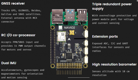
To perform different flight configurations, a controller should be mounted to ensure easy and stable transition between them. A “Navio 2” flight controller, manufactured by Emlid spa, is being chosen due to its excellent performance in fixed wing controlling and his compatibility with Raspberry Pi 3 B+ mini-PC. This is a reliable system where “Ardupilot”, an open-source autopilot program, can easily be installed and used to control all different flight phases (Figure 13).
Figure 13. “Navio 2” flight control
Table 6 shows other electronics components adopted.
Table 6. Electronics components
|
Telemetry module |
Holibro V3 433 Mhz |
|
Radio Control |
Frsky “Horus” with 16 channels |
|
Radio receiver |
Frsky “X8R” |
|
Motor battery |
6S 10000 Mah LiPo |
|
Flight control battery |
7V 1700 Mah NiMH |
|
Servo Battery |
2S 1500 Mah LiPo |
A complete aerodynamics analysis has been done to better understand glider performance at different flight configurations.
3.1 3D glider analysis
As first step in the aerodynamic study of the scale model, a close look at each 2D profile performance, using an analysis tool for airfoils named “XFRL5”, has been carried out.
Pilatus model uses three different airfoils for the main control surfaces. A HQ2012 for the main wing, a NACA 0009 for the tail plane and a NACA 0012 for the rudder. Once all the data are collected within the program, a complete 3D real scale analysis can be performed.
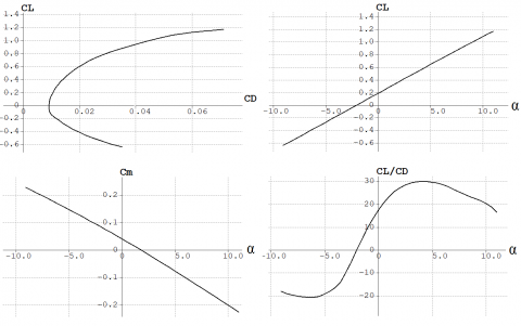
XFRL5 allows different type of examinations. In the present case a constant wind analysis and a fixed lift value have been developed to find out the gliding flight conditions and the aerodynamic characteristics (CL-CD, CL-α, Cm-α, (CL/CD)- α).
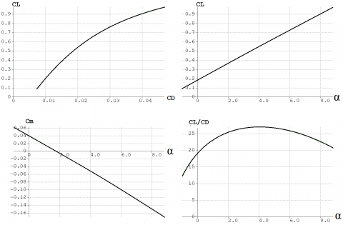
A wind velocity of 25 [m/s] has been chosen in the first analysis while a fixed lift of 6500 gf has been set to perform the second simulation resulting as follow (Figure 14, Figure 15).
Figure 14. Aerodynamic characteristic with V = 25 [m/s]
Figure 15. Aerodynamic characteristic with Lift=6500 [gf]
In the second test there is a narrow range of angle of attack that allows a convergent solution. It can be easily seen that below -1 degree, it is impossible to generate a proper lift to achieve a gliding flight. A max efficiency ‘Emax’ flight configuration is reached with a angle of attack of 5 degrees. A further simulation of the lift distribution at different wind velocity has been done. In particular, flying at Emax, a true air velocity “Vref” of 17.25 m/s is necessary to generate a lift force of 6500 gf (Figure 16).
Figure 16. Lift distribution
3.2 Center of gravity positioning – Static and dynamic stability
The center of gravity position is a crucial parameter that affect glider’s stability. Thus, it is important to evaluate where is originally located and prevent it to move outside the “Static margin” after installing all electronics components previously indicated.
Glider’s manufacturer declares a CG located 82 mm behind the main wing leading edge. We are evaluating it by considering the longitudinal static stability.
The procedure requires the identification of two equivalent rectangular wing surfaces, one for the main and one for the tail wing, with a CMA (medium aerodynamic chord) as chord value. Aerodynamics forces are located into the chord quarter with their relative moments and three specific conditions must been verified:
$C_{m, C G}(\alpha=\alpha \mathrm{eff})=0$ (4)
$C_{m, C G}(\alpha=0)>0$ (5)
$\left[\mathrm{d} C_{m, C G}(\alpha) / \mathrm{d} \alpha\right]<0$ (6)
Being “hn” the coordinate of the most reward position of the CG identifying the indifferent equilibrium status and (hn – h) the static margin, it’s important to have:
$0,05<\left(h_{n}-h\right)<0,20$ (7)
A simple calculation program gives a result of h = 0,07986 m, aligned with manufacturer’s reported data.
To satisfy longitudinal static stability should be also evaluated the tail mounting angle, which should be 1,8 degrees to zeros the equilibrium of all moments. Fortunately, it is already satisfied being the fabric angle status of 2 degrees.
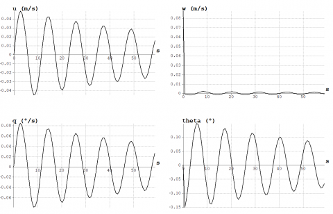
Figure 17 shows the dynamic response of glider stability due to an external disturbance produced by a sudden vertical air flow with a speed of 5 m/s. It can be notice that all parameters, as horizontal speed ‘u’, vertical speed ‘w’, pitch angle ‘theta’ and rotation speed ‘q’, have a decreasing behavior.
Figure 17. Dynamic stability response
3.3 Flight envelope gust and maneuvers in V-n diagram
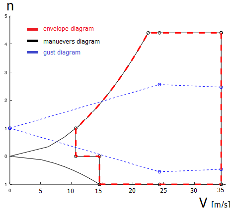
To evaluate which maneuvers and relative speed the chosen motor-glider withstands, an envelope diagram, market in red in Figure 18, has been developed by combining the maneuvers diagram (black line) with the gust one (blue line). In Figure 18, “n” is the load factor equals to lift/weight ratio, and “V” is the wind air velocity. It can be noticed that our motor-glider may resists to a speed flight from 12 to 35 m/s, up to 4,4 as load factor, which are typical values for semi-acrobatic aircraft.
Figure 18. V-n diagram
To understand VTOL behavior, two different layouts must be studied. Vertical take-off in multi rotors quad mode configuration and the transition to forward flight as fixed wing setup.
4.1 Vertical take-off and landing flight phases
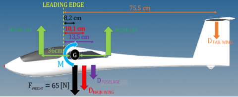
At first phase, our model should takeoff vertically as a multirotor UAV using motor’s lift. Unlike traditional UAV’s, unbalanced forces are generated due to asymmetrical geometry and aerodynamics areas which works as drag flat surfaces. Balance around roll axis has been investigated as bidimensional configuration considering weight and drag forces respectively generated by fuselage, main and tail wings [15] (Figure 19).
Figure 19. Vertical take-off forces
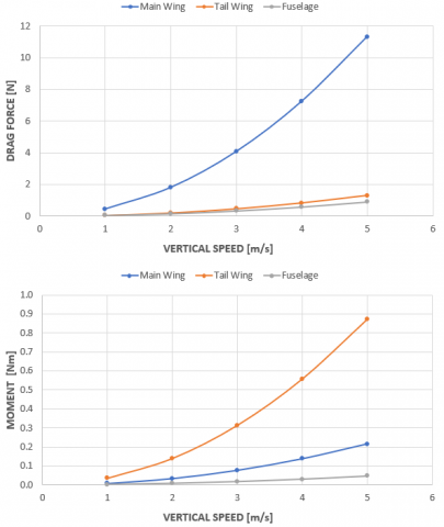
Drag and moment forces are related to vertical speed. From Figure 20 a suitable value is 1.5 [m/s].
It can be notice that tail drag force gives the greatest contribution to unbalance the aircraft during vertical take-off. Therefore, rear motors must create a higher lift than front motors to stabilize the maneuver. At this vertical speed, motor glider will take 45 sec to reach an altitude of 40 m which is the safest minimum quote requested to start transition sequence.
Figure 20. Drag and Moment behaviour
4.2 Transition from multirotor take-off to fixed-wing flying state
Leaning on the electronic stability control provided by the flight controller, the transition sequence starts once a stable hovering flight is reached. During this stage, the relative wind generated by the aircraft motion substantially changes the vehicle dynamic behavior between hovering and cruise flight modes. In helicopter-flight mode (VTOL and hovering), the deflections of aerodynamic surfaces (aileron, rudder, and elevator) do not produce significant dynamical effects, whereas in cruise-flight mode, small deflections produce significant aerodynamic forces. They can be used to generate both the necessary aerodynamic forces to sustain forward flight, and the aerodynamic moments that allow control and guidance. The aircraft stability is demanded to motors during take-off and landing phases, whereas aerodynamics surfaces have the complete attitude control during forward flight time.
Transition between hovering to forward flight basically consist of 3 distinct steps:
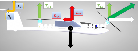
STEP 1
As a stable hovering flight is reached, front motors begin to tilt to generate horizontal thrust. Front motors should perform a higher thrust than the rear motor to achieve a vertical component “T12” equals to “T34” (Figure 21). This ensures a minimum altitude loss and good stability but leads to a higher electric consumption. At this stage all four motors are running under “Navio” controlling.
STEP 2
The higher true air speed is reached, the more increased motor rotation is achieved. The driven digital servo allows us to set up a different degree of rotation compared to measured velocity. In this phase aerodynamics surface begin to generate lift and less motor thrust is demanded to maintain altitude and stability.
STEP3
One a true air velocity of 17.25 m/s “Vref” is reached, front motors move to horizontal position to guarantee forward thrust while rear motors stop spinning. In this phase glider weight is totally hold up by the aerodynamics forces. Fixed wing flight mode is activated and the complete aircraft control is left to the pilot who may use throttle to activate the front motors and gain altitude.
Figure 21. Transition forces
Subsequently to perform a stable vertical landing, a second transition between forward flight to hovering must be considered. At this stage a complete motor rotation from horizontal to vertical position is triggered by a remote control operated by the pilot.
It’s a challenging process where flight controller manages altitude loss, axis rotations and speed reduction until a stable hovering flight is reached. Front motors fully rotate to achieve vertical position and once transition has been completed, all controls are left to the pilot who may perform a vertical landing in multi copter flight mode.
It has been a challenging process to design and assembly a conversion system to allow an aerodynamically performing glider to take-off and landing vertically. Most of the difficulties have been found to incorporate all electronics furniture such as motors, flight controller, batteries, cables etc. in a limited space maintaining weights and aerodynamic characteristics. A complete and thorough analysis has been addressed, evaluating all structural, aerodynamic and electrical aspects reaching a reliable system.
Positive feedback has been observed during indoors first tests where hovering flight capability has been evaluated. Further flights and transition test will be carried out to validate all the considerations made.
The aim of this study is to perfect a VTOL motor-glider in such a way to have the possibility to build a larger and more expensive one which is capable to transport heavy instruments for a long-range monitoring mission.
|
VTOL |
Vertical Take-Off and Landing |
|
UAV |
Unmanned Aerial Vehicle |
|
CG |
Center of Gravity |
|
LC |
Capacity load [g/dm2] |
|
X |
Safety factor = 2 |
|
CL |
Lift coefficient |
|
CD |
Drag coefficient |
|
Cm |
Momentum coefficient |
|
Emax |
Max Efficiency |
|
Vref |
Reference speed |
|
Greek symbols |
|
|
a |
Angle of attack [degree] |
[1] Ryan, A., Hedrick, J.K. (2005). A mode-switching path planner for UAV-assisted search and rescue. In Proceedings of the 44th IEEE Conference on Decision and Control, pp. 1471-1476. https://doi.org/10.1109/CDC.2005.1582366
[2] Metni, N., Hamel, T. (2007). A UAV for bridge inspection: Visual servoing control law with orientation limits. Automation in Construction, 17(1): 3-10. https://doi.org/10.1016/j.autcon.2006.12.010
[3] Rego, B.S., Raffo, G.V. (2016). Suspended load path tracking control based on zonotopic state estimation using a tilt-rotor UAV. In 2016 IEEE 19th International Conference on Intelligent Transportation Systems (ITSC), pp. 1445-1451. https://doi.org/10.1109/ITSC.2016.7795747
[4] Daniel, K., Wietfeld, C. (2011). Using public network infrastructures for UAV remote sensing in civilian security operations. Dortmund Univ (Germany FR).
[5] Lin, Z.J. (2008). UAV for mapping—low altitude photogrammetric survey. International Archives of Photogrammetry and Remote Sensing, Beijing, China, 37: 1183-1186.
[6] Saari, H., Pellikka, I., Pesonen, L., Tuominen, S., Heikkilä, J., Holmlund, C., Antila, T. (2011). Unmanned Aerial Vehicle (UAV) operated spectral camera system for forest and agriculture applications. In Remote Sensing for Agriculture, Ecosystems, and Hydrology XIII, 8174: 81740H. https://doi.org/10.1117/12.897585
[7] Sun, Q., Sun, L., Shu, M.Y., Gu, X.H., Yang, G.J., Zhou, L.F. In: National Engineering Research Center for Information Technology in Agriculture, Beijing, China, ID: 5704154.
[8] Pajares, G. (2015). Overview and current status of remote sensing applications based on unmanned aerial vehicles (UAVs). Photogrammetric Engineering & Remote Sensing, 81(4): 281-330. https://doi.org/10.14358/pers.81.4.281
[9] Gandolfo, D.C., Salinas, L.R., Brandão, A., Toibero, J.M. (2016). Stable path-following control for a quadrotor helicopter considering energy consumption. IEEE Transactions on Control Systems Technology, 25(4): 1423-1430. https://doi.org/10.1109/TCST.2016.2601288
[10] Sumantri, B., Uchiyama, N., Sano, S. (2016). Least square based sliding mode control for a quad-rotor helicopter and energy saving by chattering reduction. Mechanical Systems and Signal Processing, 66: 769-784. https://doi.org/10.1016/j.ymssp.2015.05.013
[11] Saeed, A.S., Younes, A.B., Islam, S., Dias, J., Seneviratne, L., Cai, G. (2015). A review on the platform design, dynamic modeling and control of hybrid UAVs. In 2015 International Conference on Unmanned Aircraft Systems (ICUAS), pp. 806-815. https://doi.org/10.1109/ICUAS.2015.7152365
[12] Yuksek, B., Vuruskan, A., Ozdemir, U., Yukselen, M.A., Inalhan, G. (2016). Transition flight modeling of a fixed-wing VTOL UAV. Journal of Intelligent & Robotic Systems, 84(1): 83-105. https://doi.org/10.1007/s10846-015-0325-9
[13] Maisel, M.D. (2000). The history of the XV-15 tilt rotor research aircraft: from concept to flight (No. 17). National Aeronautics and Space Administration, Office of Policy and Plans, NASA History Division.
[14] Liu, Z., He, Y., Yang, L., Han, J. (2017). Control techniques of tilt rotor unmanned aerial vehicle systems: A review. Chinese Journal of Aeronautics, 30(1): 135-148. https://doi.org/10.1016/j.cja.2016.11.001
[15] Hoerner, S.F. (1965). Fluid-dynamic drag. Hoerner fluid dynamics.