Abdullah Bamoshmoosh | Gianluca Valenti*
OPEN ACCESS
The development of thermal energy storage systems is key to increasing the deployability and reliability of concentrated solar power plants. Previous work from the authors studies the possibility of exploiting vapor-liquid phase change in closed and constant volumes as a thermal energy storage mechanism because of the higher heat transfer coefficients of the phenomenon with respect to solid-liquid phase change energy storage systems. The objective of this paper is to propose a new thermal energy storage condition based on vapor-liquid systems for concentrated solar power plants. The reference case of the Khi Solar One power plant in Upington, South Africa is taken. Results show that increasing the critical temperature of the storage fluid allows for increased temperature differences and higher volume-based energy storage, while the decrease of critical pressure allows lower mechanical stresses on the energy storage system. The use of high critical temperature fluids such as ethylene glycol allows for an increase of the volume-based energy storage of around 95% at same pressure conditions with respect to the base case. The use of low critical pressure siloxanes such as D6 results in a decrease of around 26% in the volume-based energy storage. The use of D6 on the other hand leads to a substantial decrease in the maximum pressure of the storage system, which drops from 8.2 MPa to 1 MPa, allowing the use of cheaper and less complex equipment. Both cases lead to a relevant increase in the maximum storage temperature, increased of 130 K and 55 K respectively.
thermal energy storage, concentrated solar power plants, vapor-liquid equilibria, corresponding state principle
Research in energy storage technologies is of paramount importance for the renewable energy storage infrastructure as well as industry. This is because storage systems allow to accommodate the mismatch between an intermittent energy supply and the varying energy demand [1]. Among others, thermal energy storage technologies show good prospects of becoming an efficient and simple way of storing energy [2].
Latent thermal energy storage is the thermal energy storage mechanism based on the exploitation of phase change phenomena. Wide literature exists on the use of solid-liquid phase change materials in industrial application or for power generation [3-6]. Nevertheless, these materials show some drawbacks to their application, mainly related to the low heat transfer coefficients of the solid-liquid phase change [7].
Previous work from the authors focused on the development and application of the concept of latent thermal energy storage based on the liquid-vapor phase transition in constant and closed volumes [8, 9]. Vapor-liquid phase change shows much higher heat transfer coefficients, although it also shows a decreased mass density of the systems because of the low density of the vapor phase, which impacts the storage capacity.
The goal of this work is to propose an alternative approach to thermal energy storage in concentrated solar power plants based on vapor-liquid thermal energy storage. First, a generalized analysis of the thermodynamic behavior of fluids is developed in order to evaluate the optimal characteristics of the fluid of storage for the selected application. The results of this analysis are used to choose the fluid and assess its storage performances in closed and constant vapor-liquid thermal energy storage systems in the reference concentrated solar power plant. The case of the Khi Solar One power plant in Upington, South Africa is taken as reference.
The following sections provide a presentation of the concepts of vapor-liquid thermal energy storage. Then, a generalized analysis of the fluid storage performances is done in a fluid-independent manner, in order to define the characteristics of the best suited fluids for the storage application. Then, the storage performances of the chosen fluids are shown and compared with the results of the current storage system in the reference solar power plant.
This section presents the principles of vapor-liquid thermal energy storage in closed and constant volumes.
In sensible heat storage systems, the main parameter influencing the volumetric behavior of the liquid phase is temperature through thermal expansion. Dependency of specific volume with pressure is opposite and smaller in magnitude [10]. To keep constant specific volume in a liquid system at increasing temperature, large increases in pressure are required. To avoid pressure surges, expansion vessels are used to accommodate the variation of volume occupied by the storage medium in its operating temperature range.
In two-phase vapor-liquid systems on the other hand, the vapor phase shows the opposite behavior. At increasing temperature, the specific volume of the saturated vapor phase decreases. This is because, unlike the liquid phase volume, the vapor phase specific volume is a strongly decreasing function of pressure and in two-phase systems pressure is an increasing function of temperature. The effect of pressure is more relevant that the effect of temperature for the vapor phase. In two-phase systems, an increase in temperature thus leads to an increase in the specific volume of the liquid phase and to a decrease in the specific volume of the vapor phase.
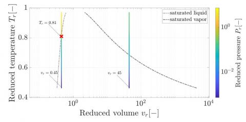
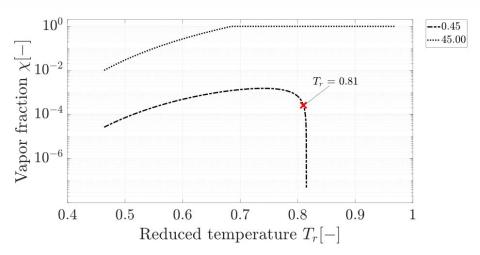
Because of the opposite behavior of the vapor phase and liquid phase volume, the variation of the vapor quality with temperature is not determined a priori in constant-volume processes but rather depends on the boundary conditions of the process itself. In particular, if the system specific volume is above the critical specific volume vc, the expansion of the liquid phase is not able to compensate the contraction of the vapor phase, and eventually the system transitions to a single vapor phase. On the other hand, if the total volume is below vc, at the same temperature and pressure the mass of liquid is larger than in systems with total volume higher than vc. In those systems, the expansion of the liquid fully compensates the contraction of the vapor phase, and the system eventually transitions to a single liquid phase. The transition point from a two-phase system to a single-phase liquid system in constant-volume processes is referred to as countercondensation point and is highlighted in Figure 1. This condition is particularly relevant because at higher temperature the system shows the pressure surges typical of liquid systems with no expansion vessels to accommodate the volume increase. Figure 1 shows two processes for fluids with reduced volumes higher and lower than unity on the reduced volume/reduced temperature plane and the reduced temperature/vapor fraction plane for a generic fluid, calculated with the Corresponding State Principle. The pressure surge at temperatures higher than the countercondensation temperature can be seen, as well as the different behavior of the vapor fraction in the two processes.
Figure 1. Reduced temperature, T_r, as a function of reduced volume, v_r, (above) and vapor fraction, χ, as a function of reduced temperature (below) for systems with total reduced volume below and above 1 for a generalized fluid, with highlight on countercondensation temperature
This section presents the deployment conditions for the storage system. The benchmark architecture of the reference case is shown, as well as the proposed architecture.
3.1 Concentrated solar power plants
Renewable power plants are bound to play a major role in the decarbonization of the energy industry. Among renewable power plants, concentrated solar power plants offer the advantage of allowing the adoption of thermal storage systems instead of electrical storage systems, with significantly cheaper solutions. This allows deployment of more economical technologies to decouple the electrical production from the availability of the solar energy source.
Concentrated power plants are divided into two categories based on their configuration: direct steam generation power plants, where water is used both as heat transfer fluid and as the working fluid, and indirect cycle power plants, where an intermediate heat transfer fluid collects energy from the solar receiver and transfers it to the working fluid in an additional heat exchanger [11]. The first solution allows for the reduction of exergy losses due to heat transfer and for a simpler configuration. On the other hand, although various thermal storage systems have been proposed, based on either latent [12] or sensible heat storage [13], steam accumulators, or Ruth tanks, are the only commercially available solution for direct steam generation plants [14, 15]. In plants with steam accumulators [16], during sunny periods excess steam from the solar collector is stored in pressurized tanks and is discharged during cloudy days or at night. Steam accumulators are a relatively simple solution and have been commercially adopted in a number of concentrated power plants [14, 17, 18].
3.2 Reference case: Khi solar one
The reference case in this work is the storage section of the Khi Solar One Concentrated Solar Power Plant in Upington, South Africa, operated by Abengoa [14, 17, 19]. The Khi Solar One power plant uses steam accumulators as its energy storage system [20]. Excess steam from the evaporator is throttled and stored in pressurized Ruth tanks. High-pressure and base-pressure tanks are used. First, the high-pressure tanks are filled. After the maximum allowed pressure is reached in the high-pressure tanks, the base pressure tanks are filled. When the thermal input to the solar collector decreases, e.g. at night, the saturated steam from the base pressure tanks is superheated by the high pressure steam in a heat exchanger.
Al Kindi et al. [21] performed a rating simulation of the current architecture. The results obtained are summarized in Table 1. In this simulation, the upper and lower boundary of the storage conditions are given by the maximum pressure allowed in the storage tanks and the minimum pressure at which the turbine can safely operate [22]. From this simulation, it is possible to calculate the storage density of the current technology, which is equal to 223 MJ/m3.
3.3 Proposed architectures
In this work, two alternative architectures are proposed, as shown in Figure 2. The power block layout is unchanged in the two configurations. The main difference between the alternative and the current case is the storage system, which is a closed volume in vapor-liquid equilibrium with an internal heat exchanger instead of the steam accumulator. This adds the possibility to bleed the excess steam from the superheater instead of the evaporator. During nominal operating conditions, the steam from the solar tower is bled and condensed in an internal heat exchanger in the two-phase storage tank. When the thermal input to the solar tower decreases, the feedwater is diverted from the solar tower to the hot storage tanks, where it is superheated. The actual conditions of storage in terms of temperature depend strongly on the fluid that is chosen for heat storage and are discussed in the following sections.
Figure 2. Proposed layouts for concentrated solar power plants
The two alternatives differ in the type of accumulators that are implemented. While in the first architecture high-pressure and base-pressure accumulators are used, as in the reference case, in the second architecture only one type of accumulator is used. The first architecture is thus based on the current solution, with a change in the thermal storage system.
This section presents the generalized approach for the selection of the most suited fluid for storage. A parametric analysis of hypothetical fluids in different conditions is shown, and the results of this analysis in reduced form are discussed.
4.1 Rationale
In order to evaluate the optimal fluid for storage, a fluid-independent approach is adopted. A fluid-independent approach allows presenting a generalized analysis of the storage performances by isolating the effect of specific parameters of the fluid themselves. In this work, the Corresponding State Principle in the Lee-Kesler approach is used [23, 24]. This approach allows to isolate the effect of the critical temperature Tc, critical pressure Pc and acentric factor $\omega$. The effect of these parameters is analyzed in a differential manner, evaluating the variation of the heat storage performances at different values of the critical parameters. Once the most suitable critical parameters are found, an effective search for the fluids that are the closest to the best performing conditions can be done. The three effective parameters, Tc, Pc and $\omega$ are thus assumed for the hypothetical fluids that are simulated.
Previous work from the authors [8] shows that the acentric factor $\omega$ has a relevant impact on the thermal storage performances. The higher the acentric factor, the higher the complexity of the fluid and the higher the storage on a volume basis. Since in the Lee-Kesler approach the reference complex fluid is n-octane, with an acentric factor equal to 0.398, in this work an acentric factor $\omega$ of 0.4 is chosen.
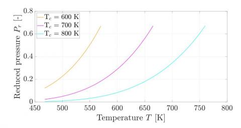
The critical temperatures of the hypothetical fluids are chosen in order to cover the operating range of the current technology in the two-phase region and are thus all higher than 569 K (Table 1). For the parametric analysis, three critical temperatures of 600 K, 700 K and 800 K are chosen. The choice of the critical pressure is not relevant, as reduced pressure can be calculated directly from reduced temperature in the two-phase region. The reduced pressure can be thus analyzed independently from the choice of the critical pressure, making the critical temperature the only variable.
Table 1. Summary of results obtained by Al Kindi et al. [21]
|
Current technology |
|
|
Maximum plant temperature |
800 K |
|
Minimum storage operating temperature |
468 K |
|
Minimum storage operating pressure |
1.4 MPa |
|
Number of base-pressure units |
16 |
|
Maximum base-pressure storage operating pressure |
4.0 MPa |
|
Number of high-pressure units |
3 |
|
Minimum high-pressure storage operating pressure |
3.9 MPa |
|
Maximum high-pressure storage operating pressure |
8.2 MPa |
|
Maximum storage operating temperature |
569 K |
|
Total energy stored |
232 MWh |
|
Total storage volume |
3743 m3 |
|
Storage density |
223 MJ/m3 |
The minimum operating temperature of these systems is assumed to be the same as the minimum temperature of the current layout because of the operability limits on the turbine. The maximum operating temperature needs to be lower than the critical temperature, in order to stay in the two-phase region and avoid countercondensation. A trade-off between maximizing the operating temperature range and minimizing the total specific volume needs to be found, as it is convenient to work at specific volumes lower than the critical volume, as shown in [8]. The maximum operating temperature is thus defined as 95% of the critical temperature, which is a good trade-off between maximizing the temperature range and minimizing the specific volume of the system. The specific volume of each process is thus calculated as the saturated liquid phase at the maximum operating temperature, which thus coincides with the countercondensation temperature.
4.2 Results of the generalized analysis
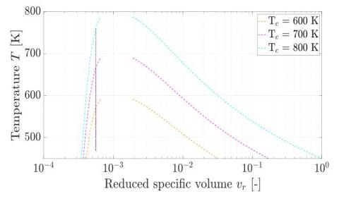
A summary of the inputs is given in Table 2. The three processes, as well as the saturation curves of the three fluids, are represented in Figure 3 in the reduced volume/temperature plane. The reduced volume of the process is the same for the three processes. This is because the reduced temperature at which the volume is calculated is the same for the three processes, and since it is a saturated condition, also the reduced pressure at countercondensation is the same in the three cases. For this reason, the three processes are on the same constant-reduced volume in the reduced volume/temperature plane, where each of the three considered processes ends at its countercondensation temperature.
Table 2. Summary of the process parameters of the three hypothetical fluids
|
|
Fluid 1 |
Fluid 2 |
Fluid 3 |
|
Tc [K] |
600 |
700 |
800 |
|
$\omega$ [-] |
0.4 |
0.4 |
0.4 |
|
Tmax [K] |
570 |
665 |
760 |
|
$T_{r}^{\max }$ [-] |
0.95 |
0.95 |
0.95 |
|
Tmin [-] |
468 |
468 |
468 |
|
$T_{r}^{\min }$ |
0.78 |
0.67 |
0.59 |
|
$v_{r}$ [-] |
6.51e-4 |
6.31e-4 |
6.19e-4 |
Figure 3. Temperature as a function of reduced specific volume and saturation curve for the three fluids with critical temperature equal to 600 K, 700 K, and 800 K
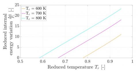
The influence of critical temperature is mainly given by the larger temperature differences that can be reached. Since the reduced volume of the constant-volume process varies very little, the internal energy itself is very slightly affected. The different storage performances are strongly a function of the temperature differences that can be reached. The process for the fluid with the highest critical temperature shows a variation of reduced internal energy on volume basis $\Delta \hat{u} / P_{c}$ that is approximately twice the variation of the fluid with the lowest critical temperature, which is reflected on the temperature differences of the two cases. This is shown in Figure 4.
Figure 4. Reduced volume-based internal energy variation as a function of reduced temperature for the three processes for fluids with critical temperature equal to 600 K, 700 K, and 800 K
Figure 5. Reduced pressure as a function of temperature for the three processes for fluids with critical temperature equal to 600 K, 700 K, and 800 K
The behavior of pressure with respect to temperature can be seen in the temperature/reduced pressure plane in Figure 5. As the critical temperature increases, the reduced pressure at the minimum temperature decreases sharply. Since the maximum reduced temperature is the same, the reduced pressure at the maximum temperature is the same. This leads to a greater variability in terms of pressure for systems with larger temperature differences, as it is expected.
This section shows how the results of the parametric analysis are used to choose the optimal choice of fluids for the concentrated solar power plant thermal storage section. Result of the application of those fluids are then presented.
5.1 Rationale of fluid choice
Results obtained from the parametric study in Section 4 show that:
To apply these principles, two fluids have been chosen. The first fluid is chosen in order to maximize the critical temperature Tc, in order to achieve the highest possible maximum temperature and the highest possible temperature difference. The second fluid is chosen in order to minimize the critical pressure Pc, in order to decrease the variability of pressure in the process and reduce the mechanical stress on the tank. The two fluids that are chosen are ethylene glycol and cyclic siloxane dodecamethylcyclohexasiloxane (D6). The properties of the two fluids are summarized in Table 3.
Table 3. Summary of the properties of the case study fluids
|
|
Ethylene glycol |
D6 |
|
Tc [K] |
719.00 |
645.78 |
|
Pc [MPa] |
10.51 |
0.961 |
Table 3 shows a comparison of the characteristics of the two fluids. Ethylene glycol shows a critical temperature that is around 75 K higher that D6, which results in higher maximum temperatures of storage and larger temperature differences. On the other hand, the critical pressure of D6 is 10% of the critical pressure of ethylene glycol. It is important to note that while for ethylene glycol degradation and thermal instability phenomena are a serious threat at high temperatures [25], numerous works show the stability of various siloxanes such as D6 at temperatures up to 673 K [26-28]. The properties of the two fluids are calculated with REFPROP, ver. 10.0.
5.2 Thermal energy storage performances
5.2.1 Ethylene glycol
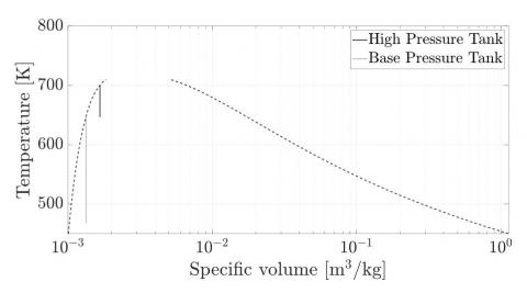
To have a reasonable comparison with the current technology, the first proposed architecture is chosen for ethylene glycol. The same number of high-pressure and base-pressure tanks and the same constraints as in the current architecture in the reference case are used in the proposed architecture. The maximum pressure of the base tank in the proposed case is taken equal to the one from the base case, as well as the minimum and maximum pressures for the high-pressure tanks. The minimum temperature requirement Tmin for the current architecture is considered as the minimum temperature for the base-pressure tank. This allows for direct comparison of the performances of the fluids with the same equipment. The high-pressure tanks and the base-pressure tanks undergo different processes. The processes can be seen on the specific volume/temperature plane in Figure 6.
Figure 6. Temperature as a function of specific volume and saturation curve for ethylene glycol in the base and high-pressure tank
The choice of the specific volume at which to consider the constant-volume process is related for ethylene glycol to the maximum operating pressure. The specific volume of each process is taken as the saturated liquid volume of each process at its maximum temperature. The final temperature of the heating process coincides with the countercondensation temperature of the process itself. Figure 6 shows that, as in the base case, the high-pressure tank fundamentally serves the superheating process, which allows for higher thermal efficiencies in the power section of the cycle [14]. In Figure 7 the volumetric energy storage of each tank is represented.
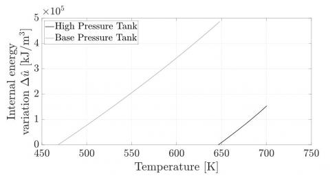
Figure 7. Volume based internal energy variation as a function of specific volume and saturation curve for ethylene glycol in the base and high-pressure tank
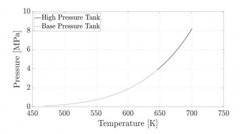
Figure 7 shows that the high-pressure tank, although at higher temperature, has a lower energy storage capacity than the base pressure tank. This is mainly given by two factors: the first is the lower overall specific volume of the system, which results in lower mass, and the second is the lower temperature difference achievable. As in the current architecture, the specific energy stored can be calculated as an average of the storage of the two tanks, weighted on the number of high and base pressure tanks themselves. The calculated total energy storage capacity is around 434 MJ/m3, approximately 95% higher than the base case. This is mainly because of the larger temperature difference that is exploited, both in the base and in the high-pressure tanks. Moreover, the maximum temperature achieved is 130 K higher than in the base case, resulting in higher turbine efficiencies in the discharge process. Figure 8 shows the pressure variation in the two vessels as a function of temperature.
Figure 8. Pressure as a function of temperature for ethylene glycol in the base and high-pressure tank
As can be seen, the pressure variability is approximately the same in the two pressure vessels, as the pressure difference is around 4 MPa for both vessels. Although at lower temperature the base pressure tank would be under vacuum, with a minimum pressure of 0.08 MPa, the structural requirements for the maximum pressure of 4 MPa cover widely the vacuum condition [29]. Degradation and thermal stability phenomena are not considered.
5.2.2 D6
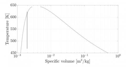
D6 is a cyclic siloxane of which applications are widely investigated as working fluid in the Organic Rankine Cycle field for their good stability, low toxicity, low flammability, and relatively low cost [30-32]. The maximum application temperature of the cyclic siloxanes, such as D6, has been identified to be between 623 K and 673 K [26, 28]. These limits are given mainly because of thermal stability and decomposition. For safety reasons, the maximum temperature allowed is kept on the low side of 623 K. Given the low critical pressure of D6, it is not reasonable to consider the same limits in pressure for base and high-pressure tanks, as unrealistic conditions of supercritical storage would be found. For this reason, a single storage condition has been identified, as in the second proposed architecture, with a pressure limit of 1 MPa, which is a common threshold in commercial pressure vessels. The specific volume of the constant volume process is thus the one calculated at 623 K and 1 MPa. Figure 9 shows the process in the specific volume/temperature plane.
Figure 9. Temperature as a function of specific volume and saturation curve for D6
Since the maximum pressure is above the critical pressure, the maximum temperature is above the countercondensation temperature, which is around 615 K. Figure 10 shows the energy storage capacity of these systems.
Figure 10. Volume based internal energy variation as a function of specific volume and saturation curve for D6Volume based internal energy variation as a function of specific volume and saturation curve for D6
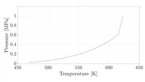
As can be seen in Figure 10, the energy storage is fundamentally linear with temperature and does not change drastically after countercondensation. The total volume-based energy storage is approximately 165 MJ/m3, resulting in a decrease of around 26% with respect to the current layout. The variation of pressure in the process is shown in Figure 11.
In Figure 11 the pressure surge at temperatures higher than countercondensation is shown. An increase of 0.4 MPa between the countercondensation temperature and the maximum temperature is seen. Because of the low critical pressure though, the pressure surge itself is minimal. For comparison, water has a very similar critical temperature to D6, around 674.1 K, and a critical pressure of 22.1 MPa, approximately 23 times larger. For a process at same reduced volume as the one considered and among the same reduced temperatures, the pressure surge would be around 10 MPa instead of 0.4 MPa. As in the ethylene glycol case, the structural requirements given by the 1 MPa operating pressure are by themselves enough to cover the requirement for vacuum in the pressure vessel generated by the decrease in temperature.
Figure 11. Temperature as a function of specific volume and saturation curve for D6
The decrease of the energy density in the D6 case can be an acceptable drawback. The required field for the thermal storage section of Concentrated Solar Power plants is a negligible part of the plant itself. The sharp decrease in maximum pressure on the other hand allows for much simpler and cheaper storage tanks, and higher deployability. This is because the cost of these components is mainly related to safety measures for high pressure and wall thickness. The maximum storage temperature is increased by around 55 K, resulting in better efficiencies during discharge.
A summary of the results obtained in the two cases is shown in Table 4.
Table 4. Summary of the results obtained for ethylene glycol and D6
|
|
Ethylene Glycol |
D6 |
|
Minimum storage temperature [K] |
468.0 base pressure, 646.6 high pressure |
468.0 |
|
Maximum storage temperature [K] |
648.1 base pressure, 699.9 high pressure |
613.0 |
|
Minimum storage pressure [MPa] |
0.09 base pressure, 3.90 high pressure |
0.03 |
|
Maximum storage pressure [MPa] |
4.00 base pressure, 8.20 high pressure |
1.00 |
|
Specific volume [dm3/kg] |
1.34 base pressure, 1.67 high pressure |
1.96 |
|
Storage variation w.r.t current layout [%] |
94.62 |
-26.1 |
|
Maximum storage temperature increase w.r.t. current layout [K] |
130.9 |
55.0 |
In this work the concept of thermal energy storage through closed and constant-volume vapor-liquid systems is applied to the Khi Solar One concentrated solar power plant in Upington, South Africa. A generalized analysis of the performances in a fluid-independent manner is performed to assess the influence of the critical temperature and pressure, and thus choose the most suited fluids for storage. The results are applied with the objective of (i) maximizing the critical temperature and (ii) minimizing the critical pressure. Two fluids, ethylene glycol and D6 siloxane are chosen to comply the first and the second objective respectively. It is shown that:
|
T |
Temperature [K] |
|
P |
Pressure [MPa] |
|
$\hat{u}$ |
Volume-based internal energy, [kJ m-3] |
|
v |
Specific volume [m3 kg-1] |
|
$\omega$ |
Acentric factor [-] |
|
Subscripts |
|
|
c |
Critical |
|
r |
Reduced |
[1] Dincer, I., Rosen, M. (2002). Thermal Energy Storage: Systems and applications. John Wiley & Sons.
[2] Sarbu, I., Sebarchievici, C. (2018). A comprehensive review of thermal energy storage. Sustainability, 10(1): 191. https://doi.org/10.3390/su10010191
[3] Zhao, W., France, D. M., Yu, W., Kim, T., Singh, D. (2014). Phase change material with graphite foam for applications in high-temperature latent heat storage systems of concentrated solar power plants. Renewable Energy, 69: 134-146. https://doi.org/10.1016/j.renene.2014.03.031
[4] Sharma, A., Tyagi, V.V., Chen, C.R., Buddhi, D. (2009). Review on thermal energy storage with phase change materials and applications. Renewable and Sustainable Energy Reviews, 13(2): 318-345. https://doi.org/10.1016/j.rser.2007.10.005
[5] Dusek, S., Hofmann, R. (2019). Modeling of a hybrid steam storage and validation with an industrial Ruths steam storage line. Energies, 12(6): 1014. https://doi.org/10.3390/en12061014
[6] Valenti, G., Seveso, A., Bonacina, C.N., Bamoshmoosh, A. (2019). Assessment of a phase change regenerator for batch industrial dryers. In AIP Conference Proceedings, 2191(1): 020151. https://doi.org/10.1063/1.5138884
[7] Qureshi, Z.A., Ali, H.M., Khushnood, S. (2018). Recent advances on thermal conductivity enhancement of phase change materials for energy storage system: A review. International Journal of Heat and Mass Transfer, 127: 838-856. https://doi.org/10.1016/j.ijheatmasstransfer.2018.08.049
[8] Bamoshmoosh, A., Valenti, G. (2020). Constant-volume vapor-liquid equilibrium for thermal energy storage: Generalized analysis of pure fluids. 75th Congresso Nazionale ATI, 197: 01001. https://doi.org/10.1051/e3sconf/202019701001
[9] Bamoshmoosh, A., Valenti, G. (2021). Constant-volume vapor-liquid equilibrium for thermal energy storage: investigation of a new storage condition for solar thermal systems. In 100% Renewable: Strategies, Technologies and Challenges for A Fossil Free Future, 238: 03004. https://doi.org/10.1051/e3sconf/202123803004
[10] Taravillo, M., Baonza, V. G., Cáceres, M., Núñez, J. (2003). Thermodynamic regularities in compressed liquids: I. The thermal expansion coefficient. Journal of Physics: Condensed Matter, 15(19): 2979. https://doi.org/10.1088/0953-8984/15/19/302
[11] Polimeni, S., Binotti, M., Moretti, L., Manzolini, G. (2018). Comparison of sodium and KCl-MgCl2 as heat transfer fluids in CSP solar tower with sCO2 power cycles. Solar Energy, 162: 510-524. https://doi.org/10.1016/j.solener.2018.01.046
[12] Seitz, M., Johnson, M., Hübner, S. (2017). Economic impact of latent heat thermal energy storage systems within direct steam generating solar thermal power plants with parabolic troughs. Energy Conversion and Management, 143: 286-294. https://doi.org/10.1016/j.enconman.2017.03.084
[13] Martins, M., Villalobos, U., Delclos, T., Armstrong, P., Bergan, P.G., Calvet, N. (2015). New concentrating solar power facility for testing high temperature concrete thermal energy storage. Energy Procedia, 75: 2144-2149. https://doi.org/10.1016/j.egypro.2015.07.350
[14] González-Roubaud, E., Pérez-Osorio, D., Prieto, C. (2017). Review of commercial thermal energy storage in concentrated solar power plants: Steam vs. molten salts. Renewable and Sustainable Energy Reviews, 80: 133-148. https://doi.org/10.1016/j.rser.2017.05.084
[15] Li, J., Gao, G., Kutlu, C. et al. (2019). A novel approach to thermal storage of direct steam generation solar power systems through two-step heat discharge. Applied Energy, 236: 81-100. https://doi.org/10.1016/j.apenergy.2018.11.084
[16] Steinmann, W.D., Eck, M. (2006). Buffer storage for direct steam generation. Solar Energy, 80(10): 1277-1282. https://doi.org/10.1016/j.solener.2005.05.013
[17] Steinmann, W.D., Prieto, C. (2021). Thermal storage for concentrating solar power plants. Advances in Thermal Energy Storage Systems, pp. 673-697. https://doi.org/10.1016/B978-0-12-819885-8.00024-3
[18] Pelay, U., Luo, L., Fan, Y., Stitou, D., Rood, M. (2017). Thermal energy storage systems for concentrated solar power plants. Renewable and Sustainable Energy Reviews, 79: 82-100. https://doi.org/10.1016/j.rser.2017.03.139
[19] Prieto, C., Rodríguez, A., Patiño, D., Cabeza, L.F. (2018). Thermal energy storage evaluation in direct steam generation solar plants. Solar Energy, 159: 501-509. https://doi.org/10.1016/j.solener.2017.11.006
[20] Valenzuela, L. (2017). Thermal energy storage concepts for direct steam generation (DSG) solar plants. Advances in Concentrating Solar Thermal Research and Technology, pp. 269-289. https://doi.org/10.1016/B978-0-08-100516-3.00012-5
[21] Al Kindi, A.A., Pantaleo, A.M., Wang, K., Markides, C.N. (2019). Thermodynamic assessment of steam-accumulation thermal energy storage in concentrating solar power plants. International Conference on Applied Energy, Västerås, Sweden.
[22] Karakurt, A.S. (2017). Performance analysis of a steam turbine power plant at part load conditions. Journal of Thermal Engineering, 3(2): 1121-1128. https://doi.org/10.18186/thermal.298611
[23] Plocker, U., Knapp, H., Prausnitz, J. (1978). Calculation of high-pressure vapor-liquid equilibria from a corresponding-states correlation with emphasis on asymmetric mixtures. Industrial & Engineering Chemistry Process Design and Development, 17(3): 324-332. https://doi.org/10.1021/i260067a020
[24] Lee, B.I., Kesler, M.G. (1975). A generalized thermodynamic correlation based on three‐parameter corresponding states. AIChE Journal, 21(3): 510-527. https://doi.org/10.1002/aic.690210313
[25] Dow Chemical Co, Acidic Thermal Degradation Products of Ethylene Glycol and Propylene Glycol, Form No. C98030.
[26] Angelino, G., Invernizzi, C. (1993). Cyclic methylsiloxanes as working fluids for space power cycles. Journal of Solar Energy Engineering, 115(3): 130-137. https://doi.org/10.1115/1.2930039
[27] Preißinger, M., Brüggemann, D. (2017). Thermoeconomic evaluation of modular organic Rankine cycles for waste heat recovery over a broad range of heat source temperatures and capacities. Energies, 10(3): 269. https://doi.org/10.3390/en10030269
[28] Invernizzi, C.M., Bonalumi, D. (2017). Thermal stability of organic fluids for Organic Rankine Cycle systems. Organic Rankine Cycle (ORC) Power Systems, pp. 121-151. https://doi.org/10.1016/B978-0-08-100510-1.00005-3
[29] Moss, D.R. (2004). "General Design," in Pressure Vessel Design Manual, Third Edition, Gulf Professional Publishing.
[30] Astolfi, M., Romano, M.C., Bombarda, P., Macchi, E. (2014). Binary ORC (organic Rankine cycles) power plants for the exploitation of medium–low temperature geothermal sources - Part A: Thermodynamic optimization. Energy, 66: 423-434. https://doi.org/10.1016/j.energy.2013.11.056
[31] Fernández, F.J., Prieto, M.M., Suárez, I. (2011). Thermodynamic analysis of high-temperature regenerative organic Rankine cycles using siloxanes as working fluids. Energy, 36(8): 5239-5249. https://doi.org/10.1016/j.energy.2011.06.028
[32] Casati, E., Galli, A., Colonna, P. (2013). Thermal energy storage for solar-powered organic Rankine cycle engines. Solar Energy, 96: 205-219. https://doi.org/10.1016/j.solener.2013.07.013