Bernardo Buonomo | Vincenzo Ceraso | Oronzio Manca | Sergio Nardini* | Renato Elpidio Plomitallo | Silvio Vigna
OPEN ACCESS
This paper presents a novel whey drying plant assisted by solar energy. In Italy, the whey is mostly used for feeding pigs and, regrettably, in the worst cases, it is discharged against the regulations to avoid significant disposal costs. Current technologies for the whey drying process are very polluting and expensive. Therefore, it is necessary to evolve the technologies for such processing to safeguard the environment and reduce operating costs.
The plant is equipped by concentrated solar collectors which process the heat necessary to evaporate the whey in a vacuum dryer at a temperature equal to 65°C. In addition to the solar collectors, a boiler is present. The processed product is then deposited in a storage tank for its conservation. This thank is kept at a low temperature by an Ice Tank and an absorption refrigeration (H2O-BrLi) chiller. The warm water, which is heated by the field of the solar collectors, feeds the absorption chiller. A photovoltaic system electrically assists the pumps, thus making the entire system energy sustainable. The dynamic simulation of the processing of this drying plant is carried out by means of the TRNSYS software for the entire year. Solar fraction and efficiency of collectors are evaluated.
whey, solar collector, vacuum evaporation, TRNSYS, solar energy
In the recent years, more and more attention has been paid to the use of renewable energy sources in the industrial and civil sectors for the reduction of CO2 emissions and for the reduction of energy consumption from exhaustible sources.
Solar energy is a clean, unlimited and environmentally friendly energy source. In fact, it is the most important source of renewable energy. Solar energy can be utilized by photovoltaic (PV) cells by the direct conversion of solar energy to electrical energy or by solar thermal collectors using the direct conversion of solar energy to heat energy (solar thermal).
Capturing, storing and using solar energy at reasonable prices is the goal in utilization of solar energy. The solar thermal system is the most common means of solar energy, because to the technical feasibility and economic viability compared with other forms of solar energy usage. The solar collector absorbs solar radiation and transfers heat to the working fluid. The biggest problem of the use of solar energy for day-to-day energy requirement is yearlong performance predictability. The performance of solar collectors is influenced by product configurations, surface area and local metrological conditions. Another problem is to obtain the performance of solar collectors by experimental investigations. In fact, the experimental method to predict the effect of the parameters that influenced solar collectors is time consuming and costly, so the alternative way to analyse the solar hot water system for long-term performance is the use of simulation software [1].
The development of modelling and simulation of solar collectors may be categorized in three phases: numerical techniques; analog computer based and modern digital computer having user friendly GUI and versatile report generation capability. Nowadays, this kind of simulations is not only limited to academic interest, but real-life problems and professional interest. Initially the system was owned by a group of university and high-profile research institutes, but slowly it has become accessible to a mass [2].
In the last years, many authors have used TRNSYS for numerical simulation of their plants [3]. For example, Dagdougui et al. [4] have investigated the effect of the different parameters which may affect the performance of the flat plate solar collector to support decision makers in the definition of the optimal water flow and of the optimal collector flat area. Hazami et al. [5] have simulate and experimentally validate a TRNSYS model of a type of domestic solar water heating system (DSWH) based on evacuated tube collector (ETC) installed in Tunisia. Recently, Tiwari et al. [1] have presented a domestic solar hot water system (SHWS) modelled using TRNSYS and they have evaluated the long-term performance of the system for Indian climatic condition.
This paper presents a novel whey drying plant assisted by solar energy. In Italy, the whey is mostly used for feeding pigs and, regrettably, in the worst cases, it is discharged against the regulations in order to avoid significant disposal costs. Current technologies for the whey drying process, which mainly involves the use of high-pressure pumps with the help of osmosis filtration systems, which are subject to continuous maintenance and with constant and very high energy and maintenance costs, are very polluting and expensive. Therefore, it is necessary to evolve the technologies for such processing to safeguard the environment and reduce operating costs.
There are two main water removal processes that are used in the dairies and feed powder industries: Vacuum evaporation to remove the main water fraction and transform a low-viscosity liquid into a relatively highly viscous concentrate and Spray drying to transform this concentrate into powder by spraying small droplets into a flow of hot air [6, 7]. With Vacuum evaporation it is possible to remove water at low temperature by working at low pressure.
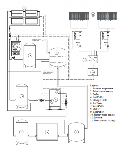
The plant [8] is equipped by concentrating solar collectors which process the heat necessary to evaporate the whey in a special dryer, as reported in Figure 1.
Figure 1. Whey drying system [8]
A vacuum pump is used to evaporate water from whey at a temperature equal to 65°C and a pressure equal to 0.025 MPa. In addition to the solar collectors, a boiler, which is active if the weather conditions are not favourable, is also present. A hot puffer, linked to the solar collectors and boiler, is present. This puffer improves the thermal storage of hot water. The processed product is then deposited in a storage tank for its conservation. This thank is kept at a low temperature by an absorption refrigeration (H2O-BrLi) chiller. The warm water, which is heated by the field of the solar collectors, feeds the absorption chiller. A cold puffer is downstream the chiller. To reach the range of temperature between 6-8°C in the storage tank, a continuous production of chilled water is needed, so an ice accumulation tank is added to the plant. A photovoltaic system electrically assists the pumps, thus making the entire system energy sustainable. This technical solution has the advantage of being cheaper than the one currently in use.
To remove 1 kg of water from whey at 65°C, an energy consumption is necessary between 2600–3100 kJ/kg [7]. In this case, the energy consumption is about 2450 kJ/kg, because the whey is about at 40°C when it arrives in the dryer. However, a single effect vacuum evaporator is considered. For this reason, a solar plant of 50 m2 and a boiler of 42 kW are considered for the mass flowrate of 60 kg/h of whey.
The solar plant is designed using the following Eq. (1) for the collector’s efficiency:
$\eta=a_{0}-a_{1} \cdot \frac{\Delta T}{G}-a_{2} \cdot \frac{(\Delta T)^{2}}{G}$ (1)
where, η is the solar collector efficiency; $\frac{\Delta T}{G}$ is the designed temperature jump between internal collector temperature and external temperature divided by solar radiation; a0, a1 and a2 are three parameters that are given by the collector’s builder. Considering that in Naples the average solar radiation is 1500 kWh/m2 and the maximum is 1700 kWh/m2 per year, also considering a collector’s efficiency between 50-60%, for the designed 50 m2 it is possible produce about 30-35% of annual request of the plant if it works 8 h per day.
The annual request of the plant is estimated considering the energy consumption, Q, for the evaporation of 60 kg of water every hour:
$Q=m \cdot \Delta h_{e v}$ (2)
Finally, the energy absorbed by chiller is added.
To evaluate the solar contribution, solar fraction can be calculated as follow Eq. (3):
$S f=1-\frac{\int \dot{Q}_{a u x}}{\int \dot{Q}_{\text {demand }}}$ (3)
where, $\dot{Q}_{\text {aux }}$ is the heat transfer rate of the boiler, in this case, and $\dot{Q}_{\text {demand }}$ is the heat transfer rate of the hot puffer that supply energy for the vacuum dryer and the chiller.
Solar collectors can be categorised into three types based on the temperature range: low temperature, medium temperature, high temperature. Among all, flat plate collectors (FPC) are mostly used in household and low temperature (45°C-100°C) applications because of their low cost. Parabolic trough collectors (PTC), Linear Fresnel reflectors, compound parabolic collectors (CPC) are used for the medium temperature applications with temperatures up to 400 °C. They are used for industrial processes. For the power-producing heat processes there are solar collectors at high temperature range with temperature up to 1500°C. So, in the whey dryer plant the choice is to use PTC solar collectors.
TRNSYS is a transient system simulation application that is used to model and simulate the performance and the behaviour of systems as a function of time. To simulate the complete system in TRNSYS, the first step is to identify the individual components whose collective performance describes the performance of the whole system [1].
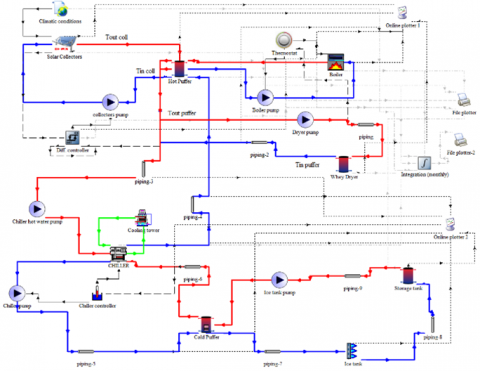
To evaluate the technical feasibility of the plant and to evaluate its performance, the whey system is modelled and simulated in TRNSYS. In this simulation TRNSYS 17 [9] is used. The plant is shown in Figure 2.
Figure 2. Whey dryer plant simulated in TRNSYS environment
Climatic conditions are considered by the Type 15-6 and it is added to take weather data of Naples from Meteonorm library, using the plug-in Weather data. PTC panels are the Type 1288, present only in the TESS library [10], that is used to simulate an array of parabolic through collectors. Some data are required here as number of collectors in series, the total surface, the collector slope. The differential controller is the Type 2b that makes a control on collectors’ pump, when the temperature jump between collectors and hot puffer is 10°C, the pump runs and the collector’s fluid pass through the hot puffer, however the pump is stopped when the temperature jump is about 2°C. Piping is the Type 31 used for simulating piping. The pumps are the Type 3b that simulate a pump with different velocities. The hot puffer is the Type 534. It represents a cylindrical storage tank; in its plugin it is easier to model a puffer with desired characteristics. Type 1502 is a thermostat and Type 700 is the Boiler. The Whey Dryer is the Type 4a that represents, in our case the vacuum evaporator. In the second half of Figure 2 there are, also: Type 107 that simulate a single-effect hot-water fired absorption chiller; Type 510 that is the cooling tower for the chiller circuit; the chiller controller is the Type 1503, that makes a control on chiller fluid outlet temperature; the cold Puffer is the Type 534-coiled; the Ice Tank is the Type 1246 that models an external, proportionally controlled fluid cooler. In the end, the storage tank is the Type4a that models a stratified tank having fixed inlet positions.
As shown in Figure 2, the hot puffer has two heat exchangers, the first for the solar collectors, that is allocated in the bottom nodes, and the second for the boiler, that is allocated in the top nodes. The boiler is turned off by thermostat when the hot fluid, that passes through the dryer, reaches the temperature of 77°C. In fact, for this fluid that passes also through the hot puffer, the target is to reach a temperature between 75°C and 80°C. So, also the hot fluid for the absorption chiller usage reaches the same temperature field. The whey, at the flowrate of 60 kg/h, is dried in the vacuum evaporator. Every 1 kg of whey contains 0.065 kg of dry whey [6]. The mass flow rate of concentrate at the evaporator outlet depends by the mass concentration of the dry whey that is between 36% and 60% of the concentrate. This mass is allocated in the storage tank that it must be in a temperature range between 4-10°C. For this reason, the chiller only keeps the cold puffer at 7°C, so its power demand, that is delivered by hot puffer, is low. For cooling the storage tank, another fluid passes through the cold puffer and the Ice Tank. The Ice Tank makes a continuous production of chilled water with its own refrigeration unit. The fluid temperature can reach a value of 1°C. After cooling the storage tank, the fluid return in the cold puffer.
In this model a solar field of 50 m2 is simulate. It is composed by an array of six collectors in series. Table 1 summarizes the plant characteristics.
Table 1. Parameters of the plant
|
Parameters |
Val. |
Unit |
|
Solar collectors’ surface |
50 |
m2 |
|
Boiler’s power |
42 |
kW |
|
Hot puffer volume |
2200 |
L |
|
Hot fluid mass flowrate |
3522 |
kg/h |
|
Hot fluid return temperature |
65 |
°C |
|
Whey initial temperature |
40 |
°C |
|
Whey mass flowrate |
60 |
kg/h |
|
Chiller nominal power |
17 |
kW |
|
Cold puffer volume |
800 |
L |
|
Ice tank nominal power |
12 |
kW |
|
Storage tank volume |
300 |
L |
|
Dry whey mass flowrate |
10 |
kg/h |
In TRNSYS it is possible to estimate the solar collectors’ efficiency [11], that give us a measure of monthly or seasonal collector thermal performance, using the follow equation:
$\eta=\frac{\int \dot{Q}_{\text {solar }}}{A_{\text {solar }} \int G}$ (4)
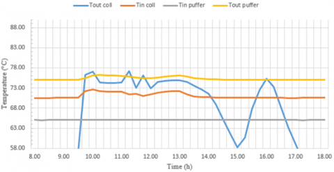
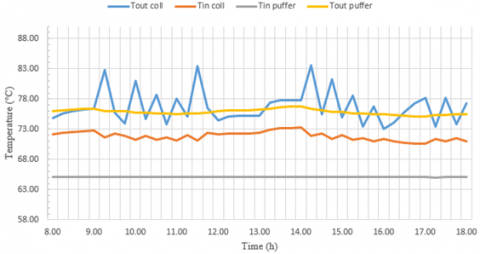
The simulation in TRNSYS is performed for the entire year. So, 8760 h are simulated with a time step of 0.25h. The plant is working continuously, that is 24 h a day. The inlet and outlet solar collectors’ temperatures and the inlet and outlet hot puffer temperatures for two arbitrary days are shown in the Figures 3 and 4. The selected days are the number 186 of the year (July 4) and the number 355 of the year (December 20).
In Figure 3 and Figure 4 the temperatures are shown in a typical winter and summer day, respectively. The hot puffer temperatures are referred to vacuum dryer temperatures. The inlet hot puffer temperature is the outlet dryer temperature. The outlet hot puffer temperature is the inlet dryer temperature. The measure starts at 8:00 and stops at 18:00.
Figure 3. Temperatures of a typical winter day (December 20)
Figure 4. Temperatures of a typical summer day (July 4)
In a typical winter day, the collectors’ inlet temperature can be higher than the outlet temperature, this can happen because the pump is turned off and the inlet collector temperature is taken by the outlet temperature from the heat exchanger in the hot puffer, so the hot puffer never heats up the collectors. In fact, inlet collectors’ temperature never decreases, but it increases only when the pump is turned on. As reported in previous figures, the system can reach the target temperature of collectors and the target for the inlet temperature of vacuum evaporator. In fact, this temperature is between 74°C - 77°C for all time. Furthermore, the collectors’ temperature often reaches the 80°C, so they can active the collectors pump and the collectors fluid can pass through hot puffer, so the collectors exchange energy with puffer and collectors temperature decreases. Sometimes the collectors’ temperature is over 80°C. The inlet temperature of puffer is constant at 65°C, because this is the outlet temperature of dryer.
A problem is present in the night, when the collector pump is off, because the temperature of solar collectors, especially in the winter, are very low. Sometimes the temperature in the winter’s nights can reach the value of 0°C, so a good insulation of collectors’ pipes is required. This problem is not present for the hot puffer because the collectors’ pump is off in this time.
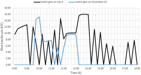
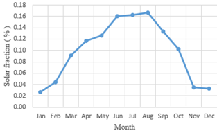
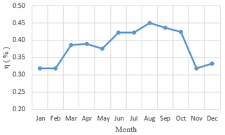
In Figure 5 is shown a comparison between the useful energy gain of solar collectors for a typical summer day and for a typical winter day. This gain is calculate taking the mass flowrate of collectors’ pump and multiplying it for the fluid specific heat and for the temperature jump between inlet and outlet temperature of collectors’ circuit. How it can be seen in Figure 5, in a winter day the solar contribution is sometimes zero. To take in account how much greater is the contribution of solar collectors, it is needed calculate the monthly solar fraction using Eq. (3). The solar fraction is shown in Figure 6. Furthermore, the monthly solar collectors’ efficiency, which is calculated by Eq. (4), is shown in Figure 7.
As expected, the average solar fraction is about 10% when the plant works 24 h a day.
The minimum solar fraction value is reached in January and the maximum is in August. The maximum value of solar fraction is equal to 16,7%. The collector monthly efficiency, that is shown in Figure 7, varies between 31% (in January) and 45% (in August). However, the performances are referred to six PTC in series.
Figure 5. Useful gain of solar collectors on July 4 and on December 20
Figure 6. Monthly solar fraction
Figure 7. Solar collectors’ monthly efficiency
The aim of this paper is to verify the feasibility of an innovative whey dryer plant assisted by solar energy through Parabolic trough collectors. The simulation is performed by means of the TRNSYS software. The system processes 60 kg/h of whey. A boiler of 42 kW with a solar plant of 50 m2 is the heating system for the plant. One year is simulated with a time step of 0.25 h. In the simulation the plant works 24 h a day. The plant guarantees the operative conditions of the system all year long. The maximum value of the Solar fraction is equal to 0.14 and is reached in August because the plant work continuously all day. To better evaluate the plant, a one-year simulation with the plant working 8 h a day is required. Furthermore, a bigger solar plant is required to increase the solar fraction.
|
a0 |
Optical efficiency, - |
|
a1 |
Efficiency slope, kJ h−1m−2 K−1 |
|
a2 |
Efficiency curvature, kJ h−1m−2 K−2 |
|
Asolar |
Solar collectors’ total surface, m2 |
|
G |
Available global solar irradiance, kJ h-1 m-2 |
|
m |
Mass, kg |
|
$\dot{Q}_{\text {aux }}$ |
Heat transfer rate of auxiliary, kJ/h |
|
$\dot{Q}_{\text {demand }}$ |
Required heat transfer rate, kJ/h |
|
$\dot{Q}_{\text {solar }}$ |
Useful energy gain, kJ/h |
|
Sf |
Solar fraction, - |
|
Tincoll |
Solar collectors’ inlet temperature |
|
Toutcoll |
Solar collectors’ outlet temperature |
|
Tinpuffer |
Inlet puffer temperature |
|
Toutpuffer |
Outlet puffer temperature |
|
Greek symbols |
|
|
Δhev |
Evaporation’s enthalpy, kJ kg-1 |
|
ΔT |
Temperature jump, K |
|
η |
Collectors’ efficiency |
|
Subscripts |
|
|
CPC |
compound parabolic collector |
|
DSWH |
domestic solar water heating system |
|
ETC |
evacuated tube collector |
|
FPC |
flat plate collector |
|
H2O-BrLi |
Water- Lithium bromide |
|
PTC |
Parabolic trough collector |
|
PV |
Photovoltaic |
|
SHWS |
solar hot water system |
[1] Tiwari, A.K., Gupta, S., Joshi, A.K., Raval, F., Sojitra, M. (2020). TRNSYS simulation of flat plate solar collector based water heating system in Indian climatic condition. Materials Today: Proceedings. https://doi.org/10.1016/j.matpr.2020.08.794
[2] Shrivastava, R.L., Kumar, V., Untawale, S.P. (2017). Modeling and simulation of solar water heater: A TRNSYS perspective. Renewable and Sustainable Energy Reviews, 67: 126-143. https://doi.org/10.1016/j.rser.2016.09.005
[3] Sudhakar, K., Jenkins, M.S., Mangal, S., Priya, S.S. (2019). Modelling of a solar desiccant cooling system using a TRNSYS-MATLAB co-simulator: A review. Journal of Building Engineering, 24: 100749. https://doi.org/10.1016/j.jobe.2019.100749
[4] Dagdougui, H., Ouammi, A., Robba, M., Sacile, R. (2011). Thermal analysis and performance optimization of a solar water heater flat plate collector: application to Tétouan (Morocco). Renewable and Sustainable Energy Reviews, 15(1): 630-638. https://doi.org/10.1016/j.rser.2010.09.010
[5] Hazami, M., Kooli, S., Naili, N., Farhat, A. (2013). Long-term performances prediction of an evacuated tube solar water heating system used for single-family households under typical Nord-African climate (Tunisia). Solar Energy, 94: 283-298. https://doi.org/10.1016/j.solener.2013.05.020
[6] Schuck, P., Jeantet, R., Tanguy, G., Méjean, S., Gac, A., Lefebvre, T., Martineau, C. (2015). Energy consumption in the processing of dairy and feed powders by evaporation and drying. Drying Technology, 33(2): 176-184. https://doi.org/10.1080/07373937.2014.942913
[7] Camci, M. (2020). Thermodynamic analysis of a novel integration of a spray dryer and solar collectors: A case study of a milk powder drying system. Drying Technology, 38(3): 350-360. https://doi.org/10.1080/07373937.2019.1570935
[8] Sun, ENERGY EUROPE SRL, “Sistema per l’evaporazione e\o concentrazione di un liquido mediante l’energia solare”, Patent n. 102017000020844, Feb. 24, 2017.
[9] TRNSYS, A transient system simulation program (Version 17) manual.
[10] TESS component libraries.
[11] Khan, M.S.A., Badar, A.W., Talha, T., Khan, M.W., Butt, F.S. (2018). Configuration based modeling and performance analysis of single effect solar absorption cooling system in TRNSYS. Energy Conversion and Management, 157: 351-363. https://doi.org/10.1016/j.enconman.2017.12.024