Luca Piancastelli* | Patrich Ferretti | Gian Maria Santi | Alessandro Scaltrini | Stefano Cassani | Federico Calzini
OPEN ACCESS
Small, turbine-powered eAPUs (electric Auxiliary Power Unit) have poor off-design performance and efficiency. Turbo eAPUs remain competitive where efficiency is sacrificed to lightness and compactness. The first part of this paper summarizes the transformation of a very efficient, very large automotive turbocharger into an eAPU. A satisfactory solution for the design of the heavy fuel combustor has been found on the Giandomenico’s site. The performance of the APU is evaluated at the Garrett nominal air conditions (T0=302.6 K, p0=0.962 bar, dry air). The turbogas has an approximately linear braking torque from 50% to 100% load at nearly maximum efficiency. Below 50% load, it is more convenient to vary the maximum temperature of the cycle and adjust the generator torque. However, a better compromise can be obtained by coupling the APU with a battery that would supply the electric power under 50% load. The use of a recuperator is not convenient due to the increase in volume and the additional complication. The problem of the intake air filtering is particularly serious in dirty/sandy ground applications. Regarding efficiency, the turbogas is no match for the diesel eAPUs.
APU, Hybrid turbochargers, Efficiency, Mapping
Micro and small turbines have never been a success due to poor efficiency and poor off-design performance when compared with piston engines [1-8]. Turbo power generation remains a possibility where efficiency is sacrificed to compactness, reliability and simplicity. This will be particularly true in the near future with off-the-shelf, commercial, mass produced eMTU (electric Motor Turbine Units) that are becoming available. In this case, even the electric generator is already integrated into the hybrid, automotive turbocharger and it is sufficient to add the combustor and to choose a turbocharger with the best technology available. In short time also the units to convert the output power from the generator to the 48V of heavy vehicle applications will be available. The price of the APU will be then extremely low because of automotive mass production. Availability and optimal cost-effectiveness make the conversion of hybrid-turbocharger to eAPU easy and affordable. This is the theory. For practical applications, many obstacles remain. The first and most important one is the combustion chamber geometry, which proved to be critical for the specific application. A second problem lies in the bearing selection to make the application reliable. A third problem is the necessity to map the most convenient working point for every power output and ambient conditions combination. Finally, the starting phase remains critical. In addition, scaling down gas turbines technology still depletes efficiency, especially when compared with the 50% value of modern off-the-shelf common rail diesel generators. In the past, several failed attempts have been made to develop microturbines for propulsion and electric power generation. The only mass-produced commercially available small turbines are turbojets for small model airplanes. In fact, small-scale effects prevent the obtainment of high aerodynamic efficiency. In general, a small turbogas faces high viscous losses due to low Reynolds numbers, high tip clearances and lower compressor and turbine efficiency. These problems are added to the larger heat losses due to high area to volume ratios and increased power loss in auxiliary systems. The development of a scaled-down, brand new micro turbine is prohibitively expensive and ineffective due to the very small size of the components. Using an automobile turbocharger is a cost-effective opportunity to reduce the cost for an inefficient thermal machine. The huge investments in small automotive turbochargers make them sufficiently efficient to sustain stable gas turbine cycles. Some studies have shown that an efficiency in the range of 10% are easily obtainable without the use of a recuperator that increases size and cost. In the last 10 years the increasing price of fuel has boosted the research on the utilization of the exhaust gas of vehicles with energy saving and emission reduction. Even when discharged by a turbocharger, engine exhaust gas has a residual energy in terms of pressure and heat. Volvo, the truck manufacturer, has patented an application where a secondary turbine is coupled to the main drive to rescue energy otherwise wasted. This application is common in many trucks of this Company. An alternative is to rescue this energy through an electric generator directly coupled to the turbocharger shaft. The hybrid turbocharger obtained in this way is used to recover energy and to reduce the turbolag, by providing torque to the turbo unit on acceleration. A few papers evaluated that the use of a hybrid turbocharger reduces fuel consumption up to 5% in long motorway runs. This is aligned to the figures already obtained with mechanical systems in Volvo trucks. This advantage, added to the possibility to avoid double turbocharger arrangements, makes the application of hybrid turbochargers convenient even in energy consuming cars like SUVs (Sport Utility Vehicle). In any case, it is also possible to couple a small advanced electric generator on existing standard commercial turbochargers. A very good commercially available alternative are eAPUs (electric Auxiliary Power Unit) certificated for small airplanes and helicopters. Unfortunately, these power units are designed for jet fuels (only) with power output larger than 30 kW.
This paper shows how it is possible to develop a very cost-effective turbo-generator for airborne and vehicular eAPUs, ground power units (GPU) and hybrid propulsion systems. This first part of this paper shows the advantages and the limits of an up-to-date simple and reliable turbogenerator obtained from a modern, commercial, automotive turbocharger. Mapping and combustion chamber design for heavy fuels are also briefly introduced. For this purpose, a turbogenerator is designed from a slightly improved Garrett GTX5533-98. The Garrett GTX5533 has a very modern and optimized design and it is a very large unit for automotive applications. It enjoys all the advantages of being large in terms of efficiency and maximum output pressure. It also comes with ball bearings that need less lubrication and have less friction on starting. The related problem of reliability and tolerances have been already solved by the Garrett Company Engineers. Further improvements introduced on the original turbocharger are a new turbine and an upgraded compressor. The new turbine wheel has an improved material that can withstand 1050 DEG C continuous temperature. A liner has also been added to reduce the gap between blades and casing in the compressor. The blades carve the inner liner without damage in case of small interference. Finally, the compressor impeller has been polished to further improve efficiency. It is also possible to install a titanium alloy impeller for improved high altitude performance, but this improvement is beyond the scope of this first part of the paper. The results obtained are the most cost-effective starting from commercial turbocharger technology.
This first part of the paper deals with dry air at Garrett standard air conditions (T0=302.6 K, p0=0.962 bar). A pressure drop of 0.0135 bar in the intake and an overpressure on the exhaust is included in the calculations (1)(2). The coefficients and the numerical values introduced in this paper come from tests on the real eAPU.
${{p}_{1}}={{p}_{0}}-0.0135$ (1)
${{p}_{4}}={{p}_{0}}+0.0135$ (2)
The pressure after the compression is given by Eq. (3).
${{p}_{2}}={{p}_{1}}{{\beta }_{c}}$ (3)
${{T}_{2is}}={{T}_{1}}\cdot \beta _{^{c}}^{\frac{R}{{{c}_{p}}}}$ (4)
${{T}_{2}}={{T}_{1}}+({{T}_{2is}}-{{T}_{1}})\cdot {{\eta }_{c}}$ (5)
Eqns. (4) and (5) are for the isentropic and real compression. The combustion chamber pressure drop (6) reduces the pressure at the intake of the turbine.
${{p}_{3}}=0.95{{p}_{2}}$ (6)
$\beta =\frac{{{p}_{3}}}{{{p}_{4}}}\to {{T}_{4is}}={{T}_{3}}\cdot \frac{1}{{{\beta }^{\frac{R}{{{c}_{pf}}}}}}$ (7)
${{c}_{pf}}=0.977{{c}_{p}}$ (8)
${{T}_{4}}={{T}_{3}}+({{T}_{3}}-{{T}_{4is}})\cdot {{\eta }_{T}}$ (9)
Eqns. (7-9) complete the basic calculations. Then it is possible to calculate approximately the shaft power output to the electric generator (10).
$P=\dot{m}{{\eta }_{0}}{{c}_{pf}}\left( ({{T}_{3}}-{{T}_{4}})-{{c}_{p}}({{T}_{2}}-{{T}_{1}}) \right)$ (10)
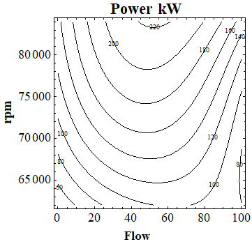
By repeating the calculation of Eqns. (1-10) on the compressor and turbine working points, it is possible to obtain the map of Figure 1. The flow is 0% at 0.58 compressor efficiency (stall) and 100% at choke. Figure 1 shows that at approximately 50% of the maximum flow the output power is near to the maximum for all the useful rpm values. Eq. (11) outputs an approximate value of the efficiency.
Figure 1. Power kW with shaft rpm and air flow [%]
$\eta =\frac{\dot{m}\left( {{c}_{pf}}{{T}_{3}}-{{c}_{p}}{{T}_{2}} \right)}{P}$ (11)
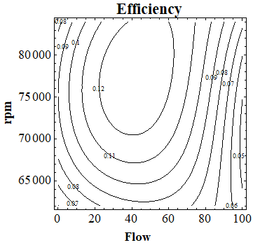
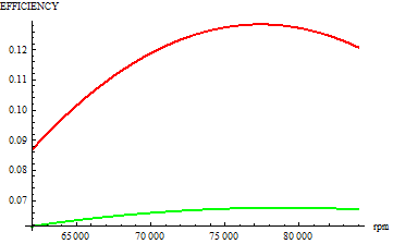
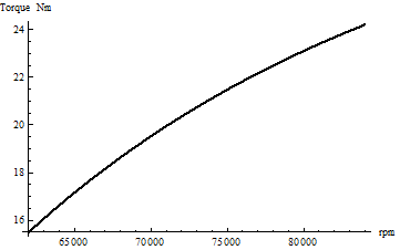
The contour graph of Figure 2 from Eq. (11) shows that the turbogas finds its best efficiency also at 50% of the maximum flow. Therefore, it is possible to run the turbogas at maximum efficiency and maximum power by varying the shaft rotational velocity from 62,000 up to 84,000rpm with an output from 100kW to 220kW. The temperature T3 is constant at its maximum value (1050 DEG C) in order to maximize efficiency. Huge penalties come from the reduction of maximum turbine inlet temperature (EGT – Exhaust Gas Temperature) T3 (Figure 3). The torque to rpm curve is nearly linear for 50% flow and T3=1050 DEG C (Figure 4) for power in the 50-100% range. This is compatible with a brushless generator with a constant load. Therefore, the turbo-generator may work with a battery that supplies power at low loads (under 50%). The generator would work only at high loads. A high voltage, high frequency permanent magnet generator may be directly installed on the shaft. The output may be converted to electric parameters compatible with the battery; the battery would then supply the power to the vehicle network.
Figure 2. Approx. efficiency with rpm and air flow [%]
Figure 3. Efficiency at 50% of the max (choke) flow for T3=1050 DEG C (red) and T3=750 DEG C (green).
Figure 4. Torque at 50% of the (choke) flow for T3=1050 DEG C
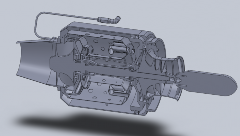
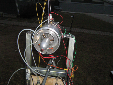
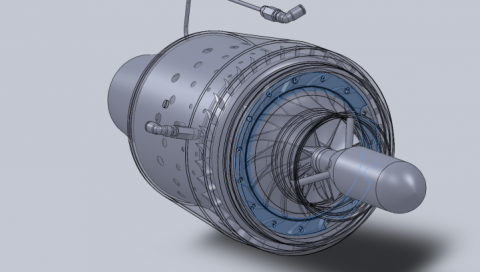
The turbocharger has a compressor and a turbine already matched together, therefore this basic unit does not need further modifications. The design of a heavy fuel combustor proved to be a major challenge. The initial design of Figures 5 and 6 proved to be unable to start due to poor design. An improved version with variable geometry vaned diffuser proved to be slightly better (Figure 7). The best solution was found by using a design from the US website of Mr. Don Giandomenico [https://www.rcdon.com/index.html]. The combustor includes a heating system to improve fuel vaporization and combustion. Its efficiency has been evaluated to be around 95% with automotive diesel fuel. At the moment of the projects of Figures 5 to 7, the Authors did not have a working CFD (Computational Fluid Dynamics) software. Afterwards, the design of Mr. Giandomenico was improved with CFD up to the final version of Figures 8 and 9.
Figure 5. The initial design
Figure 6. The initial design on the test bench
Figure 7. The improved design with the variable geometry vaned diffuser
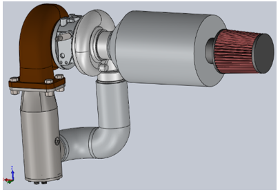
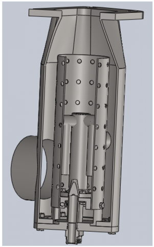
Actually, the tests were made without the air filter shown in Figure 8. The air filter is a problem for turbogas since they are air cooled and the volumetric flow at full power is relatively huge. In case of use of the turbogenerator in dirty environments, the filter may be quite large and may require a suction system to expel the sand. In helicopters, centrifugal filters on the intake have been implemented. Unfortunately, they proved insufficient for ground vehicles. The generator is assembled with a magnetic coupling to the shaft on the impeller side. The maximum torque obtainable from the motor/generator is tiny and the low friction of roller bearings is advantageous on starting.
Figure 8. The final design of the generator
Figure 9. The combustor
The first part of this paper describes the transformation of one the best available automotive turbocharger into an eAPU. After a long design and experimental work, a satisfactory configuration for the heavy fuel combustor has been found on the Don Giandomenico site. The turbocharger is prepared with a high temperature turbine and a liner to reduce the impeller to casing gap. The performance of the APU has been evaluated at the Garrett nominal air conditions (T0=302.6 K, p0=0.962 bar, dry air). It was found that the turbogas has an approximately linear braking torque from 50% to 100% in nearly maximum efficiency conditions. This result can be obtained by varying the turbogas speed. This solution is ideal for a brushless generator. In this condition, the inlet turbine gas temperature is kept at the maximum value (1,050 DEG C) that, in this case, corresponds also to the maximum efficiency. Under 50% load a more sophisticated control to find the best combination between turbine inlet temperature and rpm is required. Even under 50% power output, the point in which the airflow corresponds to the best compressor efficiency can be assumed as nearly ideal for the turbogas. Therefore, under 50% power, the EGT (Exhaust Gas Temperature) T3 should be reduced with huge penalties in fuel consumption. An optimum compromise can be found with a battery that would supply the electric power under 50% load. The use of a recuperator is not convenient due to the huge increase in volume and the additional complication. The problem of the intake air filtering is particularly serious in dirty/sandy ground applications. A cumbersome filter with a suction system may be necessary. The advantage when compared with a diesel common rail generator is the simplicity, the volume, the mass and the maintenance requirements [9-22]. However, the turbogas has much lower efficiency. In the second part of this paper, the performance of the turbogas with OAT (Outside Air Temperature), altitude and humidity is analyzed.
|
po |
Ambient pressure bar (0.962 bar) |
|
T0 |
Ambient temperature K (302.6 K) |
|
p1 |
Inlet pressure bar |
|
T1 |
Inlet temperature K (302.6 K) |
|
βc |
Compressor pressure ratio |
|
ηc |
Compressor efficiency |
|
R |
Ideal gas constant |
|
cp |
Specific heat of air at constant pressure kJ (kg K)-1 |
|
p2 |
Pressure at compressor outlet bar |
|
T2is |
Temperature at compressor outlet for isentropic compression K |
|
T2 |
Temperature at compressor outlet for real compression K |
|
p3 |
Pressure at turbine inlet bar |
|
T3 |
Temperature at turbine inlet K |
|
cpf |
Specific heat of exhaust at constant pressure kJ (kg K)-1 |
|
p4 |
Pressure at turbine outlet bar |
|
T4is |
Temperature at turbine inlet isentropic expansion K |
|
ηT |
Turbine efficiency |
|
T4 |
Temperature at turbine outlet K |
|
po |
Ambient pressure bar |
|
T0 |
Ambient temperature K |
|
p1 |
Inlet pressure bar |
|
T1 |
Inlet temperature K |
|
R |
Ideal gas constant kPa m3 (kg K)-1 (0.287) |
|
p2 |
Pressure on compressor outlet |
|
T2is |
Temperature on compressor outlet for isentropic compression K |
|
T2 |
Temperature at compressor outlet for real compression K |
|
p3 |
Pressure at turbine inlet |
|
T3 |
Temperature at turbine inlet K |
|
p4 |
Pressure at turbine outlet |
|
T4is |
Temperature at turbine outlet isentropic expansion K |
|
η0 |
Mechanical efficency |
|
m’ |
Mass flow rate kg s-1 |
|
P |
Power output W |
[1] Piancastelli, L., Scaltrini, A., Santi, G.M. (2020). Critical design issues of heavy fuel turbogas generators derived from automotive turbochargers. Part II: The improved mach method for off design performance tuning. TECNICA ITALIANA-Italian Journal of Engineering Science, 64(2-4): 325-330. https://doi.org/10.18280/ti-ijes.642-430
[2] Piancastelli, L., Burnelli, A., Cassani S. (2017). Validation of a simplified method for the evaluation of pressure and temperature on a RR Merlin XX head. International Journal of Heat and Technology, 35(3): 549-558. https://doi.org/ 10.18280/ijht.350311
[3] Piancastelli, L., Cassani, S. (2017). Maximum peak pressure evaluation of an automotive common rail diesel piston engine head. Journal of Engineering and Applied Sciences, 12(1): 212-208.
[4] Piancastelli, L., Cassani, S. (2017). Power speed reduction units for general aviation Part 2: General design, optimum bearing selection for propeller driven aircrafts with piston engines. Journal of Engineering and Applied Sciences. 12(2): 544-550.
[5] Piancastelli, L., Cassani, S. (2017). High altitude operations with piston engines power plant design optimization Part V: Nozzle design and ramjet general considerations. Journal of Engineering and Applied Sciences. 12(7): 2242-2247.
[6] Piancastelli, L., Gardella, M., Cassani, S. (1819). Cooling system optimization for light diesel helicopters. Journal of Engineering and Applied Sciences, 12(9): 2803-2808.
[7] Piancastelli, L., Cassani, S. (1819). On the conversion of automotive engines for general aviation. Journal of Engineering and Applied Sciences, 12(13): 4196-4203.
[8] Piancastelli, L., Cassani, S. (2017). Convertiplane cruise performance with contra-rotating propeller. Journal of Engineering and Applied Sciences, 12(19): 5554-5559.
[9] Luca, P., Marco, C., Stefano, C., Federico, C., Pezzuti, E. (2018). Intake and exhaust position optimization in the cooling duct of diesel helicopters. ARPN Journal of Engineering and Applied Sciences, 13(17): 4811-4819.
[10] Piancastelli, L., Cassani, S., Pezzuti, E., Pompei, L. (2018). Multi-objective optimization of the cooling system of a diesel helicopter. ARPN Journal of Engineering and Applied Sciences, 13(16): 4610-4616.
[11] Piancastelli, L., Cassani, S., Pezzuti, E., Cassani, S. (2006). Energy transfer from airborne high altitude wind turbines: Part I, A feasibility study of an autogirogenerator from an existing helicopter. ARPN Journal of Engineering and Applied Sciences, 14(7): 1407-1413.
[12] Piancastelli, L., Cassani, S. (2019). Energy transfer from airborne high altitude wind turbines: Part II performance evaluation of an autogiro-generator. ARPN Journal of Engineering and Applied Sciences, 14(17): 2972-2979.
[13] Piancastelli, L., Sportiello, L., Pezzuti, E., Cassani, S. (2019). Study and optimization of advanced heat sinks for processors. ARPN Journal of Engineering and Applied Sciences, 14(5): 1082-1088.
[14] Piancastelli, L., Bragaglia, L., Cremonini, M., Cassani, S., Pezzuti, E. (2018). Feasibility study of the installation of an additional "over lift" wing on the ch47 Chinook for cruise performance improvement through the lift-compound approach. ARPN Journal of Engineering and Applied Sciences, 13(19): 8142-8149.
[15] Piancastelli, L., Colautti, D., Cremonini, M., Cassani, S., Torre, A., Pezzuti, E. (2018). Feasibility study and preliminary design of a Ram-Pulsejet for hypersonic passenger Air Transport. ARPN Journal of Engineering and Applied Sciences, 13(20): 8356-8365.
[16] Piancastelli, L., Bernabeo, R.A., Cremonini, M., Cassani, S., Calzini, F., Pezzuti, E. (2018). Optimized parachute recovery systems for remote piloted aerial systems. ARPN Journal of Engineering and Applied Sciences, 13(16): 4590-4597.
[17] Piancastelli, L., Pirazzini, A., Cremonini, M., Cassani, S., Calzini, F., Pezzuti, E. (2018). The optimization of power generation in low-cost Massproduced wheeled wind turbines. ARPN Journal of Engineering and Applied Sciences, 13(15): 4466-4474.
[18] Piancastelli, L., Cassani, S., Calzini, F., Pezzuti, E. (2018). The decisive advantage of CRDID on spark-ignition piston engines for general aviation: Propeller and engine matching for a specific aircraft. ARPN Journal of Engineering and Applied Sciences, 13(13): 4244-4252.
[19] Piancastelli, L., Pezzuti, E., Cassani, S. (2018). Flow analysis of multiple injectors in high-power-density HSDI CR diesel engines. In Defect and Diffusion Forum, 388: 1-13. https://doi.org/10.4028/www.scientific.net/DDF.388.1
[20] Piancastelli, L., Cassani, S., Calzini, F., Pezzuti, E. (2018). Mobility improvement of heavy tracked vehicles: The "pan" tank experience. ARPN Journal of Engineering and Applied Sciences, 13(22): 8937-8944
[21] Piancastelli, L., Peli, F., Pezzuti, E. (2018). The advantage of the “split” turbocharger in Formula 1 engines. TECNICA ITALIANA, 61+1(1): 36-41. https://doi.org/10.18280/ti-ijes.620105
[22] Piancastelli, L. (2019). Domestic micro-cogeneration: A high efficiency, cost effective, simple solution, TECNICA ITALIANA-Italian Journal of Engineering Science, 63(1): 46-51. https://doi.org/10.18280/ti-ijes.630106