Habib Benbouhenni
OPEN ACCESS
A twelve sectors direct power control (TSDPC) drive allows direct and independent command of reactive power linkage and active power by the selection of optimum inverter switching tables (STs). There is no need for any complex transformation of voltage or current. However, each vector selected from the ST cannot produce the required accurate rotor voltage vector (VV) to provide the desired reactive and active power. This results in the production of ripples in the reactive power as well as active power waveforms. In this study, we propose a technique to minimize active and reactive power ripples. In this technique, the hysteresis comparators are replaced by two artificial neural networks (ANNs) controller and are compared to the TSDPC technique. The traditional twelve sectors DPC and the proposed technique are simulated and the comparison of their performances is presented.
DFI, TSDP, ANNs, DPC, switching table, hysteresis comparators
The doubly-fed induction generator (DFIG) is a widely used in wind energy conversion system (WECS). The major advantages of three-phase DFIGs are as follows: simple control, robust and rotor side converter is only sized for 30% power compared to synchronous generators (SGs) based WECS [1]. Various techniques have been proposed for controlling the DFIG. Five-level direct power control (DPC) scheme based on a neural algorithm has been proposed [2]. Direct vector control (DVC) strategy were proposed based on neural space vector pulse width modulation (NSVPWM), where the hysteresis comparators was replaced by a neural algorithm [3]. Twelve sectors DPC technique is proposed to control DFIG-WECS [4]. Indirect vector control (IVC) based on the fuzzy SVPWM (FSVPWM) strategy has been proposed [5]. A neuro-sliding mode controller (NSMC) was designed to control the DFIG by using neural pulse width modulation (NPWM) [6]. The stator active/reactive power ripple reduced by using fuzzy SMC (FSMC) [7]. A neuro-second order sliding mode controller (NSOSMC) is proposed to minimize the active/reactive power ripple of the DFIG-based wind turbines [8, 9]. SOSMC and fuzzy logic techniques are combined to control the DFIG [10]. Direct torque control (DTC) based on neural proportional-integral (PI) controllers and SVPWM technique [11]. SMC strategy and adaptive network-based fuzzy inference system (ANFIS) are combined to reducd harmonic distortion of stator current [12]. The SOSMC strategy based on the ANFIS algorithm has been proposed [13]. A DPC strategy based on the seven-level SVPWM technique has been proposed [14]. In this paper, we propose a new method of direct power control (DPC) by using two-level neural hysteresis comparators for active and reactive powers.
The main objective of this work is the studying of the conventional twelve sectors DPC method (TSDPC) and TSDPC with neural hysteresis comparators (TSDPC-NHC) applied to the doubly fed induction generator (DFIG) therefore; our work is organized as follows:
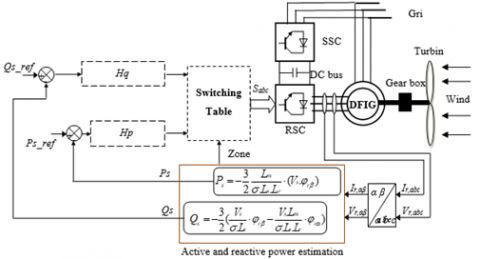
Twelve sectors DPC strategy is based on applying a switching series, which shall directly eliminate errors, which shall occur in active/reactive power, through the reference given as value and the calculated active/reactive power, to the power switching elements in the inverter [15, 16]. The twelve sectors DPC method, which is designed to regulate the reactive/active power of the DFIG-based WECS, is shown in Figure 1 [17].
This may be realized by using the generator model on the fixed d-q axis set. Reactive power, active power, and rotor flux sector zone may be calculated with the help of currents and voltages measured in the generator rotor [18].
Stator active/reactive power is estimated using (1) and (2) [19].
${{P}_{s}}=-\frac{3}{2}\frac{Lm}{\sigma .Ls.Lr}\cdot (Vs.{{\psi }_{r\beta }})$ (1)
${{Q}_{s}}=-\frac{3}{2}(\frac{Vs}{\sigma .Ls}\cdot {{\psi }_{r\beta }}-\frac{Vs.Lm}{\sigma .Ls.Lr}\cdot {{\psi }_{r\alpha }})$ (2)
Figure 1. Twelve sectors DPC method
The active and reactive powers can be reformulated by inducing angle λ between the stator and rotor vectors as follows:
${{P}_{s}}=-\frac{3}{2}\frac{Lm}{\sigma .Ls.Lr}\mathop{w}_{s}\left| \mathop{\psi }_{s} \right|\left| \mathop{\psi }_{r} \right|\sin (\lambda )$ (3)
${{Q}_{s}}=-\frac{3}{2}\frac{ws}{\sigma .Ls}\left| \mathop{\psi }_{s} \right|(\frac{M}{\mathop{L}_{r}}\left| \mathop{\psi }_{r} \right|\cos (\lambda )-\left| \mathop{\psi }_{s} \right|)$ (4)
And:
$\mathop{\Psi }_{s\alpha }=\sigma \mathop{L}_{r}\mathop{I}_{r\alpha }+\frac{M}{\mathop{L}_{s}}\mathop{\Psi }_{s}$ (5)
$\mathop{\Psi }_{s\beta }=\sigma \mathop{L}_{r}\mathop{I}_{r\beta }$ (6)
$\left| \overline{\mathop{\Psi }_{s}} \right|=\frac{\left| \overline{\mathop{V}_{s}} \right|}{\mathop{w}_{s}}$ (7)
where, Vs is the stator voltage.
$\sigma =1-\frac{\mathop{M}^{2}}{\mathop{L}_{r}\mathop{L}_{s}}$ (8)
The rotor flux can be estimated by:
$\left\{ \begin{matrix} \mathop{\Psi }_{r\alpha }=\int\limits_{0}^{t}{(}-\mathop{R}_{r}\mathop{I}_{r\alpha }+\mathop{V}_{r\alpha })dt \\ \mathop{\Psi }_{r\beta }=\int\limits_{0}^{t}{(}-\mathop{R}_{r}\mathop{I}_{r\beta }+\mathop{V}_{r\beta })dt \\\end{matrix} \right.$ (9)
And:
$\mathop{\psi }_{r}=\sqrt{\mathop{\Psi }_{r\alpha }^{2}+\mathop{\Psi }_{r\beta }^{2}}$ (10)
The angle of rotor flux is calculated by:
$\mathop{\theta }_{r}=arctg(\frac{\mathop{\Psi }_{r\beta }}{\mathop{\Psi }_{r\alpha }})$ (11)
In twelve sectors DPC method a 2-level HC (see Figure 2) is used for the active power (Hp) and a two-level HC (see Figure 3) for the reactive power (Hq). Finally, based on the values of constants Hq and Hp and the position of the rotor flux (12 region command), the proposed switching table is as shown in Table 1.
Figure 2. Active power hysteresis comparator
Table 1. Proposed switching table of twelve sectors DPC method
|
N |
Hq |
|||
|
1 |
0 |
|||
|
Hp |
||||
|
1 |
0 |
1 |
0 |
|
|
1 |
1 |
6 |
3 |
5 |
|
2 |
1 |
6 |
3 |
5 |
|
3 |
2 |
1 |
4 |
6 |
|
4 |
2 |
1 |
4 |
6 |
|
5 |
3 |
2 |
5 |
1 |
|
6 |
3 |
2 |
5 |
1 |
|
7 |
4 |
3 |
6 |
2 |
|
8 |
4 |
3 |
6 |
2 |
|
9 |
5 |
4 |
1 |
3 |
|
10 |
5 |
4 |
1 |
3 |
|
11 |
6 |
5 |
2 |
4 |
|
12 |
6 |
5 |
2 |
4 |
Figure 3. Reactive power hysteresis comparator
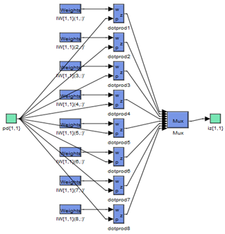
In this section, The twelve sectors DPC method with neural hysteresis comparators (DPC-NHC) is a modification of the conventional twelve sectors DPC method, where the two HCs, has been replaced by two neural controllers respectfully. This proposed method minimized the THD value of stator current, reactive/active power ripple compared to the conventional TSDPC method. The TSDPC method of the DFIG with the application of the NHC method is shown in Figure 4. This proposed method is easy to implement and simple method. However, the proposed neural controllers are the retropropagation of Levenberg-Marquardt (LM). The parameters of the LM algorithm is shown in Table 2. The structure of NHCs is illustrated in Figure 5. The block diagram of layer 1 and layer 2 is shown in Figure 6 and Figure 7 respectively.
The hidden layer of neural hysteresis comparator (NHC) is shown in Figure 8. Figure 9 shows the neural training performance of the neural networks algorithm for hysteresis comparators of reactive/active power.
Figure 4. Twelve sectors DPC-NHC method block diagram
Table 2. Parameters of the LM algorithm
|
Parameters of the LM |
Values |
|
TrainParam.Lr |
0.002 |
|
TrainParam.goal |
0 |
|
TrainParam.mu |
0.9 |
|
TrainParam.eposh |
1000 |
|
TrainParam.show |
50 |
|
Number of hidden layer |
8 |
|
Coeff of acceleration of convergence (mc) |
0.9 |
|
Functions of activation |
Tensing, Purling, gensim |
Figure 5. Block diagram of the neural hysteresis comparator
Figure 6. Layer 1
Figure 7. Layer 2
Figure 8. Hidden layer
Simulations of the proposed strategies for a DFIG are conducted by using the Matlab/Simulink software. The proposed strategies will be tested and compared in two different configurations: robustness against parameter variations and reference tracking.
4.1Reference tracking test
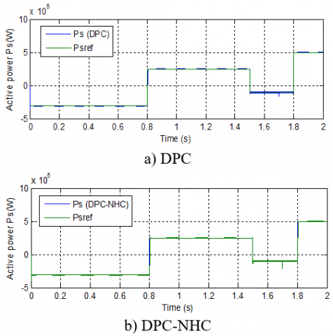
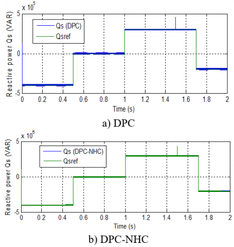
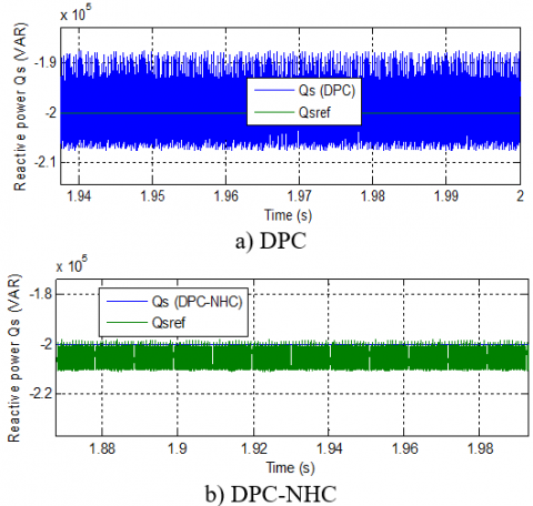
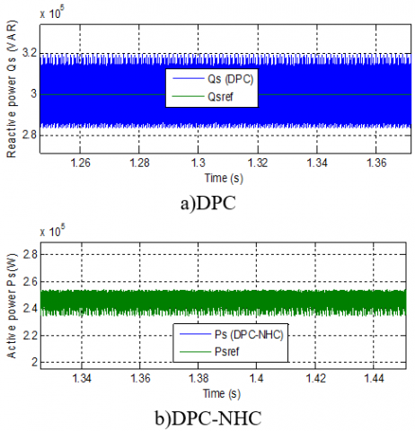
In this section, the reactive/active power tracks almost perfectly their reference values (See Figures 13-14). On the other hand, the DPC-NHC strategy reduced the reactive and active power ripples compared to the conventional DPC strategy (See Figures 15-16).
Figure 9. Neural network training performance
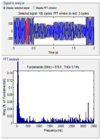
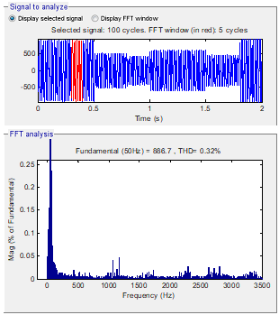
Figures 10-11 show the THD of stator current for DPC-NHC and conventional DPC method one respectively. It can be clearly observed that the THD is minimized for the DPC-NHC method (THD = 0.74 %) when compared to conventional DPC (THD = 0.32%). It is clear from the results that the DPC-NHC has satisfied performance.
Figure 10. THD (DPC)
Figure 11. THD (DPC-NHC)
Figure 12. Active power (RTT)
Figure 13. Reactive power (RTT)
Figure 14. Zoom in the active power (RTT)
Figure 15. Zoom in the reactive power (RTT)
4.2Robustness test (RT)
In this section, the parameters have been intentionally changed such as the values of the inductances Lr and Ls are divided by 2 and the resistances Rr and Rs are multiplied by 2. The DPC-NHC method reduced the active and reactive power ripples compared to the TSDPC strategy (See Figures 20-21). On the other hand, the active and stator reactive power track almost perfectly their reference values (See Figures 18-19).
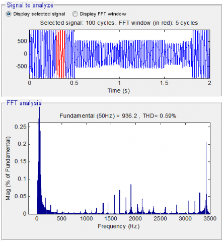
Figure 16. THD (DPC)
Figures 16-17 show the THD of the current of both techniques. It can be clearly observed that the THD is minimized for DPC-NHC strategy (THD = 0.59 %) when compared to conventional DPC (THD = 1.29%). It can be concluded that the twelve sectors DPC-NHC method is more robust than the TSDPC strategy.
Figure 17. THD (DPC-NHC)
Figure 18. Active power (RT)
Figure 19. Reactive power (RT)
Figure 20. Zoom in the active power (RT)
Figure 21. Zoom in the reactive power (RT)
In this work, the twelve sectors DPC method with neural hysteresis comparators is presented and it is compared with the conventional DPC method. The simulation results obtained for the proposed strategy illustrate a considerable reduction in active/reactive power ripple. On the other hand, the proposed DPC method reduced the THD of current compared to the traditional twelve sectors DPC method.
Table 3. DFIG parameters [20, 21]
|
Pn |
1.5 MW |
|
P |
2 |
|
Vn |
380V |
|
Rs Lr Ls Rr Lm |
0.012Ω 0.0136H 0.0137H 0.021Ω 0.0135H |
|
Fr |
0.0024Nm.s/rad |
|
J f |
1000 Kg.m2 50Hz |
[1] Benbouhenni, H., Boudjema, Z., Belaidi, A. (2018). Using three-level fuzzy space vector modulation method to improve indirect vector control strategy of a DFIG based wind energy conversion systems. International Journal of Smart Grid, 2(3): 155-171.
[2] Benbouhenni, H. (2019). Application of five-level NPC inverter in DPC-ANN of doubly fed induction generator for wind power generation systems. International Journal of Smart Grid, 3(3): 128-137.
[3] Benbouhenni, H., Boudjema, Z., Belaidi, A. (2019). Direct vector command based on three-level NSVM of a doubly fed induction generator for wind energy conversion. 2018 International Conference on Applied Smart Systems (ICASS), Medea, Algeria, pp. 1-8. https://doi.org/10.1109/ICASS.2018.8651957
[4] Benbouhenni, H., Boudjema, Z., Belaidi, A. (2018). Sensorless twelve sectors implementation of neural DPC controlled DFIG for reactive and active powers ripples reduction. Majlesi Journal of Energy Management, 7(2): 13-21.
[5] Benbouhenni, H., Boudjema, Z., Belaidi, A. (2019). Indirect vector control of a DFIG supplied by a two-level FSVM inverter for wind turbine system. Majlesi Journal of Electrical Engineering, 13(1): 45-54.
[6] Benbouhenni, H. (2019). Sliding mode with neural network regulateur for DFIG using two-level NPWM strategy. Iranian Journal of Electrical & Electronic Engineering, 15(3): 411-419. https://doi.org/10.22068/IJEEE.15.3.411
[7] Benbouhenni, H. (2018). Comparative study between PWM and SVPWM technique for a DFIG-based wind turbine system controlled by fuzzy sliding mode. Majlesi Journal of Energy Management, 7(4): 13-20.
[8] Benbouhenni, H., Boudjema, Z., Belaidi, A. (2018). Neuro-second order sliding mode control of a DFIG supplied by a two-level NSVM inverter for wind turbine system. Iranian Journal of Electrical & Electronic Engineering, 14(4): 362-373. https://doi.org/10.22068/IJEEE.14.4.362
[9] Benbouhenni, H. (2018). Neuro-sconde order sliding mode field oriented control for DFIG based wind turbine. International Journal of Smart Grid, 2(4): 209-217.
[10] Benbouhenni, H. (2018). Fuzzy second order sliding mode controller based on three-level fuzzy space vector modulation of a DFIG for wind energy conversion systems. Majlesi Journal of Mechatronic Systems, 7(3): 17-26.
[11] Benbouhenni, H. (2019). Torque ripple reduction of DTC DFIG drive using neural PI regulators. Majlesi Journal of Energy Management, 8(2): 21-26.
[12] Benbouhenni, H. (2020). ANFIS-sliding mode control of a DFIG supplied by a two-level SVPWM technique for wind energy conversion system. International Journal of Applied Power Engineering (IJAPE), 9(1): 36-47.
[13] Benbouhenni, H. (2019). Second order sliding mode with ANFIS controllers for DFIG using seven-level NSVPWM technique. Majlesi Journal of Energy Management, 8(1): 29-39.
[14] Benbouhenni, H. (2019). Direct power control of a DFIG fed by a seven-level inverter using SVM strategy. International Journal of Smart Grid, 3(2): 54-62.
[15] Shehata, E.G. (2015). Sliding mode direct power control of RSC for DFIGs driven by variable speed wind turbines. Alexandria Engineering, 54: 1067-1075. https://doi.org/10.1016/j.aej.2015.06.006
[16] Benbouhenni, H., Boudjema, Z., Belaidi, A. (2019). A direct power control of the doubly fed induction generator based on the three-level NSVPWM technique. International Journal of Smart Grid, 3(4): 216-225.
[17] Jou, S., Lee, S., Park, Y., Lee, K. (2009). Direct power control of a DFIG in wind turbines to improve dynamic responses. Journal of Power Electronics, 9(5): 781-790.
[18] Shehata, E.G., Gerges, M., Salama, M. (2013). Direct power control of DFIGs based wind energy generation systems under distorted grid voltage conditions. International Journal of Electrical Power & Energy Systems, 53: 956-966. https://doi.org/10.1016/j.ijepes.2013.06.006
[19] Benbouhenni, H. (2019). Direct power control of a DFIG fed by a seven-level inverter using SVM strategy. International Journal of Smart Grid, 3(2): 54-62.
[20] Benbouhenni, H., Boudjema, Z., Belaidi, A. (2019). A novel matlab/simulink model of DFIG drive using NSMC method with NSVM strategy. International Journal of Applied Power Engineering (IJAPE), 8(3): 221-233.
[21] Benbouhenni, H. (2019). Application of five-level NPC inverter in DPC-ANN of doubly fed induction generator for wind power generation systems. International Journal of Smart Grid, 3(3): 128-137.