Sarah Bouradi* | Rabah Araria | Karim Negadi | Fabrizio Marignetti
OPEN ACCESS
In an effort to decrease the rate at which Earth’s climate is changing and reduce the dependency on carbon based fuels. The automobile industry has shifted their focus towards a more sustainable, less harmful energy sources. The emergence of electric vehicles being a result of this shift. The aim of this work is to study the traction chain of an electric vehicle using two controlled static converters DC-DC converter and DC-AC inverter and a permanent magnet synchronous motor (PMSM) with field oriented vector control reinforced with a sliding mode control in order to improve tracking ability and robustness. The voltage source DC/AC converter is considered as a controlled power interface between the electric machine and the output of the DC storage device, the DC/DC converter is used to automatically regulate the battery operating condition in accordance to the profile of the acting on the vehicle wheels, unknown external torque. Particularly, the speed is continuously regulated by the vehicle driver via the pedal while all other regulations for absorbing or regenerating energy are internally controlled. This study is validated by simulation results which are carried out using a dynamic model of the electric vehicle. The analysis and simulations lead to the conclusion that the proposed system is feasible and can be tested on an experimental bench.
electric vehicle control, battery, fuel cell, permanent magnet synchronous motor, sliding mode control, vector control
Electric vehicles (EVs) offer the best possibilities for a healthier environment, since gasoline and diesel vehicles are among the main contributors to the emission of various gases harmful to the environment causing long-term changes to the Earth's climate and ultimately affecting the sustainability of life [1].
Taking into account the insufficiency of the battery which is considered as the power source of the electric vehicle, the use of a fuel cell (FC) as a back-up source becomes a necessity to supply the base energy in order to avoid the limited driving range. Hence for the optimum design of the motor with the selection of a proper drives.
The permanent magnet synchronous motor (PMSM) is one of the electric motors considered to drive electric vehicles for several reasons, including compact structures, high air gap density, high power density, high torque and high efficiency.
In recent years, Vector control also known as field oriented control has been applied to ac drives. Initially, vector control was used to the induction motor drive and after that, it is applied to the PMSM drive. The stator current is decoupled into torque and flux producing components allowing an independent control of both parameters as in DC motors. In view of this, the phase current is divided into two orthogonal components idand iq so that torque is proportional to the latter and flux is proportional to the former. It is undeniable that the field oriented control is a perfect method for controlling the phase currents. However, PMSM systems are nonlinear and consist of time-varying parameters with high-order complex dynamics. PI vector control method cannot meet the requirements of high performance control when the PMSM control system is subjected to external disturbance. Hence many modern control methods, such as the sliding mode controlhave been proposed to upgrade the speed control performance of PMSMs [2].
The sliding mode control is a special feature of variable structure control systems. This type of control was first studied in the Soviet Union by Emelyanov and then by other researchers such as Utkin in the 1950s. It is only from the beginning of the 1980s that the control of variable structure systems (VSS) by sliding mode became very interesting and attractive. It is considered to be one of the simplest approaches for controlling systems with an imprecise model. This is due to the good knowledge and appreciation of robustness, a very important feature characterizing this technique [3, 4].
This paper is structured as follow: the descriptions of the electric traction system along with the physical modelling of the different parts of our system with their equation model are discussed in Section 2. Section 3 is dedicated to the sliding mode control strategy applied to the EV. The simulation results of the study are shown in Section 4. Section 5 summarizes the work done in the conclusion.
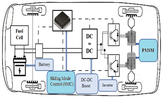
The schema illustrated in Figure 1 demonstrates the components of the electric traction system based electric vehicle. The fundamental objective of the proposed design is the control of the speed using field oriented vector control.
The constituents are made up of: a battery supplied DC voltage source, a fuel cell, a MOSFET based DC-DC boost converter, a field oriented control applied on two induction motors located in the rear of the electric vehicle connected to the two wheels. The performance results of each of the elements will be observed in order to interpret the effect of control technique [5].
Figure 1. The conversion chain of a purely electric vehicle
2.1 Fuel cell modeling
A dynamic model of the fuel cell (FC) is based on the relationship between the output voltage and potential pressure of hydrogen, oxygen and water. The overall output voltage of the fuel cell stack can be obtained as [6, 7]:
${{V}_{cell}}={{E}_{nerst}}-{{V}_{act}}-{{V}_{ohmic}}-{{V}_{con}}$ (1)
with:
Enerst: is the Nernst voltage, which is the thermodynamics voltage of the cells and depends on the temperatures and partial pressures of reactants and products inside the stack.
E0: is the standard reversible cell potential (V).
N0: is number of cells in stack.
R: is the universal gas constant (8.3145 J×mol-1×K-1).
Ts: is the stack temperature (K).
F: is the Faraday’s constant (96485 A×C×mol-1).
$\left\{ \begin{align} & {{E}_{nerst}}={{N}_{0}}\left[ {{E}_{0}}+\frac{RT}{2F}\log \left( \frac{{{P}_{{{H}_{2}}}}p_{{{O}_{2}}}^{0.5}}{{{P}_{H2O}}} \right) \right] \\ & {{V}_{ohmic}}={{R}_{m}}I \\\end{align} \right.$ (2)
where,
PH2, PO2, PH2O: are the partial pressures of hydrogen, oxygen and water (atm) respectively.
2.2 Battery modeling and control
2.2.1 Battery modeling
Different authors have proposed models for the battery, and the results of experiments on lead/acid batteries derive a model called the “CIEMAT model” representing the operation of the battery during the charging, discharging and over charging processes. Our study proposes a validated model for the battery with respect to the battery capacity for any size and type of lead-acid battery [8].
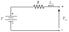
Figure 2. The battery modeling
Kirchhoff's law applied to the circuit of Figure 5 gives the equation
${{V}_{bat}}=V-R{{I}_{bat}}$ (3)
Vbat and Ibat: depend on the battery state of charge (SOC), temperature and internal resistance variations R. Throughout this study, this simple model based on the “CIEMAT model” for the battery is considered sufficiently accurate to evaluate energy management objectives and to compare the performance of multiple strategies. During the charging and discharging process, the state of charge (SOC) in terms of time (t) can be expressed by [9].
$SOC\left( t \right)=\left\{ \begin{matrix} SOC\left( t-\Delta t \right)+{{P}_{bat}}.\frac{{{\eta }_{ch}}}{{{C}_{n}}.{{V}_{dc}}}.\text{ }\!\!\Delta\!\!\text{ }t \\ SOC\left( t-\Delta t \right)+{{P}_{bat}}.\frac{1}{{{\eta }_{dis}}.{{C}_{n}}.{{V}_{dc}}}.\Delta t \\\end{matrix} \right.$ (4)
where,
∆t: is the time step,
Pbat: represents the battery power,
Cn: is the nominal capacity of the battery,
ηch and ηdis: are respectively the battery efficiencies during charging and discharging phase.
Vdc: denotes the nominal DC bus voltage. At any time step ∆t, the SOC must comply with the following constraints:
$~SO{{C}_{\min }}\le SOC\left( t \right)\le SO{{C}_{\max }}$ (5)
where,
SOCmin and SOCman are maximum and minimum allowable storage capacities, respectively.
2.2.2 Battery control
The purpose of the control system is to regulate the battery current in order to achieve the desired power [10, 11].
Figure 3. Structure of the battery control
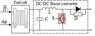
2.3 DC-DC Boost converter
The DC-DC Boost converter is the best option for power conversion in EV in order to increase the voltage level of the storage system consequently reducing the current level and the associated losses hence further improving the efficiency. The boost converter is designed based on the following formulas:
${{V}_{out}}={{V}_{bat}}\frac{D}{\left( 1-D \right)}$ (6)
where,
Vbat[V]: is the input voltage battery,
Vout[V]: is the output voltage fed motor,
D: is the duty cycle of the converter,
R[Ω]: is the resistance
f[kHz]: is the switching frequency.
The inductance L is given as:
$L=\frac{{{\left( 1-D \right)}^{2}}R}{2f}$ (7)
The Voltage ripple of the Boost converter is calculated from [12]:
$\frac{{{V}_{out}}}{{{V}_{bat}}}=\frac{D}{RCf}$ (8)
Figure 4. DC-DC Boost converter
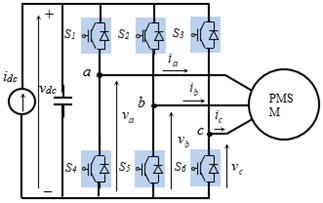
2.4 DC-AC inverter design
The EV put to use the insulated gate bipolar transistors (IGBTs) based three phase voltage source inverter (VSI) considering its efficiency and robustness along with being cheap and easy to synthesize and requires a simple control [13]. The VSI topology consists of three branches, each of which contains two mutually complementary switches in order to generate a three phase sinusoidal output supplying the PMSM motor. The VSI is connected to a DC-DC Boost converter via a large DC-link capacitor Cdc that smooths the current and voltage ripple generated by the switching action of the IGBTs.
Figure 5. DC-DC inverter design
2.5 Permanent magnet synchronous motor modeling
In the d-q rotor reference frame, PMSMs can be expressed as the following dynamic model [14, 15]:
$\left\{ \begin{align} & {{v}_{sd}}={{R}_{s}}{{i}_{sd}}+\frac{d{{\psi }_{sd}}}{dt}-{{\omega }_{r}}{{\psi }_{sq}} \\ & {{v}_{sq}}={{R}_{s}}{{i}_{sq}}+\frac{d{{\psi }_{sq}}}{dt}+{{\omega }_{r}}{{\psi }_{sd}} \\\end{align} \right.$ (9)
The stator flux linkages are given by:
$\left\{ \begin{align} & {{\psi }_{sd}}={{L}_{d}}{{i}_{sd}}+{{\psi }_{f}} \\ & {{\psi }_{sq}}={{L}_{q}}{{i}_{sq}} \\\end{align} \right.$ (10)
The electromagnetic torque and the rotor speed are given by:
$\left\{ \begin{align} & {{T}_{em}}=p{{\psi }_{f}}{{i}_{sq}}+p({{L}_{d}}-{{L}_{q}}){{i}_{sd}}{{i}_{sq}} \\ & \frac{d{{\omega }_{r}}}{dt}=\frac{p}{J}{{T}_{em}}-\frac{B}{J}{{\omega }_{r}}-\frac{p}{J}{{T}_{l}} \\\end{align} \right.$ (11)
where,
Rs: is the stator winding resistance,
Ld, Lq: are respectively the direct and quadrature inductances,
ψf: is the magnetic flux d-q,
vsd,vsq: are the direct and quadrature stator voltage,
isd,isq: are the direct and quadrature stator current,
ψsd, ψsq: are stator flux d-q components,
J: is the motor inertia,
p: is the number of pole pairs,
ωr: is the synchronous and rotor speed,
B: is the coefficient of friction.
3.1 Description of sliding mode
The design of sliding mode controllers takes stability and good performance systematically into account in its approach, which is divided into three main steps [16]:
3.1.1 Surface selection
For a given system defined by the following equation:
$\dot{x}=A(x)X+BU$ (12)
The general equation for identifying the sliding surface is of the following form:
$s(x)={{\left( \frac{\partial }{dt}+{{\lambda }_{x}} \right)}^{r-1}}e(x)$ (13)
$e(x)={{x}^{*}}-x$ (14)
where, x is the control variable, e(x) is the error, is a positive constant and r is the relative degree and $\frac{\delta}{d t} \neq 0$ to ensure controllability.
The proper choice of λx provides the elimination of the error and thus the maintaining of s(x)=0.
3.1.2 Condition of existing and convergence
The first condition of convergence takes the following form:
$s(x).\dot{s}(x)<0$ (15)
As we set the Lyapunov function:
$v(x)=\frac{1}{2}{{s}^{2}}(x)$ (16)
That the derivative will be:
$\dot{v}(x)=s(x)\cdot \dot{s}(x)$ (17)
In order to have the Lyapunov function decreasing, it is sufficient to make sure that:
$\dot{v}(x)=s(x)\cdot \dot{s}(x)<0$ (18)
3.1.3 Determination of the control law
One of the basic assumptions in the design of variable structure systems for sliding mode control is that the command must switch instantaneously from umax to umin (infinite frequency) depending on the sign of the sliding surface. In this case, very high-frequency oscillations called “chattering” occur.
$u={{u}_{eq}}+{{u}_{n}}$ (19)
ueq: is the equivalent control suggested.
un: is defined to provide the attraction of the variable to be controlled towards the surface and satisfy the convergence condition $s(x) \cdot \dot{s}(x)<0$.
${{u}_{n}}=K\cdot sign(s(x))$ (20)
where, sing(s(x))={0, s=0 and K is constant which determines the stability of the system based on reaching and settling time.
3.2 Application of sliding mode
Motor speed is an important variable in the control of electric drives, the sliding surface is chosen by [17, 18]:
$s=\omega _{r}^{*}-{{\omega }_{r}}$ (21)
where,
$\omega _{r}^{*},{{\omega }_{r}}$: are the reference and the measured rotor speed.
The derivative of Eq. (21) gives:
$\dot{s}=\dot{\omega }_{r}^{*}-{{\dot{\omega }}_{r}}$ (22)
Replacing the expression of the motor speed in Eq. (22), we will have:
$\dot{s}=\dot{\omega }_{r}^{*}-\left[ \frac{p}{J}\left( {{T}_{em}}-\frac{B}{J}{{\omega }_{r}}-{{T}_{l}} \right) \right]$ (23)
The development of Eq. (23) gives:
$\dot{s}=\dot{\omega }_{r}^{*}-\left[ \frac{3}{2J}{{p}^{2}}{{\psi }_{f}}{{i}_{q}}+\frac{B}{J}{{\omega }_{r}}+\frac{p}{J}{{T}_{l}} \right]$ (24)
It is known that in SMC’s sliding surface should reach zero to attain stability that is by substituting s(x)=0 in (24) we get:
${{i}_{q}}=\frac{2J}{3{{p}^{2}}{{\psi }_{f}}}\left( \dot{\omega }_{r}^{*}+\frac{B}{J}{{\omega }_{r}} \right)$ (25)
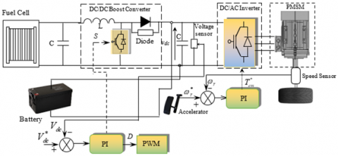
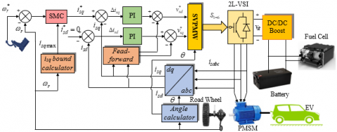
Figure 6. Overall block diagram of the proposed control system
The output current of the sliding-mode controller can be obtained as:
$i_{q}^{*}=\frac{2J}{3{{p}^{2}}{{\psi }_{f}}}\left( \dot{\omega }_{r}^{*}+\frac{B}{J}{{\omega }_{r}} \right)+Ksign(s)$ (26)
where,
$sign(s)=\left\{ \begin{matrix} 1 & s>0 \\ 0 & s=0 \\ -1 & s<0 \\\end{matrix} \right.$ (27)
The isq current will be limited to values which correspond to the optimal functioning of the vehicle. Figure 6 shows the proposed sliding mode control scheme based vector control using PMSM.
In order to evaluate the effectiveness and the dynamic performance of the proposed strategy, numerical simulations have been carried out using Matlab/Simulink software under variable load conditions on an EV powered by a 57kW PMSM, the motor parameters of which are listed in the appendix Table 1. The battery and fuel cell parameters are show in Table 2.
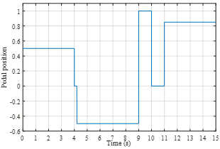
Figure 7. The acceleration pedal positions
Initially, Figure 7 shows the acceleration pedal positions to control the permanent magnet synchronous motor until it reaches its equilibrium state.
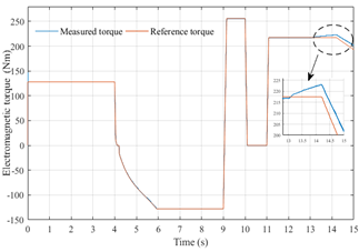
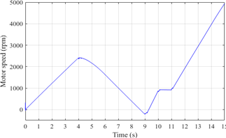
Figure 8 shows the electromagnetic torque response and their variation corresponds to the variation of the reference torque at different times. Figure 9 shows the induction motor’s speed controlled by SMC. Different speed levels are applied by changing the acceleration pedal positions.
Figure 8. Electromagnetic torque response of the EV
Figure 9. Speed response of the EV
Figure 10 illustrates the stator current components in d-q cordinates, it confirms that the current iq is the image of the electromagnetic torque Tem which validate the decoupling of the torque and the flux.
Figure 10. Stator current in d-q cordinates
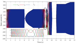
Figure 11. Stator current of the PMSM
Figure 12. Fuel cell voltage
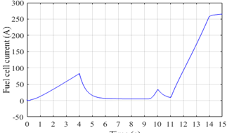
Figure 13. Fuel cell current
Figure 14. DC Bus voltage
Figures 11, 12, 13 and 14 show the stator current, the fuel cell voltage, current and the DC bus voltage respectively, oscillations appear in all of them at each period corresponding to changes in vehicle’s speed.
The results of the electric dynamics vehicle during starting and with change the acceleration pedal position and a varied road profile demonstrate that SMC reduces current ripple and guarantee the reference traction even for fast changing dynamics which shows a good agreement between experimental result and the theoretical characteristics.
This paper presents a detailed model of an EV, along with the control strategy designed to control the PMSM drive by reinforcing the Field oriented vector control with the sliding mode control in the interest of improving the performances of the system. Simulations have been carried out using Matlab/Simulink. The responses of the motor speed and the electromagnetic torque using the SMC have been evaluated and discussed. The results reveal the efficiency of the Control strategy. Where the speed significantly follows its reference also the electromagnetic torque performance is impressive even for fast changing in the reference speed in a way to imitate the driving experience of the EV on an actual road. The proposed model is simple and can be implemented easily with DSP or Dspace platform.
|
R |
universal gaz constant |
|
E0 |
standard reversible cell potential |
|
Enerst |
the Nerst voltage |
|
N0 |
number of cell in stack |
|
Ts |
the stack temperature |
|
F |
the Faraday constant |
|
${{P}_{{{H}_{2}}}}$ |
partial pressures of hydrogen |
|
${{P}_{{{O}_{2}}}}$ |
partial pressures of hyoxygen |
|
${{P}_{{{H}_{2}}O}}$ |
partial pressures of water |
|
vsd, vsq |
the d, q components of the stator voltage |
|
isd, isq |
the d, q components of the stator current |
|
ψsd, ψsq |
the d, q components of the stator flux |
|
ψf |
the magnetic flux |
|
Rs |
the stator resistance |
|
Ld, Lq |
the stator d-axis and q-axis inductance |
|
Tem |
the electromagnetic torque [Nm] |
|
Tl |
the load torque[Nm] |
|
J |
the motor inertia |
|
B |
the coefficient of friction |
|
Vbat |
voltage battery |
|
Ibat |
current battery |
|
Pbat |
power battery |
|
vdc |
DC bus voltage [V] |
|
$v_{dc}^{*}$ |
reference DC bus voltage [V] |
|
idc |
DC bus current [A] |
|
C |
DC link capacitor [mf] |
|
Cn |
nominal capacity |
|
p |
number of pole pairs |
|
f |
switching frequency |
|
s |
sliding surface |
|
D |
duty cycle of the converter |
|
ηch |
battery efficiencie during charge phase |
|
ηdisch |
battery efficiencie during discharge phase |
|
θ |
Angle position |
|
AC |
Alternatif Current |
|
DC |
Direct Current |
|
DSP |
Digital Signal Processor |
|
EV |
Electric Vehicle |
|
FC |
Fuel Cell |
|
MOSFET |
Metal Oxide Semiconductor Field Effect Transistor |
|
IGBT |
Insulated Gate Bipolar Transistor |
|
PI |
Proportionnal Intergal |
|
PMSM |
Permanent Magnet Synchonous Motor |
|
SMC |
Sliding Mode Control |
|
SVPWM |
Space Vector Pulse Width Modulation |
|
SOC |
State of Charge |
|
VSI |
Voltage Source Inverter |
|
VSS |
Variable Structure Systems |
Table 1. PMSM parameters
|
Components |
Rating values |
|
Rated power |
57 kW |
|
Stator resistance |
Rs=0.0083Ω |
|
Grid frequency |
f=50 Hz |
|
Inductance |
Ld=1,741*10-4 H, Lq=2,92 *10-4 H |
|
Flux induced by magnets |
ψf =0.0711151 Wb |
|
Number of pole pairs |
p=4 |
Table 2. Battery and fuel cell parameters
|
Components |
Rating values |
|
Battery parameters |
|
|
Nominal Voltage |
Vbat=288 V |
|
Capacity |
Cn =678.260 Ah |
|
Internal resistance |
R=0.00384 Ω |
|
Fuel Cell parameters |
|
|
Fuel cell resistance |
Rm=0.017572 Ω |
|
Nerst voltage of one cell |
${{E}_{nerst}}$=1.1729 V |
|
Stack power nominal |
P=85.5 kW |
|
Stack power maximal |
P=100 kW |
[1] Alloui, H., Achour, Y., Marouani, K., Becherif, M. (2015). Energy management based on frequency decoupling: Experimental results with fuel cell-electric vehicle emulator. IEEE 81st Vehicular Technology Conference (VTC Spring), Glasgow, pp. 1-5.
[2] Zaihidee, M., Mekhilef, F., Mubin, S., Robust, M. (2019). Speed control of PMSM using sliding mode control (SMC)—a review. Energies.
[3] Araria, R., Negadi, K., Marignetti, F. (2019). Design and analysis of the speed and torque control of IM with DTC based ANN strategy for electric vehicle application. Tecnica Italiana-Italian Journal of Engineering Science, 63(2-4): 181-188. https://doi.org/10.18280/ti-ijes.632-410
[4] Su, D.D., Dong, Y.G., Zhang, C.N. (2017). Sliding mode controller for permanent magnetic synchronous motors. Energy Procedia, 105: 2641-2646. https://doi.org/10.1016/j.egypro.2017.03.765
[5] Camara, M., Fodorien, D., Gualous, H., Bouquain, D., Miroui, A. (2008). Hybrid sources control for electric drives traction applications. 19th IEEE Int Symposium on Power Electronics, Electrical Drives, Automation and Motion, pp. 1-13. https://doi.org/10.1109/SPEEDHAM.2008.4581331
[6] Elbaset, A. (2011). Design, Modeling and Control Strategy of PV/FC Hybrid Power System. Journal of Electrical System, 7(2): 270-286.
[7] Thounthong, P., Luksanasakul, A., Koseeyaporn, P. (2013). Intelligent model-based control of a standalone photovoltaic / fuel cell power plant with supercapacitor energy storage. IEEE Transactions on Sustainable Energy, 4(1): 240-249. https://doi.org/10.1109/TSTE.2012.2214794
[8] Han, J., Charpentier, J.F., Tang, T. (2014). An energy management system of a fuel cell/battery hybrid boat. Energies, 7(5): 2799-2820. https://doi.org/10.3390/en7052799
[9] Garcia, P., Torreglosa, J. P., Fernandez, L.M., Jurado, F. (2014). Improving long-term operation of power sources in off-grid hybrid systems based on renewable energy, hydrogen and battery. Journal of Power Sources, 265: 149-159. https://doi.org/10.1016/j.jpowsour.2014.04.118
[10] Juan, P., Torreglosa, A., Garcia-Trivino, P., Fernandez Ramirez, L.M., Jurado, F. (2016). Control based on techno-economic optimization of renewable hybrid energy system for stand-alone applications. Expert Systems with Applications, 51: 59-75. http://dx.doi.org/10.1016/j.eswa.2015.12.038
[11] Amir, A., El Khateb, A., Rahim, N.A. (2016). Transformerless high gain boost and buck-boost DC-DC converters based on extendable switched capacitor (SC) cell for stand-alone photovoltaic system. Solar Energy, 171: 212-222. https://doi.org/10.1016/j.solener.2018.06.078
[12] Liu, H., Zheng, Z.D., Li, Y.D., Yao, R.D., Xu, Z. (2018). Urban rail transit power system integrated with electric vehicles based on CLLC resonant and buck-boost converter. 2018 IEEE International Conference on Electrical Systems for Aircraft, Railway, Ship Propulsion and Road Vehicles & International Transportation Electrification Conference (ESARS-ITEC), Nottingham, UK, pp. 1-7. https://doi.org/10.1109/ESARS-ITEC.2018.8607797
[13] Araria, R., Berkani, A., Negadi, K., Marignetti, F., Boudiaf, M. (2020). Performance analysis of DC-DC converter and DTC based fuzzy logic control for power management in electric vehicle application. Journal Européen des Systèmes Automatisés, 53(1): 1-9. https://doi.org/10.18280/jesa.530101
[14] Ashok Kumar, R., Balaji, K. (2017). PI and sliding mode speed control of permanent magnet synchronous motor fed from three phase four switch VSI. Journal of Mechanical Engineering Research and Developments, 40(4): 716-725.
[15] Bakhti, I., Chaouch, S., Makouf, A., Douadi, T. (2017). Speed control of permanent magnet synchronous motor using different strategy of sliding mode approach. Journal of Engineering Science and Technology, 12(10): 2778-2791.
[16] Qian, J., Chuankun, J., Pan, N., Wu, J. (2018). Improved sliding mode control for permanent magnet synchronous motor speed regulation system. Applied. Sciences, 8(12): 2491. https://doi.org/10.3390/app8122491
[17] Reimers, J., Dorn-Gomba, L., Mak, C., Emadi, A. (2019). Automotive traction inverters: Current status and future trends. IEEE Transactions on Vehicular Technology, 68(4): 3337-3350. https://doi.org/10.1109/TVT.2019.2897899
[18] Li, S., Zhou, M., Yu, X. (2013). Design and implementation of terminal sliding mode control method for PMSM speed regulation system. IEEE Transactions on Industrial Informatics, 9(4): 1879-1891. https://doi.org/10.1109/TII.2012.2226896