OPEN ACCESS
Plate heat exchangers are widespread in several fields due to their capability to transfer noticeable thermal powers despite the reduced encumbrance.
The main feature concerns the presence of parallel plates where the fluids circulate in alternate manner in counter-current configuration. These devices are highly flexible allowing for the addition or the removal of a certain number of plates in order to vary the exchange surface. The latter often is equipped with corrugation in order to improve the thermal power transfer, however pressure drops can increase significantly.
In this paper, a second law analysis was carried out in order to identify an optimal configuration of the heat exchanger that minimizes the entropy generation. The latter is determined by calculating the irreversibilities due to the heat transfer and the pressure drops. Usually, the first can be reduced with the exchange surface growth, but simultaneously the entropy generation due to the pressure drops increases. Therefore, these irreversibilities produce opposed effects and consequently an optimal configuration, that minimizes the total entropy generation, can be found. By means of a parametric study, a quality dimensionless index defined in function of the generated entropies allows for the identification of the optimal features of these heat exchangers.
design optimization, entropy generation minimization, plate heat exchanger
From several years, the entropy generation allows for the measurement of dissipated energy and of the degradation of the systems performance, therefore the approach based on its minimization was widely employed in order to attain the design optimization of several devices [1]. During the energy transformation processes, in fact, a certain rate is always unavailable and the remaining part decreases in every successive conversion, consequently the energy “quality” reduces [2]. The aim of the approach based on the entropy generation minimization is to limit as more as possible the energy degeneration. The calculation of thermodynamic efficiency requires the knowledge of the energy that can be actually available, in accordance with the exergy concept; alternatively, the quantification of the generated irreversibility could be used. The latter is determined in function of the generated entropy, whose concept was introduced by Carathéodory as a simple Pfaffian differential in relation to the multiplication factor T-1 [3], by validating the law of entropy growth for real processes by means of the well-known inequality dS>0 [4]. However, the entropy concepts assume a wider significance to extend beyond physical processes, until to evolve in extra-physical systems [5-7]. Because the entropy involves the order and disorder concepts, this parameter was employed, for instance, to optimize urban planning process [8], as well as the development of the Smart cities models [9].
A practical case involving a physical process of great interest in thermodynamic science is represented by the thermal power transferred in heat exchangers [10]. The optimization of these devices can be achieved both with thermodynamic and economical criteria, however the entropy generation minimization can be alternatively considered in order to minimize the irreversibilities associated with the heat transfer and pressure drops. Indeed, a parametric study carried out by varying several parameters determines different entropy generations, whose minimal value identify the optimal configuration. This approach was widely employed in the scientific literature, involving different types of heat exchangers and different operation modality (co or counter current, shell and tubes, etc.) [11-14].
In this paper, plate heat exchangers (PHE) have been considered because largely employed in different fields due to their capability to transfer conspicuous thermal powers despite their compact size. PHEs use parallel corrugated plates as exchange surfaces, where the fluids flow rates circulate in alternate manner in counter-current configuration (Figure 1). PHEs are flexible devices allowing for an easy modification of the exchange surface because they can be dissembled to remove or to add of a certain number of plates. The employment of corrugated surfaces facilitates the achievement of turbulent flows and consequently improves the thermal exchange, however determines noticeable pressure drops that increase with the reduction of the plates distance. The latter can be modified easily by exploiting the deformable gaskets between the plates, constrained by an upper and a lower guide bar, which can be compressed allowing for a plates pitch regulation by acting on apposite tie bolts. The number of plates, as well as their distance, the size, the type of “chevron” angle that characterizes the corrugation, the employed materials as well as the operative conditions, represent the main parameters investigated for the device optimization.
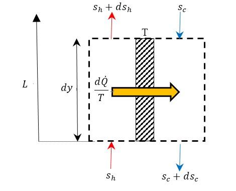
The calculation of the irreversibilities connected to the thermal transfer and the pressure drops in a counter-current PHE are based on the mass and the energy conservation laws. In order to simplify the calculation, steady-state flows, negligible thermal losses between the heat exchanger and the surrounding and constant fluids thermal properties, the latter evaluated at a fluid mean temperature, were assumed. Regarding the infinitesimal portion of heat exchanger shown in Figure 2, the irreversibility connected with the sole heat transfer process between the hot (h) and the cold (c) flow rates separated by a corrugated plate with constant temperature T, can be written as:
$d\dot{S}(T)={{\dot{m}}_{c}}d{{s}_{c}}-\frac{d\dot{Q}}{T}+{{\dot{m}}_{h}}d{{s}_{h}}+\frac{d\dot{Q}}{T}={{\dot{m}}_{c}}d{{s}_{c}}+{{\dot{m}}_{h}}d{{s}_{h}}$ (1)
from which the well-known relation for heat exchangers:
$\dot{S}(T)={{\dot{m}}_{c}}\cdot {{c}_{p,c}}\cdot \ln \frac{{{T}_{c}},out}{{{T}_{c,in}}}+{{\dot{m}}_{h}}\cdot {{c}_{p,h}}\cdot \ln \frac{{{T}_{h,out}}}{{{T}_{h,in}}}$ (2)
The irreversibilities due to the pressure drops for the two fluids with density r circulating with a velocity v along the path length L, can be written as:
$\begin{align} & \dot{S}(p)=\frac{{{{\dot{m}}}_{h}}\cdot {{f}_{h}}\cdot L\cdot v_{h}^{2}}{2\cdot {{D}_{eq,h}}}\cdot \left( \frac{1}{L}\cdot \int_{0}^{L}{\frac{dy}{{{T}_{h}}}} \right)+\frac{{{{\dot{m}}}_{c}}\cdot {{f}_{c}}\cdot L\cdot v_{c}^{2}}{2\cdot {{D}_{eq,c}}}\cdot \left( \frac{1}{L}\cdot \int_{0}^{L}{\frac{dy}{{{T}_{C}}}} \right) \\ & ==\frac{{{{\dot{m}}}_{h}}\cdot \Delta {{p}_{h}}\cdot {{F}_{h}}(NTU,\tau ,\omega )}{{{\rho }_{h}}\cdot {{T}_{h,in}}}+\frac{{{{\dot{m}}}_{c}}\cdot \Delta {{p}_{c}}\cdot {{F}_{c}}(NTU,\tau ,\omega )}{{{\rho }_{c}}\cdot {{T}_{h,in}}} \\ \end{align}$ (3)
Figure 1. Example of a disassembled PHE with 3 passes for each fluid flow rate
Figure 2. Entropic balance for a PHE configuration in counter-current operating
where Dp quantifies the pressure drops affecting the hot and the cold flow rates in the correspondent paths, whereas F is a function that takes into account the solution of the integral inside the round brackets of Eq. (3). It represents the mean value along L of the inverse of the absolute fluid temperature, and it depends on the following dimensionless parameters:
$NTU=\frac{{{H}_{e}}\cdot A}{{{{\dot{m}}}_{c}}\cdot {{c}_{p,c}}}$
(He global heat transfer coefficient, A total exchange surface);
$\tau =\frac{{{T}_{c,in}}}{{{T}_{h,in}}}$;
$\omega =\frac{{{{\dot{m}}}_{c}}\cdot {{c}_{p,c}}}{{{{\dot{m}}}_{h}}\cdot {{c}_{p,h}}}$.
In particular, for an unbalanced exchanger (w≠1):
${{F}_{h}}=\frac{\left\{ 1-\omega \cdot {{e}^{\left[ NTU\cdot (\omega -1) \right]}} \right\}\cdot \left[ \ln \left( {{\sigma }_{h}} \right)+NTU\cdot \left( \omega -1 \right) \right]}{NTU\cdot \left( \omega -1 \right)\cdot \left[ 1-\tau \cdot \omega \cdot {{e}^{\left[ NTU\cdot \left( \omega -1 \right) \right]}} \right]}$ (4)
${{F}_{c}}=\frac{\left\{ 1-\omega \cdot {{e}^{\left[ NTU\cdot (\omega -1) \right]}} \right\}\cdot \left[ \ln \left( {{\sigma }_{c}} \right)+NTU\cdot \left( \omega -1 \right) \right]}{NTU\cdot \left( \omega -1 \right)\cdot \left[ 1-\tau \cdot \omega \cdot {{e}^{\left[ NTU\cdot \left( \omega -1 \right) \right]}} \right]}$ (5)
with:
${{\sigma }_{h}}=\frac{1-\omega +\omega \cdot \tau \cdot \left\{ 1-{{e}^{\left[ NTU\cdot (\omega -1) \right]}} \right\}}{1-\omega \cdot {{e}^{\left[ NTU\cdot \left( \omega -1 \right) \right]}}}$ (6)
${{\sigma }_{c}}=\frac{\tau \cdot \left\{ 1-\omega \cdot {{e}^{\left[ NTU\cdot (\omega -1) \right]}} \right\}}{1-{{e}^{\left[ NTU\cdot \left( \omega -1 \right) \right]}}-\tau \cdot \left( \omega -1 \right)\cdot {{e}^{\left[ NTU\cdot \left( \omega -1 \right) \right]}}}$ (7)
With reference to the geometrical parameters of Figure 3, the pressure drops for each fluid can be determined by the formula suggested by [15]:
$\Delta p=\Delta {{p}_{c}}+\Delta {{p}_{p}}=4\cdot f\cdot \left( \frac{{{L}_{e}}f{{f}^{\cdot N}}}{{{D}_{eq}}} \right)\cdot \left( \frac{G_{c}^{2}}{2\cdot \rho av} \right)\cdot {{\left( \frac{{{\mu }_{av}}}{{{\mu }_{w}}} \right)}^{-0.17}}++1,4\cdot N\cdot \left( \frac{G_{p}^{2}}{2\cdot {{\rho }_{av}}} \right)=\left[ Pa \right]$ (8)
where the hydraulic diameter Deq can be set equal to 2 times the pitch b between the plates [16], Gc is the fluid flow rate normalized on the channel section area (b∙w), Gp the fluid flow rate normalized to the port area (0.25∙p∙Dp²) and N the number of passes.
Figure 3. Main geometrical parameters concerning a PHE
The friction factor f for corrugated plates can be calculated in function of the “chevron” angle b with the following correlation [16]:
$f={{\left( \frac{\beta }{30} \right)}^{0.83}}\cdot {{\left[ {{\left( \frac{30.2}{\operatorname{Re}} \right)}^{5}}+{{\left( \frac{6.28}{\sqrt{\operatorname{Re}}} \right)}^{5}} \right]}^{0.2}}$ (9)
where the Reynolds number is calculated in function of the hydraulic diameter and the fluid velocity, by calculating its density and viscosity in function of the average temperature determined along the PHE length L. These temperatures can be determined with the following relation for the hot and the cold flow rate respectively (in counter-current configuration):
${{\overline{T}}_{h}}=\frac{\left[ \left( \frac{\omega }{\omega -1} \right)\cdot \left( {{T}_{h,in}}-{{T}_{c,out}} \right)\cdot \left( 1-{{e}^{\frac{{{H}_{e}}\cdot A\cdot (1-\omega )}{\omega \cdot {{{\dot{m}}}_{h}}\cdot {{c}_{p,h}}}}} \right)+\frac{{{H}_{e}}\cdot A\cdot \left( \omega \cdot {{T}_{c,out}}-{{T}_{h,in}} \right)}{\omega \cdot {{{\dot{m}}}_{h}}\cdot {{c}_{p,h}}} \right]}{\frac{\left( \omega -1 \right)\cdot {{H}_{e}}\cdot A}{\omega \cdot {{{\dot{m}}}_{h}}\cdot {{c}_{p,h}}}}$ (10)
${{\overline{T}}_{c}}=\frac{\left[ \left( \frac{\omega }{\omega -1} \right)\cdot \left( {{T}_{h,in}}-{{T}_{c,out}} \right)\cdot \left( 1-{{e}^{\frac{{{H}_{e}}\cdot A\cdot (1-\omega )}{\omega \cdot {{{\dot{m}}}_{h}}\cdot {{c}_{p,h}}}}} \right)+\frac{{{H}_{e}}\cdot A\cdot \left( \omega \cdot {{T}_{c,out}}-{{T}_{h,in}} \right)}{\omega \cdot {{{\dot{m}}}_{h}}\cdot {{c}_{p,h}}} \right]}{\frac{\left( \omega -1 \right)\cdot {{H}_{e}}\cdot A}{\omega \cdot {{{\dot{m}}}_{h}}\cdot {{c}_{p,h}}}}$ (11)
Furthermore, the arithmetic media of the values provided by Eq. (10) and (11) is assumed as the average wall temperature (isothermal plate) required for the calculation of the viscosity mW appearing in Eq. (8). The global heat transfer coefficient is determined in function of the convective heat transfer coefficients of the involved fluids, determined with the thermo-physical properties at the fluid average temperature, and the plate characteristics. Indeed, it can be evaluated as:
${{H}_{e}}={{\left( \frac{1}{{{\overline{h}}_{h}}}+\frac{1}{{{\overline{h}}_{c}}}+\frac{t}{\lambda w} \right)}^{-1}}$ (12)
where $\overline{h}$ is the mean convective heat transfer coefficient determined both for the cold and the hot fluid, t is the plate thickness and lW its thermal conductivity. The firsts have been calculated with the following correlation suggested by [17], for turbulent flows (due to the presence of the corrugations):
$Nu=\frac{\overline{h}\cdot {{D}_{eq}}}{{{\lambda }_{av}}}=C\left( \beta \right)\cdot {{\operatorname{Re}}^{n\left( \beta \right)}}\cdot {{\Pr }^{\frac{1}{3}}}\cdot {{\left( \frac{{{\mu }_{av}}}{{{\mu }_{W}}} \right)}^{0.14}}$ (13)
where:
$C\left( \beta \right)=0.2668-6.967\cdot {{10}^{-4}}\cdot \beta +7.244\cdot {{10}^{-5}}\cdot {{\beta }^{2}}$ (14)
$n\left( \beta \right)=0.728+0.0543\cdot \sin \left[ 3.7+\frac{2\cdot \pi \cdot \beta }{90} \right]$ (15)
Finally, the generated entropies connected both the thermal transfer and the pressure drops have been made dimensionless by the multiplicative factor ${{T}_{c,in}}/\dot{Q}$.
By combining the employed parameters, the dimensionless generated entropies can be calculated in compact manner by the following relations in function of the heat exchanger efficiency e:
$EG\left( \Delta T \right)=\frac{\dot{S}\left( \Delta T \right)}{{\dot{Q}}}\cdot {{T}_{c,in}}=\left( \frac{1}{\varepsilon \cdot \left( \frac{1}{\tau }-1 \right)} \right)\cdot \left\{ \ln \left[ 1+\varepsilon \cdot \left( \frac{1}{\tau }-1 \right) \right]++\frac{1}{\omega }\cdot \ln \left[ 1-\omega \cdot \varepsilon \cdot \left( 1-\tau \right) \right] \right\}$ (16)
$EG\left( \Delta p \right)=\frac{\dot{S}\left( \Delta p \right)}{{\dot{Q}}}\cdot {{T}_{c,in}}=\left( \frac{\Delta {{p}_{h}}\cdot \tau }{{{\rho }_{h}}\cdot {{c}_{p,h}}\cdot \varepsilon \cdot \omega \cdot \left( 1-\tau \right)\cdot {{T}_{h,in}}} \right)\cdot \left[ {{F}_{h}}+\frac{\omega \cdot \Delta {{p}_{c}}\cdot {{\rho }_{h}}\cdot {{c}_{p,h}}}{\Delta {{p}_{h}}\cdot {{\rho }_{c}}\cdot {{c}_{p,c}}}\cdot {{F}_{c}} \right]$ (17)
In order to determine the best PHE configuration, the following dimensionless quality index has to assume the greatest value:
$\eta \left( S \right)=1-EG\left( \Delta T \right)-EG\left( \Delta p \right)$ (18)
In the ideal case, a unitary value is attained due to the lacking of irreversibilities, conversely it tends to decrease whit the entropy generation growths.
A commercial PHE actually available on the market for the production of domestic hot water was considered for the preliminary analysis. This device is constituted by corrugated plates in stainless steel (lW= 27 W∙m-1∙K-1) with a width w=20 cm and a height Leff =38 cm, for an effective exchange surface equal to 0.042 m² each. The corrugation V type is characterized by a chevron angle b=60° on the plate surfaces that have a mean thickness t of 1 mm. The connection with the hydraulic circuits occurs by four ports with diameter Dp of 1.25 inches to carry water mass flow rates set to 0.161 kg/s for the hot fluid entering at 70 °C, and to 0.138 kg/s for the cold one whose inlet temperature is assumed equal and constant to 15 °C. This situation represents a typical case of domestic hot water production starting from the hot fluid produced by a boiler. Assuming initially a constant water specific heat
(4186 J∙kg-1∙K-1)and the declared heat transfer coefficient provided by the manufacturer, for a precise number of plates (and consequently of passes) these data allow for the calculation of initial values of NTU and w, consequently of the PHE efficiency e and of the transferred heat power $\dot{Q}$. Successively the outlet temperatures lead to the calculation of mean fluid temperatures inside the path (${{\overline{T}}_{h}}$and ${{\overline{T}}_{c}}$), of the correspondent thermal properties until the estimation of new convective heat transfer coefficients and of the updated He value. This approach is repeated iteratively until the convergence criteria was attained. Often, four iterations stabilize the results, thus the PHE quality index h(S) was calculated for the different configurations.
In Figure 4, the trend of the entropic index is shown in function of the pitch b and of the number of plates N+1 by setting the other geometrical parameters to the mentioned values. Clearly, the lowest pitch value of 1 mm produces a maximum quality index in proximity of 13 plates (for an exchange surface of 0.409 m²), successively it decreases due to the pressure drops irreversibility growth that prevails on the reduction of the entropy generated by the heat transfer. Passing to a pitch of 1.5 mm, a maximum value can be still detected, this time for an exchange surface corresponding to 21 plates, successively asymptotical trends were detected over 27 plates for greater pitch values. The dimensionless quality index tends to increase with the number of plates and the pitch, due to the reduction of the heat transfer irreversibilities and the limitation of the pressure drops. It is interesting to note that reduced pitches lead to better quality indexes for limited exchange surfaces, whereas large pitches become preferable with the augment of the plates number. Consequently, a pitch of 1 mm offers better scores than a pitch of 3 mm when the number of plates is lower than 13, whereas better results can be achieved when the plates are greater than 27. Therefore, in order to exploit also encumbrance advantage, at parity of plates number, in presence of limited exchange surface low pitches result preferable. At parity of exchange surface, an optimal pitch value can be identified, beyond which the entropic index tends to decrease slightly despite the reduction of pressure drops due to the augment of the heat transfer entropy (Figure 5).
In particular, the effect connected to the temperature difference growth between the fluids determines an augment of the heat transfer irreversibilities that prevails on the reduction of the generated entropy due to the pressure drops.
For instance, by setting a number of plates equal to 25 (about 1 m²), the best score is determined with a pitch of 2.5 mm, whereas passing to 35 plates, (about 1.5 m²), the higher quality index is attained with a pitch of 4.5 mm.
Again, the score decreases with the pitch growth in presence of reduced exchange surfaces, whereas it increases rapidly with reduced pitches when the exchange area increases.
Figure 4. Quality indexes in function of number of plates for different pitch values
Figure 5. Quality indexes in function of the pitch for different exchange areas
Accordingly, when the exchange surface is set, the plates pitch can be regulated to attain the highest quality index.
For the considered PHE, the devices equipped with 51 plates distanced of 4.5 mm, whose quality index of 0.9875 is the highest score, represents the best configuration.
Another investigated parameter is the “chevron” angle b that was set to 30°, 45° and 60°; in particular, the effects connected with the chevron angle where studied for two values of the pitch b. In Figure 6, the trends of the quality index in function of the number of plates and for the three considered chevron angles, by setting the pitch of 4.5 mm, are shown. Clearly, the employment of wide angles produces better scores, and the latter increase with the exchange surface growth.
A more marked difference appears between 30° and the other two angles, however for large exchange surface not evident deviances between 45° and 60°, were detected. The augment of the chevron angle determines an increment of the friction factor f of Eq. (9) and consequently of the pressure drops and the correspondent irreversibilities. Furthermore, the same angle growth produces an improvement of the heat transfer coefficients for both the fluid, therefore He rise as well as the generated entropy. However, the simultaneously augment of the transferred thermal power determines a reduction of the dimensionless entropy $\dot{S}\left( T \right)$. If the pitch value is decreased to 1 mm (Figure 7), a different trend was detected: firstly, a small dependence on the chevron angle can be observed, successively the quality indexes tend to reduce with the exchange surface growth.
Figure 6. Quality indexes in function of the chevron angle with a pitch of 4.5 mm
Figure 7. Quality indexes in function of the chevron angle with a pitch of 1 mm
It is interesting to highlight that wide chevron angle are suggested in presence of limited plates number, conversely b=30° becomes the better choice for large exchange surfaces. Therefore, when pitches are limited, the effect of the pressure drops growth prevails on the improvement of the thermal exchange between the fluids. Conversely, the better heat transfer coefficients produced by wider chevron angle provide better scores in presence of a limited number of plates. Furthermore, for 18 plates distanced by 1 mm, the chevron angle does not affect the entropy generation in evident manner.
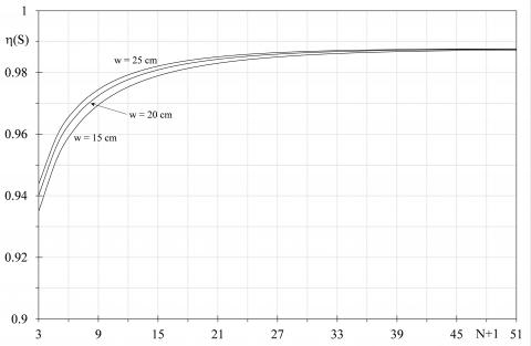
The effects on the entropy generation was investigated by changing, at parity of height, the plate width w, in order to produce a variation of exchange surface and of the passage section of both the fluid flow rates. In particular, other two widths were considered beyond the reference value: 15 cm and 25 cm. In Figure 8, the quality index trends for a PHE with a chevron angle of 60° and a pitch of 4.5 mm, is shown in function of the number of plates varying the width values.
Clearly, the exchange surface growth leads to the improvement of heat transfer and the reduction of the pressure drops, consequently the quality index tends to increase. However, for a number of plates over 30, slightly variations have been detected. By reducing the pitch to 1 mm as depicted in Figure 9, similar trends can be observed but greater deviation between the considered widths can be observed.
Figure 8. Quality indexes varying the plate width with b=60° and pitch of 4.5 mm
In particular, the largest width produces the better scores, however over a certain number of plates the dimensionless entropic indexes decrease due to the entropy generation connected to the pressure drops growth.
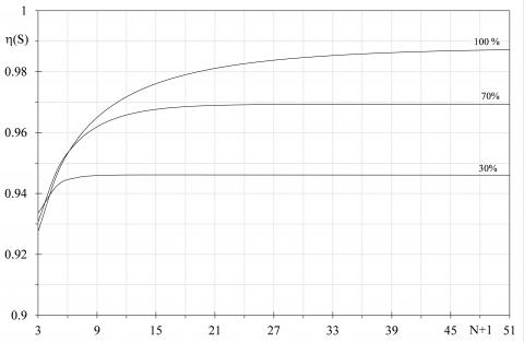
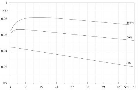
In Figure 10 the effects connected to the variation of the fluid flow rate are depicted; in particular, the cold flow rate was varied reducing it of the 30 % and the 70 % of the nominal value of 0.138 kg/s, by setting a wider pitch of 7 mm. Clearly, the reduction of the flow rate produces an evident decrement of the quality indexes due to the thermal transfer irreversibilities growth. Indeed, limited flow rates provides greater temperature difference between the inlet and the outlet, consequently the entropy generation connected to the heat transfer increases. It is interesting to highlight that slight improvement can be attained with the flow rate decrement in presence of limited exchange surfaces. Conversely, elevated flow rates produce better scores for high number of plates and an asymptotical trend is obtained beyond a precise number of plates, for every considered flow rate. Thus, for the considered pitch, 6 plates should not be overcome when the cold flow rate is 30 % of the nominal value, whereas 21 plates is the recommended number of plate with the 70 % of the nominal flow rate. Different trends were obtained by reducing the plates pitch to 1 mm, see Figure 11: this time, the lower is the flow rate, a smaller score is detected for every exchange surface. An asymptotical trend is not determined and a linear tendency was provided by setting the lowest cold flow rate value. In every case, it is confirmed the goodness to employ reduced exchange surface when the plate pitch is limited, also with a flow rate modulation.
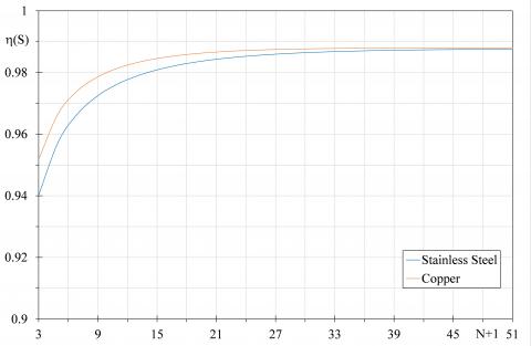
Finally, in Figure 12 the trends obtained by varying the plate material, are shown. In particular, a comparison between a stainless steel plate and a copper plate (lW=340 W∙m-1∙K-1) is reported by setting a pitch of 4.5 mm. Clearly, the advantage due to the higher thermal conductivity of the copper is evident in presence of limited exchange surfaces, whereas for an elevated number of plates the deviances between the quality indexes of the two materials are slightly different.
The entropy generation minimization method was employed in order to determine the best configuration of a Plate Heat Exchanger (PHE) by varying the main features.
Figure 9. Quality indexes varying the plate width with b=60° and pitch of 1 mm
Figure 10. Quality indexes varying the cold flow rate with b=60° and pitch of 7 mm
Figure 11. Quality indexes varying the cold flow rate with b=60° and pitch of 1 mm
Figure 12. Quality indexes with two different plate materials with b=60° and pitch of 4.5 mm
Starting from the size of a commercial PHE, a quality dimensionless index was investigated in function of the distance between the plates, their surface, the cold fluid flow rate, the plate material and the chevron angle characterizing the plate corrugations. The latter, in fact, are often employed in order to increase the exchange surface and to improve the heat transfer between the fluids.
However, the same corrugations are responsible of noticeable frictions between the fluids and the plates, therefore irreversibilities connected to pressure drops cannot be neglected. The generated entropies due to the heat transfer process and the pressure drops produce opposite effects therefore an optimal PHE configuration can be identified. These irreversibilities were made dimensionless by normalizing them with respect to the actual transferred thermal power and the inlet temperature of the cold fluid, in order to determine the quality dimensionless index as the complement of the total generated entropy. When the latter assumes the highest value, the best PHE configuration is recognized and, in the ideal case, it assumes a unitary value due to the absence of irreversibilities. The quality index trends have shown that in correspondence of limited pitches, the effects connected to the pressure drop irreversibilities prevails on the augment of the exchange surface. Conversely, these pitches allow for the attainment of better scores when the exchange surface is limited due to the improved thermal exchange that prevails on the pressure drops irreversibility. By setting the exchange surface, an optimal pitch can be identified for every PHE configuration and the score tends to decrease slightly with the pitch growth due to the greater temperature difference between the fluids that determines an increment of the heat transfer entropy, whereas pressure drops irreversibilities reduce.
In presence of high pitches, the chevron angle should be set to wider values because it improves largely the heat transfer process, despite an increment of the pressure drops. For reduces pitches a wide chevron angle produces better score only for reduced exchange surfaces, otherwise reduced angle becomes preferable. Finally, the augment of the exchange surface, at parity of the other investigated parameters, always leads to better scores, however asymptotical trends were detected for large pitches, consequently a limit value of the exchange area can be identified. Conversely, for reduced pitches an optimal exchange area can be found and it varies in function the plate width. Globally, in presence of large exchange surfaces, the employment of high pitches, as well as of wider chevron angle and plates width, is recommended. Instead, for reduced exchange areas, limited pitches produce better results, however wider chevron angles and plate widths should to be employed. Finally, the employment of more conductive and expensive plate materials, as copper, is recommended only in presence of limited exchange surfaces.
In conclusion, every PHE could be characterized by different optimal configurations in relation to the operating conditions, in particular the fluid flow rates that modify the heat transfer and the friction losses, however the proposed model is flexible allowing for the evaluation of the highest quality index that identifies the best PHE shape and size for different functioning conditions.
A exchange surface m²
b plate pitch mm
cp specific heat J∙kg-1∙K-1
C Nusselt correlation coefficient
D diameter m
EG generated entropy
F pressure drop function
f friction factor
G normalized flow rate kg∙s-1∙m-2
$\overline{h}$ mean convect. heat transf. coeff. W∙m-2∙K-1
He PHE global heat transf. coeff. W∙m-2∙K-1
L heat exchanger length m
$\dot{m}$ mass flow rate kg∙s-1
n Nusselt exponent correlation
N number of passes
NTU PHE number of transfer units
Nu Nusselt number
p Pressure Pa
Pr Prandtl number
$\dot{Q}$ thermal power W
Re Reynolds number
$\dot{S}$ entropy W∙K-1
s specific entropy J∙kg-1∙K-1
t plate thickness mm
T temperature K
v fluid velocity m∙s-1
w plate width cm
y vertical direction
Greek symbols
b chevron angle
D variation
e PHE efficiency
l thermal conductivity W∙m-1∙K-1
m dynamic viscosity Pa∙s
h quality index
r density kg∙m-3
s pressure drop coefficient
t temperature ratio
w thermal capacity ratio
Subscripts
av average
c cold
eff plate height
eq equivalent
h hot
in inlet
out outlet
p pipe port
w wall
[1] Bejan A. (1995). Entropy generation minimization: The method of thermodynamic optimization of finite-size systems and finite-time processes. first edition, CRC Press, Boca Raton (USA). https://doi.org/10.1201/9781482239171
[2] Prigogine I, Van Rysselberghe P. (1965). Introduction to thermodynamics of irreversible processes. Wiley, New York 1(4). https://doi.org/10.1149/1.2425756
[3] Caratheodory C. (1909). Mathematische annalen. N° 67, Berlin.
[4] Sychev VV. (1991). The differential equations of thermodynamics. 2nd edition, CRC Press.
[5] Nicoletti G, Arcuri N, Bruno R, Nicoletti G. (2016). On the generalized concept of entropy for physical, extra-physical and chemical processes. International Journal of Heat and Technology 33(4): 21-38. http://dx.doi.org/10.18280/ijht.34S103
[6] Martyushev LM, Seleznev VD. (2006). Maximum entropy production principle in physics, chemistry and biology. Physics Reports 426: 1-45. https://doi.org/10.1016/j.physrep.2005.12.001
[7] Longo G. (1980). Teoria dell'informazione Ed. Boringhieri, Turin (Italy).
[8] Arcidiacono G, Arcidiacono S. (2006). Entropia, sintropia, informazione. Una nuova teoria unitaria della fisica, chimica e biologia. 2nd Edition, Ed. Arcobaleno, Rome (Italy).
[9] Sguglio A, Arcuri N, Bruno R. (2018). Integration of social science in engineering research for smart cities. The Italian Case of the RES NOVAE Project. Proceeding of 2018 IEEE International Conference on Environment and Electrical Engineering, Palermo (ITALY), p. 6. https://doi.org/10.1109/EEEIC.2018.8493774
[10] Bejan A. (1997). The concept of irreversibility in heat exchanger design: counter flow heat exchangers for gas-to-gas applications. Journal of Heat Transfer 99(3). https://doi.org/10.1115/1.3450705
[11] Lerou PPPM, Veenstra TT, Burger JF, Ter Brake HJM, Rogalla H. (2005). Optimization of counterflow heat exchanger geometry through minimization of entropy generation. Cryogenic 45(10-11): 659-669. https://doi.org/10.1016/j.cryogenics.2005.08.002
[12] Johannessen E, Nummedal L, Kjelstrup S. (2002). Minimizing the entropy production in heat exchange. International Journal of Heat and Mass Transfer 45: 2649-2654. https://doi.org/10.1016/S0017-9310(01)00362-3
[13] Guo J, Cheng L, Xu M. (2009). Optimization design of shell-and-tube heat exchanger by entropy generation minimization and genetic algorithm. Applied Thermal Engineering 29: 2954-2960. https://doi.org/10.1016/j.applthermaleng.2009.03.011
[14] Ogulata RT, Doba F. (1998). Experiments and entropy generation minimization analysis of a cross-flow heat exchanger. International Journal of Heat and Mass Transfer 41: 373-381. https://doi.org/10.1016/S0017-9310(97)00129-4
[15] Neagu AA, Koncsag CI, Barbulkescu A, Botez E. (2016). Estimation of pressure drop in gasket plate heat exchangers. Ovidius University Annals of Chemistry 27: 62-72. https://doi.org/10.1515/auoc-2016-0011
[16] Muley A, Manglik RM. (1999). Experimental study of turbulent flow heat transfer and pressure drop in a plate heat exchanger with chevron plates. ASME Journal of Heat Transfer 121: 110–117. https://doi.org/10.1115/1.2825923
[17] Mulley A, Manglik RM. (2000). Enhanced thermal-hydraulic performance optimization of chevron plate heat exchangers. Int. J. Heat Exchangers 1(1): 3–18.