OPEN ACCESS
This paper investigates a dual star synchronous machine powered by two independent three-level voltage source inverters integrated in a wind turbine system (Figure 1). The dual star synchronous machine is used in areas of high power industrial applications such as naval propulsion, traction systems and renewable energy. This use is motivated by several important advantages compared to classical three-phase machine.
In this work, the machine side converters control the dq component current by a conventional method based PI regulator, and then the load side converters control the DC bus voltage using sliding mode approach and the RMS voltage load.
The validity of the proposed control technique is verified by Matlab/Simulink. Simulation results presented in this paper confirm the validity and feasibility of the proposed control approach, and can be tested on experimental setup.
dual star synchronous machine (DSSM), wind energy, three level converters, electrical drive, sliding mode control, wind energy conversion system (WECS)
Sustainable electrical energy is a major concern of modern society. Wind power represents a renewable and carbon-free energy resource, which can be made available on a large scale by wind energy conversion systems (WECSs). During the last two decades, electricity generation by wind power experienced a vast expansion leading to a global cumulative installed generation capacity [1-2].
The electrical AC machines drives have a very important role in the operation of industrial systems. The performances requested from these machines are constantly increasing from the point of view of the delivered torque waveform and dynamics speed quality [3].
The progress achieved in the domain of the power electronics permitted to construct some static converters at variable frequency. For high powers, the use of the synchronous machines associated multilevel inverters especially finds its application in the naval propulsion, electric traction and the renewable energy conversion [1-4].
The major disadvantage of the conventional power supply of the synchronous machines based converters with thyristor is that it generates a high waveform of the electromagnetic torque. To solve the problem, we proceed to an MSSD whose windings are shifted by 30 degrees by another powered by multilevel converters [5-6].
The evolution of high power electronic components has contributed to power segmentation by controlling the switching of these components. In addition, at low and medium power, two-level inverters generally provide the power supply of these machines. However, for high powers, this power supply often requires multilevel inverters [6].
We know that the machine model is non-linear and strongly coupled between the rotor flux and the electromagnetic torque, which makes its control very difficult. Several control strategies have been proposed in the literature, [7-14]. In our case, the machine side converters control the dq component current by a conventional method based PI regulator, and then the load side converters control the DC bus voltage using sliding mode approach and the RMS voltage load.
The structure of the presented work is organized as follow: The description of the proposed approach is set in section 2. The physical modeling and control of different part of our system with their equations model is set in section 3. The simulations results of the studied are presented in section 4. Section 5 summarizes the work done in the conclusion.
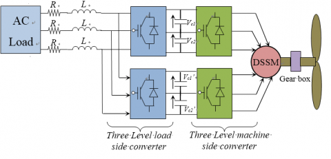
The considered wind energy conversion system is shown in Figure 1 and represents a state of the art WECS: a variable-speed, variable-pitch, three bladed, horizontal axes and lift turbine in up-wind position. Only a single wind turbine is considered, without aerodynamical interaction between multiple turbines as described by the wake effect. Regarding the type of generator (in our case Dual Star Synchronous Machine (DSSM)), the WECS might or might not comprise a gear between turbine and generator. The generator feeds the converted power through a full-scale back-to-back converter and load-side filter.
The transformer is not explicitly modeled, but could easily be added. The grid is assumed symmetrical and stiff, so that the grid-side voltage source inverter (VSI) operates in grid-feeding mode. So, an electrical interaction between multiple WECS is not considered.
Figure 1. Schematic diagram of the proposed WECS
3.1 Model of dual star synchronous machine
The studied machine is a double star synchronous machine (DSSM) with stator is made up of two three-phase windings shifted between them of an angle (30◦), and an exciting winding shifted compared to the axis of the stator phase of an angle measuring the position of the rotor [3].
$\left(\begin{array} v_{d1}\\ v_{d2}\\ v_{q1}\\ v_{q2}\\ \end{array} \right)$=$R_S\left(\begin{array} i_{d1}\\ i_{d2}\\ v_{q1}\\ i_{q2}\\ \end{array} \right)$+$\left( \begin{array}{cccc} \frac{d}{dt} & 0 & \omega & 0\\ 0 & \frac{d}{dt} & 0 & \omega\\ -\omega & 0 & \frac{d}{dt} & 0\\ 0 & -\omega & 0 & \frac{d}{dt}\\ \end{array} \right)$$\left(\begin{array} \psi_{d1}\\ \psi_{d2}\\ \psi_{q1}\\ \psi_{q2}\\ \end{array} \right)$ (1)
The rotor excitation circuit is written as
\({{v}_{f}}={{R}_{f}}{{i}_{f}}+\frac{d{{\psi }_{f}}}{dt}\) (2)
and the corresponding flux relations are given by:
\({{\psi }_{d1}}={{L}_{d}}{{i}_{d1}}+{{M}_{d}}{{i}_{d2}}+{{M}_{fd}}{{i}_{f}}\) (3)
\({{\psi }_{d2}}={{L}_{d}}{{i}_{d2}}+{{M}_{d}}{{i}_{d1}}+{{M}_{fd}}{{i}_{f}}\) (4)
\({{\psi }_{q1}}={{L}_{q}}{{i}_{q1}}+{{M}_{q}}{{i}_{q2}}\) (5)
\({{\psi }_{q2}}={{L}_{q}}{{i}_{q2}}+{{M}_{q}}{{i}_{q1}}\) (6)
\({{\psi }_{f}}={{L}_{f}}{{i}_{f}}+{{M}_{fd}}\left( {{i}_{d1}}+{{i}_{d2}} \right)\)(7)
The electromagnetic torque developed by the machine is:
\({{T}_{em}}=p({{\psi }_{d1}}{{i}_{q1}}-{{\psi }_{q1}}{{i}_{d1}}+{{\psi }_{d2}}{{i}_{q2}}-{{\psi }_{q2}}{{i}_{d2}})\) (8)
The mechanical equation is:
\(\frac{Jd\omega }{dt}=p{{T}_{em}}-{{f}_{r}}\omega -p{{T}_{l}}\) (9)
3.2 Modeling of the wind turbine
The wind energy conversion system is complex because of the multiplicity of existing fields, aerodynamic, mechanical, and electric; and factors determining the mechanical power, as wind speed, dimension, and turbine shape.
Input and output variables of the wind turbine can sum up as follows:
(1) Wind speed that determines the primary energy to the admission of turbine.
(2) Tip-Speed ratio (T.S.R) defined by the ratio of the linear speed in tip of blades of the turbine on the instantaneous wind speed, and given by the following expression [15].
\(\lambda =\frac{{{\omega }_{m}}R}{{{v}_{wind}}}\) (10)
The fundamental equation of dynamics permits to determine the mechanical speed evolution from the total mechanical torque applied to the rotor that is the sum of all torques applied on the rotor:
The mechanical power that wind turbine can extract from the wind is calculated by:
\({{P}_{m}}=\frac{1}{2}\rho \pi {{R}^{2}}{{C}_{p}}\left( \lambda ,\beta \right)v_{wind}^{3}\) (11)
3.3 Three-level inverter modeling
A three-level inverter differs from a conventional two-level inverter in that it is capable of producing three different levels of output phase voltage. The structure of a three-level neutral point clamped inverter is shown in figure 2. When switches 1 and 2 are on, the output is connected to the positive supply rail. When switches 3 and 4 are on, the output is connected to the negative supply rail. When switches 2 and 3 are on, the output is connected to the supply neutral point via one of the two clamping diodes [16-17].
Figure 2. Three-level inverter (k =1 for first inverter and k =2 for second inverter)
The functions of connection are given by:
\(\left\{ \begin{matrix} {{F}_{xk2}}={{S}_{xk1}}.{{S}_{xk2}} \\ {{F}_{xk1}}={{S}_{xk2}}.{{S}_{xk3}} \\ \end{matrix} \right.\), \(x=a,b,c\) (12)
The phase voltage $v_{ak}$, $v_{bk}$, $v_{ck}$ can be written as:
\(\left( \begin{matrix} {{v}_{ak}} \\ {{v}_{bk}} \\ {{v}_{ck}} \\ \end{matrix} \right)=\left( \begin{matrix} 2{{F}_{ak2}}-{{F}_{bk2}}-{{F}_{ck2}} \\ 2{{F}_{bk2}}-{{F}_{ak2}}-{{F}_{ck2}} \\ 2{{F}_{ck2}}-{{F}_{ak2}}-{{F}_{bk2}} \\ \end{matrix}\text{ }\begin{matrix} 2{{F}_{ak1}}-{{F}_{bk1}}-{{F}_{ck1}} \\ 2{{F}_{bk1}}-{{F}_{ak1}}-{{F}_{ck1}} \\ 2{{F}_{ck1}}-{{F}_{ak1}}-{{F}_{bk1}} \\ \end{matrix} \right)\left( \begin{matrix} {{V}_{dc}} \\ \frac{{{V}_{dc}}}{2} \\ \end{matrix} \right)\) (13)
3.4 Load side control
The dc-link voltage tracking error has the following dynamic:
\({{\dot{e}}_{V}}={{\dot{V}}_{dc}}-\dot{V}_{dc}^{*}\) (14)
\({{\dot{e}}_{V}}=\frac{2{{V}_{dci}}}{3{{V}_{eff}}}C{{i}_{load}}-\frac{1}{C}{{i}_{s}}+{{V}_{d}}-\dot{V}_{dc}^{*}\) (15)
Choice of the sliding surface
The quantity to be set is the average value $V*_{dc1}$, $V*_{dc2}$ of the two input voltages $V_{dc1}$ and $V_{dc2}$ of the two three-phase inverters. For this, we choose the sliding surface for each inverter as follows:
\({{S}_{i}}={{V}_{dcref}}-{{V}_{dc}}\) (16)
The derivative of this surface is
\({{\dot{S}}_{i}}=-{{\dot{V}}_{dc}}\) (17)
Condition of attractiveness and determination of the control:
The condition S(x)S(x)<0 ensures the attractiveness of the trajectory towards the sliding surface. To do so, simply choose:
\(S_{i}^{g}\left( x \right)=-{{k}_{1}}sign\left( {{S}_{i}} \right)-{{k}_{2}}{{S}_{i}}\) (18)
with k1 and k2 positive constants.
We then deduce the magnitude of the command, which is the effective value of the reference currents of the load:
\({{i}_{d}}=\frac{2{{V}_{dci}}}{3{{V}_{eff}}}C\left( {{i}_{load}}-{{k}_{1}}sign\left( {{S}_{i}} \right)-{{k}_{2}}{{S}_{i}} \right)\) (19)
Note that this command id consists of the equivalent command $i_{d-eq}$, which allows the convergence towards the point of equilibrium on the sliding surface, and the attractive command $i_{d-a}$ which depends on the surface and ensures the attractiveness of the trajectory towards the latter.
\({{i}_{deq}}=\frac{2{{V}_{dci}}}{3{{V}_{eff}}}C{{i}_{load}}\) (20)
and:
\({{i}_{d-a}}=\frac{2{{V}_{dci}}}{3{{V}_{eff}}}C\left( {{k}_{1}}sign\left( {{S}_{i}} \right)-{{k}_{2}}{{S}_{i}} \right)\) (21)
i=1: first stator,
i=2: second stator.
Figure 3. Sliding mode control scheme for the load side
3.5 Generator side control
The DSSM is multivariable, nonlinear and highly coupled. The principle of vector control is to bring the coupled nonlinear model of the DSSM to that of a DC machine, which has a torque and flux independently controlled in order to obtain the desired Performances. The main objective is to decouple the electromagnetic torque from the direct components of stator flux. As a result, to control the torque it is necessary to impose the components of the two stator currents $i_{d1}$, $i_{d2}$, $i_{q1}$, $i_{q2}$.
The electromagnetic torque is optimal for a decoupled control strategy with $i_{d1}=0$ and $i_{d2}=0$ [18, 20].
Based on the relations (3) to (8) and supposing that the two inverters provide equitably half of the consumption by the machine. The torque is written as:
\({{T}_{g}}=p\left( {{\psi }_{d1}}{{i}_{q1}}+{{\psi }_{d2}}{{i}_{q2}} \right)\) (22)
After this choice, we then obtain a model where the components $i_{d1}$ and $i_{d2}$ are the only commands of the pair
.\(i_{d1}^{*}=0\), \(i_{q1}^{*}=\frac{\frac{T_{g}^{*}}{2}}{p{{M}_{fd}}{{i}_{f}}}\) (23)
\(i_{d2}^{*}=0\), \(i_{q2}^{*}=\frac{\frac{T_{g}^{*}}{2}}{p{{M}_{fd}}{{i}_{f}}}\) (24)
For a fixed excitation rotor current $i_f$, the electromagnetic torque is proportional to the $i_q$ component of the stator current if however its $i_d$ component is maintained constant. Thus, it is possible to impose by the means of the $i_d$ component an operating at optimal torque and stator flux constant.
Figure 4. Block diagram the generator side control
Figure 4 illustrates the scheme of vector control-DSSM powered by two three level inverters, the decoupled control strategy of the machine is ensured by the decoupling block obtained by the model of the machine.
To verify the validity of the proposed controller, the system was simulated with Matlab SimPowerSystem using the DSSM powered with two three level inverter debits in a permanent active load and two other charges inserted in different periods. The first load is an inductive load in the period between 7 and 8 s and the second is a capacitive load introduced in the period of 15 to 20 s. For the reference speed of 75 rad/s, 104 rad/s and 55 rad/s was imposed in moments 9, 13.5 and 25 s respectively.
Figure 5 illustrates the speed of the generator which follows well their reference as well as, the electromagnetic torque which has a slight fluctuation which depends on the variation of the load in the instants [7s, 8s] and [8s, 15s].
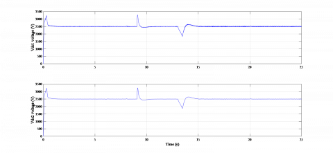
Figure 6 shows the voltage of the DC bus vc1 and vc2 of the first converter, is well kept constant at the specified value (2500V) which constitutes an important advantage and proves the effectiveness of the proposed structure.
Figure 5. Speed and torque responses of DSSM
Figure 6. DC voltage of one converter
Figure 7. The stator current of the DSSM (iabc, ixyz)
Figure 8. Active and reactive power responses of the load
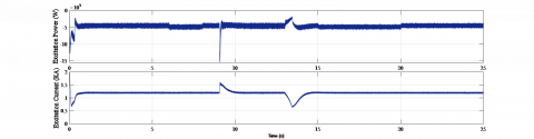
Figure 9. Current and power excitation
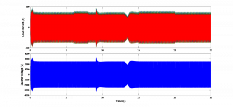
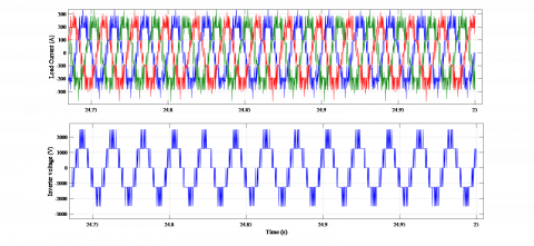
Figure 10. Load current and the output voltage of the inverter
Figure 11. Zoom of the load current and the output voltage of the inverter
The stator current $i_{abc}$ and $i_{xyz}$ of the DSSM are presented in Figure 7.
Figures 8 and 9 show the active and reactive power of the load and the power excitation respectively, we note that the current excitation remains constant despite the variation of the loads (Figure 9).
Figure 10 shows the waveform of the voltage and current load, in these Figures, we note that the RMS voltage keeps the constant values.
Figure 10 illustrate the zoomed of the current and voltage of the load respectively.
We conclude that the control of the conversion chain proves its effectiveness and the application of the three-level NPC inverter improves the quality of power in the system studied.
This paper has proposed an improved Sliding Mode Control of Wind Energy Conversion System using Dual Star Synchronous Machine and Three Level Converter. The application of the sliding mode control strategy proves its effectiveness of the control of DC bus voltage in the load side converters. This made RMS voltage load control easier with better performance.
The application of the vector control to the DSSM permitted to simplify the model of the machine and to decouple it. The performances of the machine supplied by two three-level inverters controlled via conventional PI regulator are interesting to know an appreciable dynamic behavior and a rejection of effective disturbance.
The results of the simulation clearly show the good performances obtained with the sliding mode control on the load side inverter and the vector control based PI in the machine side inverter.
The proposed approach can be validated with experimental setup easily using FPGA, DSP or Dspace platform.
[1] Boudana D, Nezli L, Çani AT, Mahmoudi MO, Tadjine M. (2012). Robust DTC based on adaptive fuzzy control of double star synchronous machine drive with fixed switching frequency. Journal of Electrical Engineering 63(3): 133-143. https://doi.org/10.2478/v10187-012-0021-y
[2] Kortas I, Sakly A, Mimouni MF. (2017). Optimal vector control to a double-star induction motor. Energy 131: 279e288. http://dx.doi.org/10.1016/j.energy.2017.03.0580360-5442
[3] Bermudeza M, Gomozova BO, Kestelyna X, Barrerob F, Nguyena NK, Semaila E. (2018). Model predictive optimal control considering current and voltage limitations: Real-time validation using OPAL-RT technologies and five-phase permanent magnet synchronous machines. International Association for Mathematics and Computers in Simulation (IMACS). https://doi.org/10.1016/j.matcom.2018.07.005
[4] Chatterjeea S, Chatterjee S. (2018). A novel speed sensor-less vector control of Dual Stator Induction machine with space vector based advanced 9-zone hybrid PWM for grid connected wind energy generation system. Electric Power Systems Research. https://doi.org/10.1016/j.epsr.2018.02.021
[5] Nezli L, Mahmoudi MO. (2010). Vector control with optimal torque of a salient-pole double star synchronous machine supplied by three–level inverters. Journal of Electrical Engineering 61(5): 257-263.
[6] Nayli A, Guizani S, Ammar FB. (2017). Modeling and analysis of a novel dual open-end stator windings wound rotor synchronous machine with dampers. Turkish Journal of Electrical Engineering and Computer Sciences 28-30. https://doi.org/ 10.1109/ICoSC.2015.7152785
[7] Benyoussef E, Meroufel A, Barkat S. (2014). Three-level direct torque control based on space vector modulation of double star synchronous machine. International Journal of Energy 8: 53-59.
[8] Andriollo M, Bettanini G, Martinelli G, Morini A, Tortella A. (2009). Analysis of double-star permanent-magnet synchronous generators by a general decoupled d–q model. IEEE Transaction on Industry Applications 45(4): 1416-1424. https://doi.org/10.1109/TIA.2009.2023553
[9] Yang B, Yu T, Shu HC, Dong J, Jiang L. (2017). Robust sliding-mode control of wind energy conversion systems for optimal power extraction via nonlinear perturbation observers. Applied Energy 210: 711-723. http://dx.doi.org/10.1016/j.apenergy.2017.08.027
[10] Eshaft SHA. (2017). Grid and rotor sides of doubly-fed induction generator-based wind energy conversion system using sliding mode control approach. A thesis submitted to Saint Mary’s University, Halifax, Nova Scotia, in partial fulfillment of the requirements for the degree of Master of Science in Applied Science.
[11] Beltran B, Ahmed-Ali, Benbouzid MEH, Member S. (2008). Sliding mode power control of variable-speed wind energy conversion systems. IEEE Transaction on Energy Conversion 23(2): 551-558. http://dx.doi.org/10.1109/TEC.2007.914163
[12] Merabet A, Ahmed KT, Ibrahim H, Beguenane R, Member, IEEE. (2016). Implementation of Sliding Mode Control System for Generator and Grid Sides Control of Wind Energy Conversion System, IEEE Transaction on Sustaible Energy 1327-1335. http://dx.doi.org/10.1109/TSTE.2016.2537646
[13] Errami Y, Ouassaid M, Cherkaoui M, Maaroufi M. (2015). Sliding mode control scheme of variable speed wind energy conversion system based on the PMSG for utility network connection. Advances and Applications in Sliding Mode Control systems, Studies in Computational Intelligence 576. http://dx.doi.org/10.1007/978-3-319-11173-5_6
[14] Belarbi S, Koussa DS, Djoudi A. (2017). Sliding mode control for PMSG-based wind power system. 4th Euro-Mediterranean Conference on Materials and Renewable Energies IOP Publishing (EMCMRE-4) Marrakech-Morocco, pp. 1-9. http://dx.doi.org/10.1088/1742-6596/1081/1/012012
[15] Chavira F, Ortega-Cisneros S, Rivera J. (2017). A novel sliding mode control scheme for a PMSG-based variable speed wind energy conversion system. Energies 2017 10: 1476. http://dx.doi.org/10.3390/en10101476
[16] Naas B, Nezli BL, Naas B, Mahmoudi MO, Elbar M. (2012). Direct torque control based three level inverter-fed double star permanent magnet synchronous machine. Energy Procedia 18: 521-530. http://dx.doi.org/10.1016/j.egypro.2012.05.063
[17] Dehghanzadeh AR, Behjat V. (2015). Dynamic modeling and experimental validation of a dual stator PMSG for low speed application. Gazi University Journal of Science 28(2): 275-283.
[18] Zribi M, Alrifai M. (2017). Mohamed Rayan, sliding mode control of a variable- speed wind energy conversion system using a squirrel cage induction generator. Energies 10(5): 604-604. http://dx.doi.org/10.3390/en10050604
[19] Khemiri N, Khedher A, Mimouni MF. (2012). Wind energy conversion system using DFIG controlled by backstepping and sliding mode strategies. International Journal of Renewable Energy Research 2(3).
[20] Hu YS, Zhu ZQ, Fellow, IEEE, Liu K. (2013). Current control for dual 3-phase PM synchronous motors accounting for current unbalance and harmonics. IEEE Journal of Emerging and Selected Topics in Power Electronics 2(2): 272-284. http://dx.doi.org/10.1109/JESTPE.2014.2299240.